EP1319875A2 - Dichtungsanordnung an zwei einander zugewandten Flächen - Google Patents
Dichtungsanordnung an zwei einander zugewandten Flächen Download PDFInfo
- Publication number
- EP1319875A2 EP1319875A2 EP02014913A EP02014913A EP1319875A2 EP 1319875 A2 EP1319875 A2 EP 1319875A2 EP 02014913 A EP02014913 A EP 02014913A EP 02014913 A EP02014913 A EP 02014913A EP 1319875 A2 EP1319875 A2 EP 1319875A2
- Authority
- EP
- European Patent Office
- Prior art keywords
- facing surfaces
- mutually facing
- sealing arrangement
- sealing
- bead
- Prior art date
- Legal status (The legal status is an assumption and is not a legal conclusion. Google has not performed a legal analysis and makes no representation as to the accuracy of the status listed.)
- Withdrawn
Links
- 238000007789 sealing Methods 0.000 title claims abstract description 36
- 239000003566 sealing material Substances 0.000 claims abstract description 11
- 239000011324 bead Substances 0.000 claims description 43
- 238000005520 cutting process Methods 0.000 claims description 13
- 238000000034 method Methods 0.000 claims description 7
- 239000000446 fuel Substances 0.000 claims description 6
- OKTJSMMVPCPJKN-UHFFFAOYSA-N Carbon Chemical compound [C] OKTJSMMVPCPJKN-UHFFFAOYSA-N 0.000 claims description 4
- 229910002804 graphite Inorganic materials 0.000 claims description 4
- 239000010439 graphite Substances 0.000 claims description 4
- 239000011230 binding agent Substances 0.000 claims description 3
- 238000007650 screen-printing Methods 0.000 claims description 3
- 229920002943 EPDM rubber Polymers 0.000 claims description 2
- YCKRFDGAMUMZLT-UHFFFAOYSA-N Fluorine atom Chemical compound [F] YCKRFDGAMUMZLT-UHFFFAOYSA-N 0.000 claims description 2
- 238000004026 adhesive bonding Methods 0.000 claims description 2
- 229920001971 elastomer Polymers 0.000 claims description 2
- 229910052731 fluorine Inorganic materials 0.000 claims description 2
- 239000011737 fluorine Substances 0.000 claims description 2
- 239000012528 membrane Substances 0.000 claims description 2
- 239000005518 polymer electrolyte Substances 0.000 claims description 2
- 229920001296 polysiloxane Polymers 0.000 claims description 2
- 238000004073 vulcanization Methods 0.000 claims description 2
- 239000013536 elastomeric material Substances 0.000 claims 1
- 238000003825 pressing Methods 0.000 description 3
- 239000013013 elastic material Substances 0.000 description 2
- 229920002379 silicone rubber Polymers 0.000 description 2
- 239000004945 silicone rubber Substances 0.000 description 2
- 239000002318 adhesion promoter Substances 0.000 description 1
- 230000001070 adhesive effect Effects 0.000 description 1
- FFBHFFJDDLITSX-UHFFFAOYSA-N benzyl N-[2-hydroxy-4-(3-oxomorpholin-4-yl)phenyl]carbamate Chemical compound OC1=C(NC(=O)OCC2=CC=CC=C2)C=CC(=C1)N1CCOCC1=O FFBHFFJDDLITSX-UHFFFAOYSA-N 0.000 description 1
- 230000015572 biosynthetic process Effects 0.000 description 1
- 239000012530 fluid Substances 0.000 description 1
- 239000011888 foil Substances 0.000 description 1
- 239000000463 material Substances 0.000 description 1
Images



Classifications
-
- F—MECHANICAL ENGINEERING; LIGHTING; HEATING; WEAPONS; BLASTING
- F16—ENGINEERING ELEMENTS AND UNITS; GENERAL MEASURES FOR PRODUCING AND MAINTAINING EFFECTIVE FUNCTIONING OF MACHINES OR INSTALLATIONS; THERMAL INSULATION IN GENERAL
- F16J—PISTONS; CYLINDERS; SEALINGS
- F16J15/00—Sealings
- F16J15/02—Sealings between relatively-stationary surfaces
- F16J15/021—Sealings between relatively-stationary surfaces with elastic packing
- F16J15/022—Sealings between relatively-stationary surfaces with elastic packing characterised by structure or material
- F16J15/024—Sealings between relatively-stationary surfaces with elastic packing characterised by structure or material the packing being locally weakened in order to increase elasticity
- F16J15/025—Sealings between relatively-stationary surfaces with elastic packing characterised by structure or material the packing being locally weakened in order to increase elasticity and with at least one flexible lip
-
- F—MECHANICAL ENGINEERING; LIGHTING; HEATING; WEAPONS; BLASTING
- F16—ENGINEERING ELEMENTS AND UNITS; GENERAL MEASURES FOR PRODUCING AND MAINTAINING EFFECTIVE FUNCTIONING OF MACHINES OR INSTALLATIONS; THERMAL INSULATION IN GENERAL
- F16J—PISTONS; CYLINDERS; SEALINGS
- F16J15/00—Sealings
- F16J15/02—Sealings between relatively-stationary surfaces
- F16J15/06—Sealings between relatively-stationary surfaces with solid packing compressed between sealing surfaces
- F16J15/10—Sealings between relatively-stationary surfaces with solid packing compressed between sealing surfaces with non-metallic packing
- F16J15/104—Sealings between relatively-stationary surfaces with solid packing compressed between sealing surfaces with non-metallic packing characterised by structure
-
- Y—GENERAL TAGGING OF NEW TECHNOLOGICAL DEVELOPMENTS; GENERAL TAGGING OF CROSS-SECTIONAL TECHNOLOGIES SPANNING OVER SEVERAL SECTIONS OF THE IPC; TECHNICAL SUBJECTS COVERED BY FORMER USPC CROSS-REFERENCE ART COLLECTIONS [XRACs] AND DIGESTS
- Y02—TECHNOLOGIES OR APPLICATIONS FOR MITIGATION OR ADAPTATION AGAINST CLIMATE CHANGE
- Y02E—REDUCTION OF GREENHOUSE GAS [GHG] EMISSIONS, RELATED TO ENERGY GENERATION, TRANSMISSION OR DISTRIBUTION
- Y02E60/00—Enabling technologies; Technologies with a potential or indirect contribution to GHG emissions mitigation
- Y02E60/30—Hydrogen technology
- Y02E60/50—Fuel cells
Definitions
- the DE shows other ways of sealing facing surfaces 195 42 475 A1 for sealing distributor plates in electrochemical Fuel cells.
- a recess is made into which a seal is inserted is, as well as the further possibility, from the material of the distributor plate to achieve a seal directly through an elevation.
- Both options there is the disadvantage that when graphite is pressed together existing plates very often damage the plates and this makes the fuel cell unusable. Because of the pressing The high axial forces to be applied will result in a relatively high line pressure the contact area between the seal and the surface to be sealed generated so that rejects can be expected.
- the invention has for its object to a new seal assembly create a secure sealing of the surfaces to each other and the can be easily manufactured.
- the seal should be as small as possible Have line pressure.
- the object is achieved in that a carrier sheet is inserted between the surfaces to be sealed at least one of its surfaces at predetermined positions with one Seal is provided from an elastic sealing material.
- a carrier sheet can provide a very good seal between two surfaces be achieved.
- the carrier sheet is also designed frame-shaped and inserted in the sealing area of the surfaces to be sealed.
- the base plates of the fuel cell which often consist of graphite, have to are not themselves made of an elastic material, nor are channels for reception of sealing strands required.
- the seal is preferably applied as a bead on the carrier sheet.
- Around To achieve the lowest possible line pressure is a continuation of the Invention part of the bead including that with this part connected carrier sheet cut away or removed by other methods.
- a sealing surface is then created on the upper part of the bead, which is considerable has lower line pressure than seals with flat sealing surfaces.
- the bead with a groove on its comb area. In a way, this creates two sealing surfaces on the top of the bead.
- the cutting line or the groove is zigzag or wavy. The angles of the zigzag cut line or groove are 10 ° to 180 °. This creates a sealing line, which is pressed against the counter surface with different pressure becomes.
- the cutting line and the groove have the same, repeating pattern Sections.
- a silicone, an ethylene-propylene-diene rubber, for example, can be used as the sealing material or a fluorine rubber can be used.
- a film is preferably used as the carrier sheet.
- This film can for example also a polymer electrolyte membrane of an electrochemical Be a fuel cell.
- the surfaces to be sealed are then made of panels Graphite.
- the sealing bead is attached to the associated carrier sheet by adhesion promoters connected during vulcanization or by gluing.
- a very cheap one Possibility of applying the sealing beads is achieved in that the seal is applied to the carrier sheet using the screen printing process.
- the surface of the carrier sheet covered by the seal can be in front of the Applying the seal to be coated with a binder. This will make one achieved a particularly good adhesive effect.
- Figure 1 is the carrier sheet in a significantly enlarged representation in section 1 with a sealing bead 3 applied to its surface 2.
- the bead 3 is made of a sealing material, in the present example Silicone rubber manufactured.
- carrier sheet 1 e.g. used a film.
- the silicone rubber is applied to the film 1 at predetermined positions.
- the application process is carried out, for example, in the screen printing process.
- the area of the carrier sheet 1 covered by the sealing material which is below the bead 3, if necessary, before the application of the Sealing material coated with a binder. That way you can the carrier sheet 1 any configurations of beads 3 are applied and any seal can be made.
- a carrier sheet 1 can Foil can be used that covers the entire surface that is to be sealed extends. But it is also possible to punch out the film so that it only remains in the area of the beads and all other parts are punched away become.
- the bead 3 can be on its comb area with the groove 4 can be provided.
- the groove 4 is through the groove bottom 5 and the groove side walls 6 and 7 formed.
- the two upper edges 8 and 9 on the bead 3 then represent very suitable sealing edges with which the bead 3 on the Surface to be sealed, not shown, which is parallel to the carrier sheet 1 runs, comes to the plant.
- the groove edges 8 and 9 are pressed together, but with much less effort than one unprocessed bead 3 is the case.
- any other cutting line can also be selected along the cutting edges a 0 - a 1 and b 0 and b 1 , which are each at the angles ⁇ and ⁇ to one another, for example also along the dashed line 11, depending on which sealing edge in the upper Area 12 of the bead 3 is to be achieved.
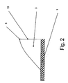
- FIG. 2 shows the part of the carrier sheet that remains after the cutting process 1 shown with the bead 3. In this example, the cut is along the Line 11 has been run.
- FIG. 3 shows a section of the bead 3 with the carrier sheet 1 in a top view.
- a cut line 13 is drawn in dashed lines and has a zigzag shape.
- the part 14 of the bead lying on the right of the cutting line 13 together with the associated carrier sheet 1 is cut away.
- the cutting line 13 can be inserted into the bead as desired by changing the angles ⁇ and ⁇ i +1.
- the angles ⁇ can be changed between 0 ° and 180 °.
- a cutting line is formed which runs along the center line 15 of the beads 3.
- the section line 13 is preferably placed in a range of the angles ⁇ between 120 ° and 180 °.
- FIG. 4 shows an embodiment in which the section line 13 undulating.
- the section line 13 undulating is the one to the right of the section line 13 Part 14 of the bead 3 and the carrier sheet 1 cut away.
- the sealing edge then runs along the section line 13.
- the arches 16 and 17 of the waves can be chosen arbitrarily.
Landscapes
- Engineering & Computer Science (AREA)
- General Engineering & Computer Science (AREA)
- Mechanical Engineering (AREA)
- Fuel Cell (AREA)
- Battery Mounting, Suspending (AREA)
Abstract
Description
Verschiedene Möglichkeiten von Dichtungsanordnungen sind hier bekannt.
Es zeigt:
- Figur 1
- das Trägerblatt mit einem aufgetragenen Wulst im Querschnitt,
- Figur 2
- das Trägerblatt mit einem verbliebenen Teil des Wulstes, nachdem ein Teil des Wulstes weggeschnitten ist,
- Figur 3
- einen Abschnitt des Trägerblatts mit dem Wulst in der Draufsicht,
- Figur 4
- einen weiteren Abschnitt des Trägerblatts mit einem Wulst.
Claims (14)
- Dichtungsanordnung an zwei einander zugewandten Flächen, dadurch gekennzeichnet, dass zwischen die abzudichtenden Flächen im Dichtungsbereich ein Trägerblatt (1) eingefügt ist, das auf wenigstens einer seiner Oberflächen (2) an vorgegebenen Positionen mit elastischem Dichtungsmaterial versehen ist.
- Dichtungsanordnung an zwei einander zugewandten Flächen nach Anspruch 1, dadurch gekennzeichnet, dass das elastomere Material als Wulst (3) auf das Trägerblatt (1) aufgetragen ist.
- Dichtungsanordnung an zwei einander zugewandten Flächen nach Anspruch 1 oder 2, dadurch gekennzeichnet, dass ein Teil (14) des Wulstes (3) einschließlich des mit diesem Teil (14) verbundenen Trägerblatts (1) weggeschnitten ist.
- Dichtungsanordnung an zwei einander zugewandten Flächen nach Anspruch 1 oder 2, dadurch gekennzeichnet, dass der Wulst (3) auf seinem Kammbereich mit einer Nut (4) versehen ist.
- Dichtungsanordnung an zwei einander zugewandten Flächen nach einem der Ansprüche 1 bis 4, dadurch gekennzeichnet, dass die Schnittlinie (10, 11, 13) oder die Nut (4) zickzackförmig oder wellenförmig verläuft.
- Dichtungsanordnung an zwei einander zugewandten Flächen nach Anspruch 5, dadurch gekennzeichnet, dass die Winkel (γ) der zickzackförmigen Schnittlinie (13) oder Nut (4) 10° bis 180° betragen.
- Dichtungsanordnung an zwei einander zugewandten Flächen nach Anspruch 5 oder 6, dadurch gekennzeichnet, dass die Schnittlinie (13) gleiche, sich wiederholende Abschnitte hat.
- Dichtungsanordnung an zwei einander zugewandten Flächen nach einem der Ansprüche 1 bis 7, dadurch gekennzeichnet, dass das Dichtungsmaterial ein Silikon, Ethylenpropylen-Dien-Kautschuk oder ein Fluor-Kautschuk ist.
- Dichtungsanordnung an zwei einander zugewandten Flächen nach Anspruch 1 oder 2, dadurch gekennzeichnet, dass das Trägerblatt (1) eine Folie ist.
- Dichtungsanordnung an zwei einander zugewandten Flächen nach Anspruch 9, dadurch gekennzeichnet, dass die Folie (1) eine Polymer-Elektrolyt-Membran einer elektrochemischen Brennstoffzelle ist.
- Dichtungsanordnung an zwei einander zugewandten Flächen nach Anspruch 10, dadurch gekennzeichnet, dass die abzudichtenden Flächen Verteilerplatten aus Graphit sind.
- Dichtungsanordnung an zwei einander zugewandten Flächen nach einem der Ansprüche 1 bis 11, dadurch gekennzeichnet, dass der Dichtungswulst (3) mit dem zugehörigen Trägerblatt (1) durch Vulkanisation oder Verkleben verbunden ist.
- Dichtungsanordnung an zwei einander zugewandten Flächen nach einem der Ansprüche 1 bis 11, dadurch gekennzeichnet, dass das Dichtungsmaterial im Siebdruckverfahren oder Raupen-Auftragsverfahren auf das Trägerblatt (1) aufgetragen ist.
- Dichtungsanordnung an zwei einander zugewandten Flächen nach einem der Ansprüche 1 bis 13, dadurch gekennzeichnet, dass die von dem Dichtungsmaterial bedeckte Fläche des Trägerblatts (1) vor dem Aufbringen des Dichtungsmaterials mit einem Binder beschichtet ist.
Applications Claiming Priority (2)
| Application Number | Priority Date | Filing Date | Title |
|---|---|---|---|
| DE10161197 | 2001-12-13 | ||
| DE10161197A DE10161197A1 (de) | 2001-12-13 | 2001-12-13 | Dichtungsanordnung an zwei einander zugewandten Flächen |
Publications (2)
| Publication Number | Publication Date |
|---|---|
| EP1319875A2 true EP1319875A2 (de) | 2003-06-18 |
| EP1319875A3 EP1319875A3 (de) | 2004-03-17 |
Family
ID=7709038
Family Applications (1)
| Application Number | Title | Priority Date | Filing Date |
|---|---|---|---|
| EP02014913A Withdrawn EP1319875A3 (de) | 2001-12-13 | 2002-07-05 | Dichtungsanordnung an zwei einander zugewandten Flächen |
Country Status (2)
| Country | Link |
|---|---|
| EP (1) | EP1319875A3 (de) |
| DE (1) | DE10161197A1 (de) |
Families Citing this family (1)
| Publication number | Priority date | Publication date | Assignee | Title |
|---|---|---|---|---|
| DE102021115559A1 (de) | 2021-06-16 | 2022-12-22 | Schaeffler Technologies AG & Co. KG | Brennstoffzelle |
Citations (2)
| Publication number | Priority date | Publication date | Assignee | Title |
|---|---|---|---|---|
| EP0752078A1 (de) | 1994-06-15 | 1997-01-08 | T & N TECHNOLOGY LIMITED | Wülste für flachdichtungen |
| DE19542475A1 (de) | 1995-11-15 | 1997-05-22 | Daimler Benz Ag | Integrierte Dichtung für eine PEM-Brennstoffzelle |
Family Cites Families (4)
| Publication number | Priority date | Publication date | Assignee | Title |
|---|---|---|---|---|
| US4898653A (en) * | 1988-09-26 | 1990-02-06 | The Dow Chemical Company | Combination electrolysis cell seal member and membrane tentering means |
| US5173373A (en) * | 1989-09-14 | 1992-12-22 | Yamaha Hatsudoki Kabushiki Kaisha | Gasket for fuel cell |
| JP3809491B2 (ja) * | 1997-10-29 | 2006-08-16 | アイシン高丘株式会社 | 燃料電池用セパレータ |
| JP4066117B2 (ja) * | 1999-06-11 | 2008-03-26 | Nok株式会社 | 燃料電池用ガスケット |
-
2001
- 2001-12-13 DE DE10161197A patent/DE10161197A1/de not_active Withdrawn
-
2002
- 2002-07-05 EP EP02014913A patent/EP1319875A3/de not_active Withdrawn
Patent Citations (2)
| Publication number | Priority date | Publication date | Assignee | Title |
|---|---|---|---|---|
| EP0752078A1 (de) | 1994-06-15 | 1997-01-08 | T & N TECHNOLOGY LIMITED | Wülste für flachdichtungen |
| DE19542475A1 (de) | 1995-11-15 | 1997-05-22 | Daimler Benz Ag | Integrierte Dichtung für eine PEM-Brennstoffzelle |
Also Published As
| Publication number | Publication date |
|---|---|
| EP1319875A3 (de) | 2004-03-17 |
| DE10161197A1 (de) | 2003-07-03 |
Similar Documents
| Publication | Publication Date | Title |
|---|---|---|
| DE3234969C2 (de) | Vakuumbetätigbarer Werkstückhalter | |
| DE69804471T2 (de) | Dichtung für elektrische verbinder, anwendung und verfahren zur herstellung | |
| EP1032065A2 (de) | Dichtungsanordnung für grossflächige dünne Teile | |
| DE10248531A1 (de) | Brennstoffzellensystem | |
| DE60009075T2 (de) | Wärmetauscherplatte | |
| DE3837830A1 (de) | Dichtung | |
| DE1918780C2 (de) | Verfahren und Vorrichtung zum Feinschneiden von Werkstücken aus Blech | |
| CH665133A5 (de) | Filtermembran mit abdichtung und verfahren zu ihrer herstellung. | |
| EP3123545B1 (de) | Dichtungsanordnung für eine elektrochemische vorrichtung | |
| DE102009016934A1 (de) | Brennstoffzelle, Brennstoffzellenstapel und Verfahren zum Abdichten einer Brennstoffzelle | |
| DE102017106645A1 (de) | Filterrahmen, Filtereinsatz und Montageverfahren für den Filtereinsatz | |
| DE102018115987A1 (de) | Verfahren zum Erzeugen eines Dichtelements an einer Gasdiffusionslage einer elektrochemischen Einheit und Baugruppe aus einer Gasdiffusionslage und einem Dichtelement | |
| DE102009018826A1 (de) | Plattenbauteil für ein Filterpressen-System | |
| EP0916241A1 (de) | Verfahren zum herstellen einer elektromagnetisch abschirmenden dichtung | |
| DE2519269A1 (de) | Formkonstruktion | |
| DE69313648T2 (de) | Dichtungsherstellung | |
| DE10161197A1 (de) | Dichtungsanordnung an zwei einander zugewandten Flächen | |
| DE102019217722B3 (de) | Anordnung elektrochemischer Zellen | |
| DE102013205220A1 (de) | Steuerplatte | |
| EP0175236A2 (de) | Vorrichtung zur Einführung eines Flachkabels | |
| DE19907938B4 (de) | Abdichtungselement für zwei oder mehrere Gehäuseteile einer pneumatischen Scheibenbremseinrichtung | |
| DE7520639U (de) | Filterplatte fuer plattenfilterpressen | |
| EP4480020A1 (de) | Zelllagentrennvorrichtung zum gleichzeitigen trennen von zelllagen eines zellstapels einer brennstoffzelle | |
| DE102012012749A1 (de) | Verfahren zur Herstellung einer Bipolarplatte einer Brennstoffzelle und Bipolarplatte | |
| DE10237019A1 (de) | Verfahren zur Herstellung von Dichtelementen sowie Dichtelement |
Legal Events
| Date | Code | Title | Description |
|---|---|---|---|
| PUAI | Public reference made under article 153(3) epc to a published international application that has entered the european phase |
Free format text: ORIGINAL CODE: 0009012 |
|
| 17P | Request for examination filed |
Effective date: 20020712 |
|
| AK | Designated contracting states |
Designated state(s): AT BE BG CH CY CZ DE DK EE ES FI FR GB GR IE IT LI LU MC NL PT SE SK TR |
|
| AX | Request for extension of the european patent |
Extension state: AL LT LV MK RO SI |
|
| PUAL | Search report despatched |
Free format text: ORIGINAL CODE: 0009013 |
|
| AK | Designated contracting states |
Kind code of ref document: A3 Designated state(s): AT BE BG CH CY CZ DE DK EE ES FI FR GB GR IE IT LI LU MC NL PT SE SK TR |
|
| AX | Request for extension of the european patent |
Extension state: AL LT LV MK RO SI |
|
| RIC1 | Information provided on ipc code assigned before grant |
Ipc: 7F 16J 15/10 B Ipc: 7H 01M 8/02 B Ipc: 7F 16J 15/02 A |
|
| 17Q | First examination report despatched |
Effective date: 20040521 |
|
| AKX | Designation fees paid |
Designated state(s): CH DE IT LI NL |
|
| STAA | Information on the status of an ep patent application or granted ep patent |
Free format text: STATUS: THE APPLICATION IS DEEMED TO BE WITHDRAWN |
|
| 18D | Application deemed to be withdrawn |
Effective date: 20041001 |