EP1318012A1 - Bewegliche transparente Verbundsysteme, Verfahren zu ihrer Herstellung und ihre Verwendung - Google Patents
Bewegliche transparente Verbundsysteme, Verfahren zu ihrer Herstellung und ihre Verwendung Download PDFInfo
- Publication number
- EP1318012A1 EP1318012A1 EP02026456A EP02026456A EP1318012A1 EP 1318012 A1 EP1318012 A1 EP 1318012A1 EP 02026456 A EP02026456 A EP 02026456A EP 02026456 A EP02026456 A EP 02026456A EP 1318012 A1 EP1318012 A1 EP 1318012A1
- Authority
- EP
- European Patent Office
- Prior art keywords
- parts
- connecting element
- transparent
- composite system
- thermoplastic
- Prior art date
- Legal status (The legal status is an assumption and is not a legal conclusion. Google has not performed a legal analysis and makes no representation as to the accuracy of the status listed.)
- Granted
Links
- 239000002131 composite material Substances 0.000 title claims abstract description 34
- 238000000034 method Methods 0.000 title claims abstract description 12
- 238000004519 manufacturing process Methods 0.000 title claims description 6
- 239000004417 polycarbonate Substances 0.000 claims abstract description 18
- 229920000515 polycarbonate Polymers 0.000 claims abstract description 17
- 229920001169 thermoplastic Polymers 0.000 claims abstract description 14
- 239000004416 thermosoftening plastic Substances 0.000 claims abstract description 13
- -1 polybutylene terephthalate Polymers 0.000 claims abstract description 10
- 229920002635 polyurethane Polymers 0.000 claims abstract description 7
- 239000004814 polyurethane Substances 0.000 claims abstract description 7
- 239000000203 mixture Substances 0.000 claims abstract description 6
- FERIUCNNQQJTOY-UHFFFAOYSA-M Butyrate Chemical compound CCCC([O-])=O FERIUCNNQQJTOY-UHFFFAOYSA-M 0.000 claims abstract description 4
- FERIUCNNQQJTOY-UHFFFAOYSA-N Butyric acid Natural products CCCC(O)=O FERIUCNNQQJTOY-UHFFFAOYSA-N 0.000 claims abstract description 4
- 239000004952 Polyamide Substances 0.000 claims abstract description 4
- 239000005038 ethylene vinyl acetate Substances 0.000 claims abstract description 4
- 229920001200 poly(ethylene-vinyl acetate) Polymers 0.000 claims abstract description 4
- 229920002647 polyamide Polymers 0.000 claims abstract description 4
- 229920001707 polybutylene terephthalate Polymers 0.000 claims abstract description 4
- 239000005020 polyethylene terephthalate Substances 0.000 claims abstract description 4
- 229920000139 polyethylene terephthalate Polymers 0.000 claims abstract description 4
- 230000002441 reversible effect Effects 0.000 claims abstract description 4
- 229920002554 vinyl polymer Polymers 0.000 claims abstract description 4
- 239000004433 Thermoplastic polyurethane Substances 0.000 claims description 19
- 229920002803 thermoplastic polyurethane Polymers 0.000 claims description 19
- 238000001746 injection moulding Methods 0.000 claims description 4
- 125000001931 aliphatic group Chemical group 0.000 claims description 3
- 238000007765 extrusion coating Methods 0.000 claims description 3
- 239000007787 solid Substances 0.000 claims description 3
- 229920001756 Polyvinyl chloride acetate Polymers 0.000 claims description 2
- 238000010276 construction Methods 0.000 claims description 2
- 238000001125 extrusion Methods 0.000 claims description 2
- 238000003475 lamination Methods 0.000 claims description 2
- 239000004800 polyvinyl chloride Substances 0.000 claims description 2
- 239000012815 thermoplastic material Substances 0.000 claims 1
- 229920003229 poly(methyl methacrylate) Polymers 0.000 abstract 2
- 239000004926 polymethyl methacrylate Substances 0.000 abstract 2
- 229920003023 plastic Polymers 0.000 description 16
- 239000004033 plastic Substances 0.000 description 15
- 239000000853 adhesive Substances 0.000 description 2
- 230000001070 adhesive effect Effects 0.000 description 2
- 238000005516 engineering process Methods 0.000 description 2
- 238000002347 injection Methods 0.000 description 2
- 239000007924 injection Substances 0.000 description 2
- 239000000463 material Substances 0.000 description 2
- 229920000642 polymer Polymers 0.000 description 2
- 238000005452 bending Methods 0.000 description 1
- 229920002678 cellulose Polymers 0.000 description 1
- 229920001971 elastomer Polymers 0.000 description 1
- 239000000806 elastomer Substances 0.000 description 1
- 239000011521 glass Substances 0.000 description 1
- 239000007788 liquid Substances 0.000 description 1
- 238000002844 melting Methods 0.000 description 1
- 230000008018 melting Effects 0.000 description 1
- 229920001692 polycarbonate urethane Polymers 0.000 description 1
- 229920000728 polyester Polymers 0.000 description 1
- 229920000098 polyolefin Polymers 0.000 description 1
- 229920006324 polyoxymethylene Polymers 0.000 description 1
- 238000003825 pressing Methods 0.000 description 1
- 239000005336 safety glass Substances 0.000 description 1
- 239000002699 waste material Substances 0.000 description 1
- 238000003466 welding Methods 0.000 description 1
Images
Classifications
-
- B—PERFORMING OPERATIONS; TRANSPORTING
- B32—LAYERED PRODUCTS
- B32B—LAYERED PRODUCTS, i.e. PRODUCTS BUILT-UP OF STRATA OF FLAT OR NON-FLAT, e.g. CELLULAR OR HONEYCOMB, FORM
- B32B27/00—Layered products comprising a layer of synthetic resin
- B32B27/06—Layered products comprising a layer of synthetic resin as the main or only constituent of a layer, which is next to another layer of the same or of a different material
- B32B27/08—Layered products comprising a layer of synthetic resin as the main or only constituent of a layer, which is next to another layer of the same or of a different material of synthetic resin
-
- C—CHEMISTRY; METALLURGY
- C08—ORGANIC MACROMOLECULAR COMPOUNDS; THEIR PREPARATION OR CHEMICAL WORKING-UP; COMPOSITIONS BASED THEREON
- C08J—WORKING-UP; GENERAL PROCESSES OF COMPOUNDING; AFTER-TREATMENT NOT COVERED BY SUBCLASSES C08B, C08C, C08F, C08G or C08H
- C08J5/00—Manufacture of articles or shaped materials containing macromolecular substances
- C08J5/12—Bonding of a preformed macromolecular material to the same or other solid material such as metal, glass, leather, e.g. using adhesives
-
- B—PERFORMING OPERATIONS; TRANSPORTING
- B32—LAYERED PRODUCTS
- B32B—LAYERED PRODUCTS, i.e. PRODUCTS BUILT-UP OF STRATA OF FLAT OR NON-FLAT, e.g. CELLULAR OR HONEYCOMB, FORM
- B32B27/00—Layered products comprising a layer of synthetic resin
- B32B27/40—Layered products comprising a layer of synthetic resin comprising polyurethanes
-
- B—PERFORMING OPERATIONS; TRANSPORTING
- B60—VEHICLES IN GENERAL
- B60J—WINDOWS, WINDSCREENS, NON-FIXED ROOFS, DOORS, OR SIMILAR DEVICES FOR VEHICLES; REMOVABLE EXTERNAL PROTECTIVE COVERINGS SPECIALLY ADAPTED FOR VEHICLES
- B60J7/00—Non-fixed roofs; Roofs with movable panels, e.g. rotary sunroofs
-
- F—MECHANICAL ENGINEERING; LIGHTING; HEATING; WEAPONS; BLASTING
- F24—HEATING; RANGES; VENTILATING
- F24S—SOLAR HEAT COLLECTORS; SOLAR HEAT SYSTEMS
- F24S20/00—Solar heat collectors specially adapted for particular uses or environments
- F24S20/50—Rollable or foldable solar heat collector modules
- F24S20/55—Rollable or foldable solar heat collector modules made of flexible materials
-
- F—MECHANICAL ENGINEERING; LIGHTING; HEATING; WEAPONS; BLASTING
- F24—HEATING; RANGES; VENTILATING
- F24S—SOLAR HEAT COLLECTORS; SOLAR HEAT SYSTEMS
- F24S25/00—Arrangement of stationary mountings or supports for solar heat collector modules
- F24S25/40—Arrangement of stationary mountings or supports for solar heat collector modules using plate-like mounting elements, e.g. profiled or corrugated plates; Plate-like module frames
-
- E—FIXED CONSTRUCTIONS
- E05—LOCKS; KEYS; WINDOW OR DOOR FITTINGS; SAFES
- E05D—HINGES OR SUSPENSION DEVICES FOR DOORS, WINDOWS OR WINGS
- E05D1/00—Pinless hinges; Substitutes for hinges
- E05D1/02—Pinless hinges; Substitutes for hinges made of one piece
-
- E—FIXED CONSTRUCTIONS
- E05—LOCKS; KEYS; WINDOW OR DOOR FITTINGS; SAFES
- E05Y—INDEXING SCHEME ASSOCIATED WITH SUBCLASSES E05D AND E05F, RELATING TO CONSTRUCTION ELEMENTS, ELECTRIC CONTROL, POWER SUPPLY, POWER SIGNAL OR TRANSMISSION, USER INTERFACES, MOUNTING OR COUPLING, DETAILS, ACCESSORIES, AUXILIARY OPERATIONS NOT OTHERWISE PROVIDED FOR, APPLICATION THEREOF
- E05Y2900/00—Application of doors, windows, wings or fittings thereof
- E05Y2900/50—Application of doors, windows, wings or fittings thereof for vehicles
- E05Y2900/53—Type of wing
- E05Y2900/542—Roof panels
-
- F—MECHANICAL ENGINEERING; LIGHTING; HEATING; WEAPONS; BLASTING
- F24—HEATING; RANGES; VENTILATING
- F24S—SOLAR HEAT COLLECTORS; SOLAR HEAT SYSTEMS
- F24S30/00—Arrangements for moving or orienting solar heat collector modules
- F24S2030/10—Special components
- F24S2030/16—Hinged elements; Pin connections
-
- F—MECHANICAL ENGINEERING; LIGHTING; HEATING; WEAPONS; BLASTING
- F24—HEATING; RANGES; VENTILATING
- F24S—SOLAR HEAT COLLECTORS; SOLAR HEAT SYSTEMS
- F24S80/00—Details, accessories or component parts of solar heat collectors not provided for in groups F24S10/00-F24S70/00
- F24S2080/01—Selection of particular materials
- F24S2080/015—Plastics
-
- Y—GENERAL TAGGING OF NEW TECHNOLOGICAL DEVELOPMENTS; GENERAL TAGGING OF CROSS-SECTIONAL TECHNOLOGIES SPANNING OVER SEVERAL SECTIONS OF THE IPC; TECHNICAL SUBJECTS COVERED BY FORMER USPC CROSS-REFERENCE ART COLLECTIONS [XRACs] AND DIGESTS
- Y02—TECHNOLOGIES OR APPLICATIONS FOR MITIGATION OR ADAPTATION AGAINST CLIMATE CHANGE
- Y02B—CLIMATE CHANGE MITIGATION TECHNOLOGIES RELATED TO BUILDINGS, e.g. HOUSING, HOUSE APPLIANCES OR RELATED END-USER APPLICATIONS
- Y02B10/00—Integration of renewable energy sources in buildings
- Y02B10/20—Solar thermal
-
- Y—GENERAL TAGGING OF NEW TECHNOLOGICAL DEVELOPMENTS; GENERAL TAGGING OF CROSS-SECTIONAL TECHNOLOGIES SPANNING OVER SEVERAL SECTIONS OF THE IPC; TECHNICAL SUBJECTS COVERED BY FORMER USPC CROSS-REFERENCE ART COLLECTIONS [XRACs] AND DIGESTS
- Y02—TECHNOLOGIES OR APPLICATIONS FOR MITIGATION OR ADAPTATION AGAINST CLIMATE CHANGE
- Y02E—REDUCTION OF GREENHOUSE GAS [GHG] EMISSIONS, RELATED TO ENERGY GENERATION, TRANSMISSION OR DISTRIBUTION
- Y02E10/00—Energy generation through renewable energy sources
- Y02E10/40—Solar thermal energy, e.g. solar towers
- Y02E10/47—Mountings or tracking
-
- Y—GENERAL TAGGING OF NEW TECHNOLOGICAL DEVELOPMENTS; GENERAL TAGGING OF CROSS-SECTIONAL TECHNOLOGIES SPANNING OVER SEVERAL SECTIONS OF THE IPC; TECHNICAL SUBJECTS COVERED BY FORMER USPC CROSS-REFERENCE ART COLLECTIONS [XRACs] AND DIGESTS
- Y02—TECHNOLOGIES OR APPLICATIONS FOR MITIGATION OR ADAPTATION AGAINST CLIMATE CHANGE
- Y02P—CLIMATE CHANGE MITIGATION TECHNOLOGIES IN THE PRODUCTION OR PROCESSING OF GOODS
- Y02P80/00—Climate change mitigation technologies for sector-wide applications
- Y02P80/20—Climate change mitigation technologies for sector-wide applications using renewable energy
-
- Y—GENERAL TAGGING OF NEW TECHNOLOGICAL DEVELOPMENTS; GENERAL TAGGING OF CROSS-SECTIONAL TECHNOLOGIES SPANNING OVER SEVERAL SECTIONS OF THE IPC; TECHNICAL SUBJECTS COVERED BY FORMER USPC CROSS-REFERENCE ART COLLECTIONS [XRACs] AND DIGESTS
- Y10—TECHNICAL SUBJECTS COVERED BY FORMER USPC
- Y10T—TECHNICAL SUBJECTS COVERED BY FORMER US CLASSIFICATION
- Y10T428/00—Stock material or miscellaneous articles
- Y10T428/19—Sheets or webs edge spliced or joined
- Y10T428/192—Sheets or webs coplanar
- Y10T428/195—Beveled, stepped, or skived in thickness
-
- Y—GENERAL TAGGING OF NEW TECHNOLOGICAL DEVELOPMENTS; GENERAL TAGGING OF CROSS-SECTIONAL TECHNOLOGIES SPANNING OVER SEVERAL SECTIONS OF THE IPC; TECHNICAL SUBJECTS COVERED BY FORMER USPC CROSS-REFERENCE ART COLLECTIONS [XRACs] AND DIGESTS
- Y10—TECHNICAL SUBJECTS COVERED BY FORMER USPC
- Y10T—TECHNICAL SUBJECTS COVERED BY FORMER US CLASSIFICATION
- Y10T428/00—Stock material or miscellaneous articles
- Y10T428/19—Sheets or webs edge spliced or joined
- Y10T428/192—Sheets or webs coplanar
- Y10T428/197—Sheets or webs coplanar with noncoplanar reinforcement
-
- Y—GENERAL TAGGING OF NEW TECHNOLOGICAL DEVELOPMENTS; GENERAL TAGGING OF CROSS-SECTIONAL TECHNOLOGIES SPANNING OVER SEVERAL SECTIONS OF THE IPC; TECHNICAL SUBJECTS COVERED BY FORMER USPC CROSS-REFERENCE ART COLLECTIONS [XRACs] AND DIGESTS
- Y10—TECHNICAL SUBJECTS COVERED BY FORMER USPC
- Y10T—TECHNICAL SUBJECTS COVERED BY FORMER US CLASSIFICATION
- Y10T428/00—Stock material or miscellaneous articles
- Y10T428/24—Structurally defined web or sheet [e.g., overall dimension, etc.]
- Y10T428/24942—Structurally defined web or sheet [e.g., overall dimension, etc.] including components having same physical characteristic in differing degree
-
- Y—GENERAL TAGGING OF NEW TECHNOLOGICAL DEVELOPMENTS; GENERAL TAGGING OF CROSS-SECTIONAL TECHNOLOGIES SPANNING OVER SEVERAL SECTIONS OF THE IPC; TECHNICAL SUBJECTS COVERED BY FORMER USPC CROSS-REFERENCE ART COLLECTIONS [XRACs] AND DIGESTS
- Y10—TECHNICAL SUBJECTS COVERED BY FORMER USPC
- Y10T—TECHNICAL SUBJECTS COVERED BY FORMER US CLASSIFICATION
- Y10T428/00—Stock material or miscellaneous articles
- Y10T428/26—Web or sheet containing structurally defined element or component, the element or component having a specified physical dimension
Definitions
- the present invention relates to transparent, light-stable, movable composite systems, which consists of a combination of rigid parts made of transparent, thermoplastic Plastic, preferably polycarbonate, with flexible connecting elements made of transparent, light-stable, thermoplastic polyurethane (TPU) exist, a process for their production and their use.
- transparent, light-stable, movable composite systems which consists of a combination of rigid parts made of transparent, thermoplastic Plastic, preferably polycarbonate, with flexible connecting elements made of transparent, light-stable, thermoplastic polyurethane (TPU) exist, a process for their production and their use.
- TPU thermoplastic polyurethane
- polycarbonates are made of transparency, toughness, Heat resistance and good electrical properties of great technical Importance.
- An overview of the manufacture, properties and Applications of polycarbonates are e.g. in the plastic manual (G. Becker, D. Braun), volume 3/1 "polycarbonates, polyacetals, polyester, cellulose esters", Kunststoff, Vienna, Carl Hanser Verlag, 1992 or in "Handbook of Polycarbonate Science and Technology "(D. Legrand, J. Bendler), New York, Basel, Marcel Dekker, given in 2000.
- TPU Thermoplastic polyurethanes
- film hinges are movable, insoluble, integral Connections created by creating an extreme cross-sectional taper on injection molded parts.
- film hinges consist of the same material as the rigid parts that connect the film hinge to each other. The flexibility arises exclusively through an extreme reduction in waste.
- partially crystalline polymers preferably polyolefins, which are often not completely transparent.
- the object of the present invention was to provide transparent, light-stable, movable, thermoplastic composite systems made of transparent plastic are available too put.
- thermoplastic polyurethane This task could be solved by using the plastic parts a thermoplastic polyurethane.
- the present invention therefore relates to movable, transparent, light-stable composite systems consisting of at least two rigid parts (1) one transparent, light-stable, thermoplastic from the group consisting of polycarbonate, polymethylene methacrylate, polyvinyl butyrate, polyamide, Polybutylene terephthalate, polyethylene terephthalate, polyvinyl chloride and ethylene vinyl acetate copolymer, Blends and mixtures thereof, each with an edge by means of a flexible connecting element (2) made of a thermoplastic, transparent, light stable polyurethane (TPU) with a turbidity of 0 to 20% at a Thickness of 1 mm (according to ISO 14782 / ASTM D 1003-97), a Shore hardness of 60 Shore A to 70 Shore D (according to ISO 868 / DIN 53 505) and a yellowness Index from 0 to 25 with a thickness of 1 mm (according to DIN 6167 / ASTM E 313-00) are connected to each other, wherein the connecting element
- the TPU used should have the following properties: transparent, light-stable and flexible.
- Thermoplastic polyurethanes that have these properties e.g. in EP-A 1 090 940 and are particularly preferred.
- the parts (1) preferably consist of transparent polycarbonate.
- the plastic parts (1) can be solid plates or other flat structures, such as e.g. Be hollow chamber panels, but also three-dimensional, transparent molded parts, through flexible connecting elements made of transparent, thermoplastic Polyurethane are connected to each other and thereby an overall movable, result in a flexible, transparent composite system.
- the parts (1) preferably have a thickness of 50 ⁇ m to 2 mm.
- the connecting element (2) preferably consists of an aliphatic thermoplastic Polyurethane.
- the connecting element (2) preferably has a thickness of 100 ⁇ m to 2 mm on.
- the connecting element (2) is preferably located over a part or over the complete area of the parts (1).
- the transparent, movable composite systems according to the invention preferably exist from at least two transparent polycarbonate sheets, which are separated by the flexible connecting element made of transparent, thermoplastic polyurethane are interconnected.
- the connecting element can either partially or be applied over the entire surface of the polycarbonate sheets.
- the connecting element can be on one side or on both sides on the polycarbonate sheets be upset.
- Polycarbonate sheets include not only solid sheets, but also twin-wall sheets to understand.
- the plates can not only be flat, but also be three-dimensional, e.g. Corrugated sheets made of polycarbonate.
- the composite systems according to the invention are preferably transparent, movable Two-component composites, in which both the plastic parts and the flexible connecting element (2) made of thermoplastic, aliphatic polyurethane are transparent.
- the parts (1) preferably consist of polycarbonate.
- thermoplastic Polyurethane makes of thermoplastic Polyurethane is its transparency and its very high mechanical resilience, especially the alternating bending strength compared to other hinges, e.g. Film hinges.
- the connecting element (2) can be used with the plastic parts by using an adhesive (1) be connected.
- the adhesive can be on the surface of the connecting element and / or applied to the surface of the plastic parts.
- the connecting element (2) can also be laminated with the plastic parts (1) be connected. This is done by continuous or discontinuous pressing a composite under the influence of elevated temperature and / or pressure made between the plastic parts and the connecting element. To achieve The plastic part should adhere well to the element (2) on the plastic part kept at a temperature above 50 ° C during the manufacturing process become. Also special lamination processing techniques, e.g. Radio frequency (RF) -Versch wellung can preferably be used. This technique is based on a local melting caused by the application of a high-frequency field of the polymer, with adhesion occurring after the material has solidified. RF welding e.g. in the plastic paperback (H. Sachtling), 24th edition, Hanser-Verlag, 1989, pages 196-197.
- RF Radio frequency
- the flexible composite systems according to the invention can also be produced by two-component injection molding produce.
- an at least two-part molded part is made injection molded thermoplastic, which is made by a in the same tool Element made of thermoplastic polyurethane is connected.
- the two-component injection molding is, for example, in G. Ehrenstein, K. Kuhmann, multi-component injection molding - Technology, process and composite properties- Düsseldorf 1997 described.
- the composite systems according to the invention can also be co-extruded or can be produced by extrusion coating.
- co-extrusion both the thermoplastic as well as the TPU in liquid form either in Extruder head or merged shortly behind.
- extrusion coating the molten TPU either in whole or in part across the width of the plastic parts applied.
- the composite systems according to the invention are preferred as building and construction elements used, e.g. foldable roofs, foldable blinds.
- the advantage Such flexible composite systems is that they are very compact when folded take up little space and are therefore easy to transport. Moreover they can be unfolded again without any effort.
- the composite systems according to the invention can e.g. also as movable, adjustable Carrier for photovoltaic solar panels can be used.
- the folding process in the composite systems is reversible.
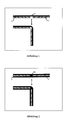
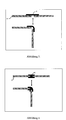
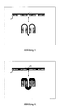
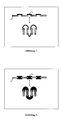
- Each of the pictures 1 to 8 shows the cross section through a composite system in the unfolded state and when folded.
- (1) is a plastic plate and (2) is the TPU connector.
Landscapes
- Engineering & Computer Science (AREA)
- Chemical & Material Sciences (AREA)
- Mechanical Engineering (AREA)
- Life Sciences & Earth Sciences (AREA)
- General Engineering & Computer Science (AREA)
- Combustion & Propulsion (AREA)
- Thermal Sciences (AREA)
- Sustainable Energy (AREA)
- Sustainable Development (AREA)
- Physics & Mathematics (AREA)
- Health & Medical Sciences (AREA)
- Organic Chemistry (AREA)
- Polymers & Plastics (AREA)
- Medicinal Chemistry (AREA)
- Chemical Kinetics & Catalysis (AREA)
- Manufacturing & Machinery (AREA)
- Materials Engineering (AREA)
- Laminated Bodies (AREA)
- Injection Moulding Of Plastics Or The Like (AREA)
- Polymerisation Methods In General (AREA)
- Manufacture Of Macromolecular Shaped Articles (AREA)
- Compositions Of Macromolecular Compounds (AREA)
- Lining Or Joining Of Plastics Or The Like (AREA)
Abstract
Description
Claims (17)
- Lichtstabiles, transparentes Verbundsystem bestehend aus mindestens zwei starren Teilen (1) eines transparenten, lichtstabilen, thermoplastischen Kunststoffes aus der Gruppe bestehend aus Polycarbonat, Polymethylenmethacrylat, Polyvinylbutyrat, Polyamid, Polybutylenterephthalat, Polyethylenterephthalat, Polyvinylchlorid und Ethylenvinylacetat-Copolymer, Blends und Gemischen davon, die jeweils über eine Kante mittels eines flexiblen Verbindungselementes (2) aus einem thermoplastischen, transparenten, lichtstabilen Polyurethan (TPU) mit einer Trübung von 0 bis 20 % bei einer Dicke von 1 mm (nach ISO 14782/ASTM D 1003-97), einer Shore-Härte von 60 Shore A bis 70 Shore D (gemäß ISO 868/DIN 53-505) und einem Yellowness Index von 0 bis 25 bei einer Dicke von 1 mm (gemäß DIN 6167/ASTM E 313-00) miteinander verbunden sind, wobei das Verbindungselement eine reversible, um bis zu 180° verformbare Knickstelle bildet.
- Verbundsystem nach Anspruch 1, dadurch gekennzeichnet, dass es sich bei dem transparenten, thermoplastischen Kunststoff für die Teile (1) um transparentes Polycarbonat handelt.
- Verbundsystem nach Anspruch 1, dadurch gekennzeichnet, dass es sich bei den Teilen (1) um Flächengebilde handelt.
- Verbundsystem gemäß Anspruch 3, dadurch gekennzeichnet, dass die Teile (1) eine Dicke von 50 µm bis 2 mm aufweisen.
- Verbundsystem nach Anspruch 1, dadurch gekennzeichnet, dass es sich bei den Teilen (1) um massive Platten handelt.
- Verbundsystem nach Anspruch 1, dadurch gekennzeichnet, dass es sich bei den Teilen (1) um Hohlkammerplatten handelt.
- Verbundsystem nach Anspruch 1, dadurch gekennzeichnet, dass es sich bei den Teilen (1) um dreidimensionale Teile handelt.
- Verbundsystem gemäß Anspruch 1, dadurch gekennzeichnet, dass das Verbindungselement (2) aus einem aliphatischen thermoplastischen Polyurethan besteht.
- Verbundsystem gemäß Anspruch 1, dadurch gekennzeichnet, dass das Verbindungselement (2) eine Dicke von 100 µm bis 2 mm aufweist.
- Verbundsystem gemäß Anspruch 1, dadurch gekennzeichnet, dass sich das Verbindungselement (2) über einem Teil oder über der vollständigen Fläche der Teile (1) befindet.
- Verfahren zur Herstellung der Verbundsysteme gemäß der Ansprüche 1 bis 10, dadurch gekennzeichnet, dass die Teile (1) mit dem Verbindungselement (2) verbunden werden.
- Verfahren gemäß Anspruch 11, dadurch gekennzeichnet, dass die Teile (1) mit dem Verbindungselement (2) verklebt werden.
- Verfahren gemäß Anspruch 11, dadurch gekennzeichnet, dass das Verbindungselement (2) durch Zweikomponentenspritzguss auf die Teile (1) aufgebracht wird.
- Verfahren gemäß Anspruch 11, dadurch gekennzeichnet, dass das Verbindungselement (2) durch kontinuierliche oder diskontinuierliche Laminierung auf die Teile (1) aufgebracht wird.
- Verfahren gemäß Anspruch 11, dadurch gekennzeichnet, dass das Verbindungselement (2) durch Co-Extrusion auf die Teile (1) aufgebracht wird.
- Verfahren gemäß Anspruch 11, dadurch gekennzeichnet, dass das Verbindungselement (2) durch Extrusionsbeschichtung auf die Teile (1) aufgebracht wird.
- Verwendung der Verbundsysteme gemäß der Ansprüche 1 bis 10 als Konstruktions- oder Bauelemente und als ausrichtbare, bewegliche Träger für photovoltaische Sonnenkollektoren.
Applications Claiming Priority (2)
| Application Number | Priority Date | Filing Date | Title |
|---|---|---|---|
| DE10160571 | 2001-12-10 | ||
| DE10160571 | 2001-12-10 |
Publications (2)
| Publication Number | Publication Date |
|---|---|
| EP1318012A1 true EP1318012A1 (de) | 2003-06-11 |
| EP1318012B1 EP1318012B1 (de) | 2005-07-27 |
Family
ID=7708650
Family Applications (1)
| Application Number | Title | Priority Date | Filing Date |
|---|---|---|---|
| EP02026456A Expired - Lifetime EP1318012B1 (de) | 2001-12-10 | 2002-11-27 | Bewegliche transparente Verbundsysteme, Verfahren zu ihrer Herstellung und ihre Verwendung |
Country Status (12)
| Country | Link |
|---|---|
| US (1) | US6713145B2 (de) |
| EP (1) | EP1318012B1 (de) |
| JP (1) | JP2003200493A (de) |
| KR (1) | KR20030047820A (de) |
| CN (1) | CN1424194A (de) |
| AT (1) | ATE300424T1 (de) |
| BR (1) | BR0205158A (de) |
| CA (1) | CA2413391A1 (de) |
| DE (1) | DE50203738D1 (de) |
| MX (1) | MXPA02012154A (de) |
| NZ (1) | NZ523037A (de) |
| ZA (1) | ZA200209943B (de) |
Cited By (5)
| Publication number | Priority date | Publication date | Assignee | Title |
|---|---|---|---|---|
| EP2085716A2 (de) | 2008-02-01 | 2009-08-05 | Michael Rinner | Solarwanne |
| WO2009146742A1 (en) * | 2008-06-04 | 2009-12-10 | Ems-Patent Ag | Sealing strips for vehicle windows |
| FR2958022A1 (fr) * | 2010-03-26 | 2011-09-30 | Alain Bivas | Dispositif pliable de concentration d'un faisceau de rayonnement electromagnetique et appareil de cuisson solaire comprenant un tel dispositif |
| WO2011121048A3 (en) * | 2010-03-30 | 2011-12-22 | Siemens Aktiengesellschaft | Hinge for a solar support structure, arrangement with the hinge and method for manufacturing the arrangement |
| EP2348264B1 (de) * | 2010-01-19 | 2013-01-16 | Hafenbahn GmbH & Co. KG | Platte zur Errichtung einer Vorrichtung zur Anordnung von Solarpaneelen und/oder Wärmekollektoren auf einem Untergrund, eine daraus errichtete Vorrichtung, die Verwendung einer Platte sowie ein Verfahren zur Errichtung einer Vorrichtung zur Anordnung von Solarpaneelen und/oder Wärmekollektoren auf einem Untergrund |
Families Citing this family (18)
| Publication number | Priority date | Publication date | Assignee | Title |
|---|---|---|---|---|
| JP2006187961A (ja) * | 2005-01-06 | 2006-07-20 | Gifu Plast Ind Co Ltd | 組み立て箱のインモールド成形による成形法 |
| DE102006029613A1 (de) | 2006-06-26 | 2007-12-27 | Röhm Gmbh | Transparenter Kunststoff-Verbund |
| CN101408343B (zh) * | 2007-10-12 | 2010-07-21 | 曹树梁 | 一种多孔陶瓷板纵列的密封连接方法 |
| US20100015456A1 (en) | 2008-07-16 | 2010-01-21 | Eastman Chemical Company | Thermoplastic formulations for enhanced paintability toughness and melt process ability |
| CA2714705C (en) * | 2009-09-09 | 2018-01-23 | Firestone Building Products Company, Llc | Thermoplastic flashing laminate |
| CN102626933A (zh) * | 2012-04-10 | 2012-08-08 | 上海奔腾电工有限公司 | 一种剃须刀头机构 |
| US8691915B2 (en) | 2012-04-23 | 2014-04-08 | Sabic Innovative Plastics Ip B.V. | Copolymers and polymer blends having improved refractive indices |
| CN102856403B (zh) * | 2012-10-08 | 2015-04-22 | 深圳市创益科技发展有限公司 | 一种柔性太阳能电池组件阵列及其封装方法 |
| US20150266275A1 (en) * | 2012-10-10 | 2015-09-24 | Basf Se | Interception device made from thermoplastic polyurethane |
| US8865261B2 (en) | 2012-12-06 | 2014-10-21 | Eastman Chemical Company | Extrusion coating of elongated substrates |
| US9744707B2 (en) | 2013-10-18 | 2017-08-29 | Eastman Chemical Company | Extrusion-coated structural members having extruded profile members |
| US9920526B2 (en) | 2013-10-18 | 2018-03-20 | Eastman Chemical Company | Coated structural members having improved resistance to cracking |
| US20150110986A1 (en) * | 2013-10-18 | 2015-04-23 | Eastman Chemical Company | Extrusion-coated structural systems with coating-coupled members |
| CN105333634B (zh) * | 2014-06-12 | 2017-10-13 | 青岛经济技术开发区海尔热水器有限公司 | 太阳能热水器支架折叠结构及太阳能热水器 |
| BR112018068248A2 (pt) * | 2016-03-11 | 2019-04-02 | Masonite Corporation | dispositivos e métodos para montagem de batentes de portas |
| US10870263B2 (en) | 2017-05-31 | 2020-12-22 | Bay Materials, Llc | Dual shell dental appliance and material constructions |
| KR20220007734A (ko) * | 2019-05-16 | 2022-01-18 | 사빅 글로벌 테크놀러지스 비.브이. | 기존 윈도우 프레임용 윈도우 프레임 인서트 및 그의 사용 방법 |
| JP7461248B2 (ja) * | 2020-08-13 | 2024-04-03 | 旭化成株式会社 | 積層体 |
Citations (3)
| Publication number | Priority date | Publication date | Assignee | Title |
|---|---|---|---|---|
| EP0279346A2 (de) * | 1987-02-19 | 1988-08-24 | Linde Aktiengesellschaft | Kühlmöbel |
| DE19510637C1 (de) * | 1995-03-23 | 1996-07-25 | Franz Schneider Kg Inh Dr Fran | Absperreinrichtung |
| DE19934269A1 (de) * | 1999-07-21 | 2001-01-25 | Behr Gmbh & Co | Steuerklappe zum Öffnen oder Schließen eines Luftführungskanales |
Family Cites Families (5)
| Publication number | Priority date | Publication date | Assignee | Title |
|---|---|---|---|---|
| DE3201849A1 (de) * | 1982-01-22 | 1983-08-04 | Vereinigte Glaswerke Gmbh, 5100 Aachen | Flexible sichtscheibe aus kunststoff, insbesondere faltbare heckscheibe fuer ein faltbares kabrio-verdeck |
| GB2127742A (en) * | 1982-09-30 | 1984-04-18 | Perstorp Warerite Limited | Method of shaping a laminated product |
| US5348791A (en) * | 1988-05-04 | 1994-09-20 | W. R. Grace Limited | Foldable waterproofing structure |
| DE19923683C2 (de) * | 1999-05-22 | 2001-10-18 | Schott Glas | Glastastatur und deren Verwendung |
| US6294638B1 (en) * | 1999-10-08 | 2001-09-25 | Bayer Corporation | Soft, transparent and processable thermoplastic polyurethane |
-
2002
- 2002-11-27 AT AT02026456T patent/ATE300424T1/de not_active IP Right Cessation
- 2002-11-27 EP EP02026456A patent/EP1318012B1/de not_active Expired - Lifetime
- 2002-11-27 DE DE50203738T patent/DE50203738D1/de not_active Expired - Fee Related
- 2002-12-03 CA CA002413391A patent/CA2413391A1/en not_active Abandoned
- 2002-12-06 NZ NZ523037A patent/NZ523037A/en unknown
- 2002-12-06 US US10/313,563 patent/US6713145B2/en not_active Expired - Fee Related
- 2002-12-09 MX MXPA02012154A patent/MXPA02012154A/es unknown
- 2002-12-09 ZA ZA200209943A patent/ZA200209943B/xx unknown
- 2002-12-09 JP JP2002356684A patent/JP2003200493A/ja active Pending
- 2002-12-09 KR KR1020020077696A patent/KR20030047820A/ko not_active Application Discontinuation
- 2002-12-10 BR BR0205158-3A patent/BR0205158A/pt not_active Application Discontinuation
- 2002-12-10 CN CN02154089A patent/CN1424194A/zh active Pending
Patent Citations (3)
| Publication number | Priority date | Publication date | Assignee | Title |
|---|---|---|---|---|
| EP0279346A2 (de) * | 1987-02-19 | 1988-08-24 | Linde Aktiengesellschaft | Kühlmöbel |
| DE19510637C1 (de) * | 1995-03-23 | 1996-07-25 | Franz Schneider Kg Inh Dr Fran | Absperreinrichtung |
| DE19934269A1 (de) * | 1999-07-21 | 2001-01-25 | Behr Gmbh & Co | Steuerklappe zum Öffnen oder Schließen eines Luftführungskanales |
Cited By (8)
| Publication number | Priority date | Publication date | Assignee | Title |
|---|---|---|---|---|
| EP2085716A2 (de) | 2008-02-01 | 2009-08-05 | Michael Rinner | Solarwanne |
| WO2009146742A1 (en) * | 2008-06-04 | 2009-12-10 | Ems-Patent Ag | Sealing strips for vehicle windows |
| CN102056758A (zh) * | 2008-06-04 | 2011-05-11 | 埃姆斯·帕特恩特股份有限公司 | 车窗密封条 |
| CN102056758B (zh) * | 2008-06-04 | 2013-07-10 | 埃姆斯·帕特恩特股份有限公司 | 车窗密封条及采用热塑性塑料制造该车窗密封条的方法 |
| EP2348264B1 (de) * | 2010-01-19 | 2013-01-16 | Hafenbahn GmbH & Co. KG | Platte zur Errichtung einer Vorrichtung zur Anordnung von Solarpaneelen und/oder Wärmekollektoren auf einem Untergrund, eine daraus errichtete Vorrichtung, die Verwendung einer Platte sowie ein Verfahren zur Errichtung einer Vorrichtung zur Anordnung von Solarpaneelen und/oder Wärmekollektoren auf einem Untergrund |
| FR2958022A1 (fr) * | 2010-03-26 | 2011-09-30 | Alain Bivas | Dispositif pliable de concentration d'un faisceau de rayonnement electromagnetique et appareil de cuisson solaire comprenant un tel dispositif |
| EP2369259A3 (de) * | 2010-03-26 | 2011-11-23 | Alain Bivas | Zusammenklappbare Vorrichtung zur Konzentration eines elektromagnetischen Strahlenbündels, und Solarkochgerät, das mit einer solchen Vorrichtung ausgestattet ist |
| WO2011121048A3 (en) * | 2010-03-30 | 2011-12-22 | Siemens Aktiengesellschaft | Hinge for a solar support structure, arrangement with the hinge and method for manufacturing the arrangement |
Also Published As
| Publication number | Publication date |
|---|---|
| US6713145B2 (en) | 2004-03-30 |
| US20030108735A1 (en) | 2003-06-12 |
| KR20030047820A (ko) | 2003-06-18 |
| BR0205158A (pt) | 2004-06-29 |
| ZA200209943B (en) | 2003-12-09 |
| NZ523037A (en) | 2004-04-30 |
| JP2003200493A (ja) | 2003-07-15 |
| MXPA02012154A (es) | 2003-06-18 |
| CN1424194A (zh) | 2003-06-18 |
| ATE300424T1 (de) | 2005-08-15 |
| EP1318012B1 (de) | 2005-07-27 |
| DE50203738D1 (de) | 2005-09-01 |
| CA2413391A1 (en) | 2003-06-10 |
Similar Documents
| Publication | Publication Date | Title |
|---|---|---|
| EP1318012B1 (de) | Bewegliche transparente Verbundsysteme, Verfahren zu ihrer Herstellung und ihre Verwendung | |
| EP3086911B1 (de) | Kantenleiste | |
| DE60217650T2 (de) | Verfahren zur herstellung von verglasungen aus kunststoff | |
| EP0109388A1 (de) | Verbundplatte | |
| EP2366540B1 (de) | Kantenleiste aus thermoplastischem Kunststoffmaterial, insbesondere für Möbelplatten | |
| EP2368708A1 (de) | Kantenleiste für Möbelstücke | |
| EP2709843B1 (de) | Mehrschichtverbunde mit verbesserten physikalischen eigenschaften | |
| WO2014026847A1 (de) | Kfz-bauteil mit folienoberfläche und sein herstellungsverfahren | |
| EP1743756A1 (de) | Verfahren zur Herstellung eines Verbundbauteils | |
| EP2037053A2 (de) | Profilanordnung zur Überbrückung einer Bauwerksfuge | |
| EP4122676A1 (de) | Kantenleiste und verfahren zur herstellung einer kantenleiste | |
| DE2246497B2 (de) | Verfahren zum coextrudieren von thermoplastischem kunststoff | |
| DE102006049621A1 (de) | Transparentes, mehrlagiges Bauteil | |
| EP1812675B1 (de) | Hohlkammerprofil aus thermoplastischem kunststoff | |
| EP2611604B1 (de) | Mehrlagige körper, umfassend eine substratlage und eine kunststofflage | |
| DE2922352B1 (de) | Verfahren zum Verbinden eines Flaechengebildes aus thermoplastischem Kunststoff mit einem Polyesterfaservlies | |
| EP0053662A1 (de) | Aussteifungs- oder Armierungskörper für Hohlkammerprofile für Fensterrahmen | |
| DE102005046309A1 (de) | Verbundmaterial | |
| EP2467254B1 (de) | Leichtbauplatte | |
| DE4309829C2 (de) | Verwendung von Sperrschichtkunststoffen als Festigkeitsträger in Kraftfahrzeugrohrleitungen | |
| EP0402437A1 (de) | Verfahren zum herstellen einer verbundfolie sowie ihre verwendung | |
| WO2016138990A1 (de) | Rückseitenfolie für solarmodule | |
| EP2295236B1 (de) | Vergilbungsfreie Folie | |
| DE19903234A1 (de) | Metallprofil | |
| WO2021119706A1 (de) | Verfahren zur herstellung einer brillenfassung |
Legal Events
| Date | Code | Title | Description |
|---|---|---|---|
| PUAI | Public reference made under article 153(3) epc to a published international application that has entered the european phase |
Free format text: ORIGINAL CODE: 0009012 |
|
| AK | Designated contracting states |
Designated state(s): AT BE BG CH CY CZ DE DK EE ES FI FR GB GR IE IT LI LU MC NL PT SE SK TR |
|
| AX | Request for extension of the european patent |
Extension state: AL LT LV MK RO SI |
|
| 17P | Request for examination filed |
Effective date: 20031211 |
|
| AKX | Designation fees paid |
Designated state(s): AT BE BG CH CY CZ DE DK EE ES FI FR GB GR IE IT LI LU MC NL PT SE SK TR |
|
| RAP1 | Party data changed (applicant data changed or rights of an application transferred) |
Owner name: BAYER MATERIALSCIENCE AG |
|
| 17Q | First examination report despatched |
Effective date: 20040507 |
|
| GRAP | Despatch of communication of intention to grant a patent |
Free format text: ORIGINAL CODE: EPIDOSNIGR1 |
|
| GRAS | Grant fee paid |
Free format text: ORIGINAL CODE: EPIDOSNIGR3 |
|
| GRAA | (expected) grant |
Free format text: ORIGINAL CODE: 0009210 |
|
| AK | Designated contracting states |
Kind code of ref document: B1 Designated state(s): AT BE BG CH CY CZ DE DK EE ES FI FR GB GR IE IT LI LU MC NL PT SE SK TR |
|
| PG25 | Lapsed in a contracting state [announced via postgrant information from national office to epo] |
Ref country code: TR Free format text: LAPSE BECAUSE OF FAILURE TO SUBMIT A TRANSLATION OF THE DESCRIPTION OR TO PAY THE FEE WITHIN THE PRESCRIBED TIME-LIMIT Effective date: 20050727 Ref country code: SK Free format text: LAPSE BECAUSE OF FAILURE TO SUBMIT A TRANSLATION OF THE DESCRIPTION OR TO PAY THE FEE WITHIN THE PRESCRIBED TIME-LIMIT Effective date: 20050727 Ref country code: NL Free format text: LAPSE BECAUSE OF FAILURE TO SUBMIT A TRANSLATION OF THE DESCRIPTION OR TO PAY THE FEE WITHIN THE PRESCRIBED TIME-LIMIT Effective date: 20050727 Ref country code: IT Free format text: LAPSE BECAUSE OF FAILURE TO SUBMIT A TRANSLATION OF THE DESCRIPTION OR TO PAY THE FEE WITHIN THE PRESCRIBED TIME-LIMIT;WARNING: LAPSES OF ITALIAN PATENTS WITH EFFECTIVE DATE BEFORE 2007 MAY HAVE OCCURRED AT ANY TIME BEFORE 2007. THE CORRECT EFFECTIVE DATE MAY BE DIFFERENT FROM THE ONE RECORDED. Effective date: 20050727 Ref country code: IE Free format text: LAPSE BECAUSE OF FAILURE TO SUBMIT A TRANSLATION OF THE DESCRIPTION OR TO PAY THE FEE WITHIN THE PRESCRIBED TIME-LIMIT Effective date: 20050727 Ref country code: GB Free format text: LAPSE BECAUSE OF FAILURE TO SUBMIT A TRANSLATION OF THE DESCRIPTION OR TO PAY THE FEE WITHIN THE PRESCRIBED TIME-LIMIT Effective date: 20050727 Ref country code: FI Free format text: LAPSE BECAUSE OF FAILURE TO SUBMIT A TRANSLATION OF THE DESCRIPTION OR TO PAY THE FEE WITHIN THE PRESCRIBED TIME-LIMIT Effective date: 20050727 Ref country code: EE Free format text: LAPSE BECAUSE OF FAILURE TO SUBMIT A TRANSLATION OF THE DESCRIPTION OR TO PAY THE FEE WITHIN THE PRESCRIBED TIME-LIMIT Effective date: 20050727 Ref country code: CZ Free format text: LAPSE BECAUSE OF FAILURE TO SUBMIT A TRANSLATION OF THE DESCRIPTION OR TO PAY THE FEE WITHIN THE PRESCRIBED TIME-LIMIT Effective date: 20050727 |
|
| REG | Reference to a national code |
Ref country code: GB Ref legal event code: FG4D Free format text: NOT ENGLISH |
|
| REG | Reference to a national code |
Ref country code: CH Ref legal event code: EP |
|
| REG | Reference to a national code |
Ref country code: IE Ref legal event code: FG4D Free format text: LANGUAGE OF EP DOCUMENT: GERMAN |
|
| REF | Corresponds to: |
Ref document number: 50203738 Country of ref document: DE Date of ref document: 20050901 Kind code of ref document: P |
|
| PG25 | Lapsed in a contracting state [announced via postgrant information from national office to epo] |
Ref country code: SE Free format text: LAPSE BECAUSE OF FAILURE TO SUBMIT A TRANSLATION OF THE DESCRIPTION OR TO PAY THE FEE WITHIN THE PRESCRIBED TIME-LIMIT Effective date: 20051027 Ref country code: GR Free format text: LAPSE BECAUSE OF FAILURE TO SUBMIT A TRANSLATION OF THE DESCRIPTION OR TO PAY THE FEE WITHIN THE PRESCRIBED TIME-LIMIT Effective date: 20051027 Ref country code: DK Free format text: LAPSE BECAUSE OF FAILURE TO SUBMIT A TRANSLATION OF THE DESCRIPTION OR TO PAY THE FEE WITHIN THE PRESCRIBED TIME-LIMIT Effective date: 20051027 Ref country code: BG Free format text: LAPSE BECAUSE OF FAILURE TO SUBMIT A TRANSLATION OF THE DESCRIPTION OR TO PAY THE FEE WITHIN THE PRESCRIBED TIME-LIMIT Effective date: 20051027 |
|
| PG25 | Lapsed in a contracting state [announced via postgrant information from national office to epo] |
Ref country code: ES Free format text: LAPSE BECAUSE OF FAILURE TO SUBMIT A TRANSLATION OF THE DESCRIPTION OR TO PAY THE FEE WITHIN THE PRESCRIBED TIME-LIMIT Effective date: 20051107 |
|
| PG25 | Lapsed in a contracting state [announced via postgrant information from national office to epo] |
Ref country code: CY Free format text: LAPSE BECAUSE OF FAILURE TO SUBMIT A TRANSLATION OF THE DESCRIPTION OR TO PAY THE FEE WITHIN THE PRESCRIBED TIME-LIMIT Effective date: 20051127 Ref country code: AT Free format text: LAPSE BECAUSE OF NON-PAYMENT OF DUE FEES Effective date: 20051127 |
|
| PG25 | Lapsed in a contracting state [announced via postgrant information from national office to epo] |
Ref country code: MC Free format text: LAPSE BECAUSE OF NON-PAYMENT OF DUE FEES Effective date: 20051130 Ref country code: LU Free format text: LAPSE BECAUSE OF NON-PAYMENT OF DUE FEES Effective date: 20051130 Ref country code: BE Free format text: LAPSE BECAUSE OF NON-PAYMENT OF DUE FEES Effective date: 20051130 |
|
| PG25 | Lapsed in a contracting state [announced via postgrant information from national office to epo] |
Ref country code: PT Free format text: LAPSE BECAUSE OF FAILURE TO SUBMIT A TRANSLATION OF THE DESCRIPTION OR TO PAY THE FEE WITHIN THE PRESCRIBED TIME-LIMIT Effective date: 20051227 |
|
| NLV1 | Nl: lapsed or annulled due to failure to fulfill the requirements of art. 29p and 29m of the patents act | ||
| GBV | Gb: ep patent (uk) treated as always having been void in accordance with gb section 77(7)/1977 [no translation filed] |
Effective date: 20050727 |
|
| REG | Reference to a national code |
Ref country code: IE Ref legal event code: FD4D |
|
| ET | Fr: translation filed | ||
| PG25 | Lapsed in a contracting state [announced via postgrant information from national office to epo] |
Ref country code: DE Free format text: LAPSE BECAUSE OF NON-PAYMENT OF DUE FEES Effective date: 20060601 |
|
| PLBE | No opposition filed within time limit |
Free format text: ORIGINAL CODE: 0009261 |
|
| STAA | Information on the status of an ep patent application or granted ep patent |
Free format text: STATUS: NO OPPOSITION FILED WITHIN TIME LIMIT |
|
| 26N | No opposition filed |
Effective date: 20060428 |
|
| PG25 | Lapsed in a contracting state [announced via postgrant information from national office to epo] |
Ref country code: LI Free format text: LAPSE BECAUSE OF NON-PAYMENT OF DUE FEES Effective date: 20061130 Ref country code: CH Free format text: LAPSE BECAUSE OF NON-PAYMENT OF DUE FEES Effective date: 20061130 |
|
| REG | Reference to a national code |
Ref country code: CH Ref legal event code: PL |
|
| BERE | Be: lapsed |
Owner name: BAYER MATERIALSCIENCE A.G. Effective date: 20051130 |
|
| PG25 | Lapsed in a contracting state [announced via postgrant information from national office to epo] |
Ref country code: FR Free format text: LAPSE BECAUSE OF NON-PAYMENT OF DUE FEES Effective date: 20051130 |
|
| REG | Reference to a national code |
Ref country code: FR Ref legal event code: ST Effective date: 20110531 |