EP1315629B1 - Platte in einem kraftfahrzeug mit einem metallischen tragkörper - Google Patents
Platte in einem kraftfahrzeug mit einem metallischen tragkörper Download PDFInfo
- Publication number
- EP1315629B1 EP1315629B1 EP02764735A EP02764735A EP1315629B1 EP 1315629 B1 EP1315629 B1 EP 1315629B1 EP 02764735 A EP02764735 A EP 02764735A EP 02764735 A EP02764735 A EP 02764735A EP 1315629 B1 EP1315629 B1 EP 1315629B1
- Authority
- EP
- European Patent Office
- Prior art keywords
- plate according
- plate
- vehicle
- covering
- actuator
- Prior art date
- Legal status (The legal status is an assumption and is not a legal conclusion. Google has not performed a legal analysis and makes no representation as to the accuracy of the status listed.)
- Expired - Lifetime
Links
- 229910052751 metal Inorganic materials 0.000 title claims description 7
- 239000002184 metal Substances 0.000 title claims description 7
- FYYHWMGAXLPEAU-UHFFFAOYSA-N Magnesium Chemical compound [Mg] FYYHWMGAXLPEAU-UHFFFAOYSA-N 0.000 claims description 7
- 229910052749 magnesium Inorganic materials 0.000 claims description 7
- 239000011777 magnesium Substances 0.000 claims description 7
- 239000004033 plastic Substances 0.000 claims description 7
- 230000005540 biological transmission Effects 0.000 claims description 5
- 230000000717 retained effect Effects 0.000 claims 1
- 230000008901 benefit Effects 0.000 description 5
- 239000012777 electrically insulating material Substances 0.000 description 3
- 238000009413 insulation Methods 0.000 description 3
- 238000005192 partition Methods 0.000 description 3
- 230000005855 radiation Effects 0.000 description 3
- 230000002787 reinforcement Effects 0.000 description 3
- 239000000872 buffer Substances 0.000 description 2
- 238000004512 die casting Methods 0.000 description 2
- 238000010292 electrical insulation Methods 0.000 description 2
- 230000001427 coherent effect Effects 0.000 description 1
- 150000001875 compounds Chemical class 0.000 description 1
- 230000008878 coupling Effects 0.000 description 1
- 238000010168 coupling process Methods 0.000 description 1
- 238000005859 coupling reaction Methods 0.000 description 1
- 230000001419 dependent effect Effects 0.000 description 1
- 238000011161 development Methods 0.000 description 1
- 230000018109 developmental process Effects 0.000 description 1
- 239000003989 dielectric material Substances 0.000 description 1
- 230000005670 electromagnetic radiation Effects 0.000 description 1
- 239000004744 fabric Substances 0.000 description 1
- 238000009434 installation Methods 0.000 description 1
- 238000002955 isolation Methods 0.000 description 1
- 239000000463 material Substances 0.000 description 1
- 230000003287 optical effect Effects 0.000 description 1
- 239000013641 positive control Substances 0.000 description 1
- 238000007789 sealing Methods 0.000 description 1
- 239000007787 solid Substances 0.000 description 1
- 230000007704 transition Effects 0.000 description 1
Images


Classifications
-
- B—PERFORMING OPERATIONS; TRANSPORTING
- B60—VEHICLES IN GENERAL
- B60J—WINDOWS, WINDSCREENS, NON-FIXED ROOFS, DOORS, OR SIMILAR DEVICES FOR VEHICLES; REMOVABLE EXTERNAL PROTECTIVE COVERINGS SPECIALLY ADAPTED FOR VEHICLES
- B60J7/00—Non-fixed roofs; Roofs with movable panels, e.g. rotary sunroofs
- B60J7/20—Vehicle storage compartments for roof parts or for collapsible flexible tops
- B60J7/202—Vehicle storage compartments for roof parts or for collapsible flexible tops being characterised by moveable cover parts for closing the gap between boot lid and rearmost seats
-
- H—ELECTRICITY
- H01—ELECTRIC ELEMENTS
- H01Q—ANTENNAS, i.e. RADIO AERIALS
- H01Q1/00—Details of, or arrangements associated with, antennas
- H01Q1/27—Adaptation for use in or on movable bodies
- H01Q1/32—Adaptation for use in or on road or rail vehicles
- H01Q1/325—Adaptation for use in or on road or rail vehicles characterised by the location of the antenna on the vehicle
- H01Q1/3275—Adaptation for use in or on road or rail vehicles characterised by the location of the antenna on the vehicle mounted on a horizontal surface of the vehicle, e.g. on roof, hood, trunk
Definitions
- the invention relates to a plate in a motor vehicle with a metallic support body according to the preamble of DE 4446483 A1 Claim 1.
- a cover for a Convertible top compartment for receiving an adjustable vehicle roof known, which between a vehicle interior overlapping Closed position and the interior releasing Open position is to adjust, in which the vehicle roof in a hood compartment located behind the vehicle interior sunk.
- the top compartment is from a top compartment lid, which also forms the trunk lid, too close, with the top compartment lid to release the Top compartment around a the rear of the vehicle adjacent Swing pivot axis is.
- an adjustable cover unit In an area between the convertible top compartment and the vehicle seats is an adjustable cover unit arranged, the consists of three contiguous, collapsible parts and between a horizontal covering position and a folded one Opening position is to be adjusted.
- the cover unit are associated with lateral cover parts, which relative to the middle cover parts can be pivoted and swung back Position a lateral passage for the C-pillars of the adjustable vehicle roof in closed position release. In open position, this passage is from the closed side covers, so that a uniform about flat shelf is given.
- the adjustment of the cover unit between flat storage position and folded Location is done by means of a separate actuator.
- the cover consisting of several cover parts can in extended position than from the interior of the closed vehicle roof be used from accessible parcel shelf. Furthermore there are no known uses.
- a slot antenna known for motor vehicles which is an electrically conductive metal band includes, which is guided around a support body, which made of plastic as a dielectric material.
- the antenna is in the middle of a parcel shelf of the vehicle is arranged.
- parcel shelf and antenna are as run separate components and the antenna is not in the Hat shelf integrated, but the rear shelf is only the Carrier of the antenna. This means an additional installation effort and also has disadvantages from a design point of view on.
- the invention is based on the problem, additional uses indicate for a plate in a motor vehicle.
- the plate should also be made stable.
- the plate according to the invention has a metallic support body at least partially over the area of the plate extends, if necessary, also fills the entire plate, wherein the support body or the plate as a whole against all adjacent Components is electrically isolated. This opens up the possibility the plate as an antenna for receiving electromagnetic Use radiation, which supply a vehicle radio is. Due to the isolation of the plate opposite adjacent ones Components, in particular against the attacking on the plate Kinematics or kinematics components such as joints, disturbances of the antenna function are avoided.
- the plate This is particularly suitable for the reception of electromagnetic Waves in the medium wave range.
- the reinforcement with the metallic support body also offers the advantage of a stable and load-carrying design at the same time low weight. Especially in the execution as Magnesium die casting can provide the benefits of stability low weight and optimal radio wave reception combined become.
- the support body within the plate can be electrically be isolated, that is adjacent to, nor the Be isolated to plate-attributable sections, not with the metallic support body are filled.
- the plate section filled by the supporting body takes over the antenna function but it is also possible to carry out the insulation in the area of the plate border, regardless of whether electrically conductive sections between Support body and plate edge are arranged.
- the plate is appropriate directly, possibly also indirectly connected to the vehicle body and may optionally designed as an opening in the vehicle closing lid be, for example, as a top compartment lid, as a rear or Trunk lid, as a sunroof or as a roof shell of a hardtop; In these cases, the plate forms part of the outer surface of the vehicle.
- Another option is one Can be used as parcel shelf, located in the vehicle interior located, with the parcel shelf due to their position in the immediate vicinity of the rear window practically unhindered can receive electromagnetic waves.
- an adjustable, openable vehicle roof is the Hat rack with the roof open anyway outside.
- this forms a cover, which in the space between the front edge region of the top compartment lid and the partition between the vehicle interior and the top compartment is arranged, and is between a Cover layer in which the cover unit is substantially horizontal is arranged and the end positions of the vehicle roof - Closed position and lowered position - assigned is to adjust and in an open position in which the clearance is released to help with the transfer of the vehicle roof between closed position and lowered position to provide a sufficiently large space for movement.
- the cover unit has a metallic support body and consists in particular of magnesium, for example, as a magnesium die-cast part executed, which both with respect to an actuator for adjusting the cover unit as well as opposite a joint or more joints over which the cover unit coupled with another vehicle component or roof component is, is electrically isolated. Due to the insulation of the cover unit opposite to the cover unit actuated actuator and against the at least one joint over which the cover unit is pivotally coupled to a vehicle component is, interference of the antenna function are avoided.
- the cover unit is particularly suitable for reception of electromagnetic waves in the medium wave range.
- the execution of the cover unit as a metallic support body or provides the reinforcement with a metallic support body in addition, the advantage of a stable and durable design at the same time low weight. Especially in the execution As a magnesium diecasting component, the benefits of Stability at low weight and optimal radio wave reception be united.
- the cover unit two-piece design with a front and a rear Cover, wherein the rear cover via joints on the front cover is coupled, which in turn pivots is connected to a vehicle component.
- the actuator for Actuation of the rear cover is via the front cover guided and is electrically isolated from this, to a ground connection to the vehicle body via the actuator to avoid.
- the actuator is in particular as kinematic forced operation depending on the positioning movement the vehicle roof to run without additional drive unit the rear cover in a passage opening Transfer position to transfer, in which the vehicle roof lifted out of the top compartment or sunk into this can be.
- the Vehicle interior facing cover as a metallic support body executed and electrically opposite the other vehicle components and also insulated from the rear cover part and is used as an antenna. This way you can a better electrical insulation of the front cover can be achieved with respect to the top compartment lid.
- the insulation between front and rear cover can supported by a panel, which consists in particular of plastic become.
- the aperture also covers in closed position the cover unit the gap between front and rear cover and thereby also assumes an optical function.
- a Spaltabdeckteil made of electrically insulating material on the cover unit be held in the closed position of the cover unit the Gap covering adjacent vehicle body parts and in particular made of a flexible material, such as rubber exists, whereby a greater compensating ability of Spaltabdeckmaschines especially with a relative movement between front and rear cover is given.
- the actuator For transmitting the electromagnetic radiation from the cover unit to a radiation processing electronic Component of the radius is one with the metallic support body provided the covering unit connected transmission cable, which is suitably held and guided on the actuator is, over which the cover unit, in particular the rear cover, to adjust.
- the actuator can be used as a train-pressure cable be executed, on which the transmission cable is held, however, the electrical opposite the train-pressure cable is isolated.
- the metallic support body can be both plate-shaped be, this version is characterized by a particularly high Stability is characterized as well as, for example, grid-shaped be executed.
- a reinforcement or Compound with a non-metallic part for example with a plastic carrier part, into consideration.
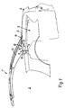
- adjustable vehicle roof 1 of a Cabriogenes is between the closed position shown, in a vehicle interior 2 is covered, and an open position, in which the vehicle roof 1 in a rear-side convertible top compartment 3 sunk, to adjust.
- the adjustable Vehicle roof 1 is a hardtop with two, if necessary also three coherent, in itself rigid roof parts, in the open or storage position in the top compartment 3 above the other to be stowed lying down.
- it may be the vehicle roof 1 and a Softtop with a hood frame and a top cloth held by the hood frame act.
- the top compartment 3 is located in the rear of the vehicle and adjoins the vehicle interior 2 at the rear, which is separated by a partition 4 from the rear area.
- the top compartment 3 is to be closed by a top compartment lid 5, which at the same time forms a trunk lid and around a rear, rear-side pivot axis 6 from that shown in Fig. 1 Closing or covering position in a the top compartment opening opening position is to pivot.
- the top compartment lid 5 can also be a second, the vehicle interior be adjacent pivot axis open to the Trunk from the rear of the vehicle to make accessible.
- the cover unit 7 is in two parts with a front, the vehicle interior adjacent cover member 8 and a rear cover part. 9 executed, wherein the rear cover 9 pivotally connected to the front cover 8 is connected and in the one shown in Fig. 1 Closed position of the vehicle roof in a position below the front cover is pivoted, creating a Passage 11 is released in the free space 10, through which a main link 12 may extend therethrough, which component the roof kinematics of the vehicle roof is.
- the passage 11 is located between the front edge of the top compartment lid 5 and the front cover 8.
- the front cover 8 is suitably pivotally connected to a roof part, in particular with the main link 12, and can be seen from the illustrated, about horizontal cover layer in a panned opening position be transferred to the passage 11 for the transfer the vehicle roof between closed and open position to enlarge.
- the joint over which the front cover 8 pivotally coupled to a vehicle or roof component, is provided with reference numeral 13 and is located on the vehicle interior 2 facing side in the front edge area of the Cover 8.
- the back Cover member 9 is about two joints 14 about a transverse axis Transversely to the vehicle longitudinal axis pivotally connected to the front cover 8 coupled and from the in Fig. 2 with a solid Dash shown, unfolded cover in the with to pivot the dotted line shown release position, in which the passage for the supporting roof component is released towards the top compartment and the rear cover - In this position marked with reference numerals 9 '- in a position below the front cover 8 is located.
- an actuator 15 For transferring the rear cover part 9 between its cover layer, in the front and rear cover 8 and 9 in lie on a common, approximately horizontal plane, and that the Passage releasing release position is an actuator 15 is provided, which in the embodiment, a train-pressure cable includes and kinematically in particular on the roof kinematics is forced, to a positive control of the relative movement the rear cover part 9 opposite the front cover part 8 depending on the vehicle roof position to achieve.
- the train-pressure cable of the actuator 15 is at the front Cover 8 attached via brackets 16 and 17.
- a Actuating movement of the train-pressure cable of the actuator 15 is via a lever 18 and a coupling rod 19 in a Pivoting movement of the rear cover part 9 relative to the front Cover 8 implemented.
- Via a spring element 20, for example a gas spring is the entire adjusting kinematics in the direction of the unfolded position of the rear cover 9 kraftbeetzschlagt.
- the front cover part 8 is metallic, in particular as a magnesium die-cast component, and against all adjacent ones Components electrically isolated, especially opposite the rear cover part 9 and the body-side components or the roof components to which the front cover 8 is held.
- the metallic version and the electrical insulation opposite adjacent components opens the possibility the front cover 8 as an antenna for a car radio to use.
- the electromagnetic received from the cover Radiation is transmitted via a transmission cable 21 from the cover 8 transferred to the car radio.
- the transmission cable 21 is appropriate to the executed as a train-pressure cable actuator 15 held and guided, but electrically isolated from this.
- brackets 16 and 17, over which the pull-push cable attached to the front cover 8 are electrically made insulating, as well as the joints 14 between front and rear cover 8 and 9, in particular electrically have insulating bushings through which the axle the respective joint is guided; the same applies to the only suggestively shown joints 13, over which the front Cover 8 pivotally mounted on a vehicle or roof component is held.
- a plastic diaphragm 22 which in covering the cover unit closes the gap between the cover parts 8 and 9, so that a continuous, uninterrupted storage space is formed.
- the aperture 22 extends into the side area the rear cover member 9. The aperture 22 can also assume an electrically insulating function.
- a Spaltabdeckteil 23 is provided in the side area in the transition between front and rear cover 8 and 9, which made of a flexible and electrically insulating material, especially made of rubber.
- the Spaltabdeckteil bridged partly in the side area, the gap between the front and rear cover 8 and 9 as well as the gap between the rear cover part 9 and laterally adjacent thereto components of the vehicle.
- Adjacent to the longitudinal central axis are two buffers each 24 both on the underside of the front cover 8 as well as on the underside of the rear cover part 9, which in cover position of the cover unit in the case of a high, on the cover unit from above acting load for a support opposite the sunk in the top compartment roof should provide.
- the buffers are also useful from a made of electrically insulating material.
- the actuator kinematics for transmitting the positioning movement from the actuator 15 to the rear cover 9 is a guideway 25 assigned, which directly on the bottom the front cover 8 is held and approximately part-circular is executed, wherein in the guide track 25 of the lever 28 of the actuating kinematics is performed.
- the guideway 25 is made especially plastic and ensures a reduced Friction during the movement of the reversing lever 18 along the Partial circular path in the adjustment of the rear cover part. 9 between folded and unfolded position.
- the guideway 25 may optionally also be designed as a backdrop his.
- FIG. 6 shows a fixing screw 29 used as an assembly aid on a bar 28 of the front cover 8.
- the fixing screw 29 is in the bar 28 on the underside of the cover unit attached.
Landscapes
- Engineering & Computer Science (AREA)
- Mechanical Engineering (AREA)
- Remote Sensing (AREA)
- Body Structure For Vehicles (AREA)
- Fittings On The Vehicle Exterior For Carrying Loads, And Devices For Holding Or Mounting Articles (AREA)
- Superstructure Of Vehicle (AREA)
- Vehicle Step Arrangements And Article Storage (AREA)
Description
- Fig. 1
- eine Seitenansicht auf ein verstellbares Fahrzeugdach in Schließposition, mit einem heckseitigen Verdeckkasten zur Aufnahme des Fahrzeugdaches in Öffnungsstellung, wobei ein Kofferraumdeckel als Verdeckkastendeckel sowie eine zweiteilige Abdeckeinheit als Hutablage dargestellt sind,
- Fig. 2
- eine Ansicht von unten auf die zweiteilige Abdeckeinheit,
- Fig. 3
- eine Darstellung gemäß Schnittlinie III-III aus Fig. 2,
- Fig. 4
- eine Darstellung gemäß Schnittlinie IV-IV aus Fig. 2,
- Fig. 5
- eine Darstellung gemäß Schnittlinie V-V aus Fig. 2,
- Fig. 6
- eine Darstellung gemäß Schnittlinie VI-VI aus Fig. 2.
Claims (14)
- Platte (5; 7) in einem Kraftfahrzeug, die zumindest abschnittsweise einen metallischen Tragkörper (8) aufweist und die an mindestens ein weiteres Bauteil (12) des Kraftfahrzeugs beweglich angekoppelt ist,
dadurch gekennzeichnet, dass der metallische Tragkörper (8) gegenüber den angrenzenden Bauteilen (9, 12) elektrisch isoliert ist. - Platte nach Anspruch 1,
dadurch gekennzeichnet, dass die Platte (5; 7) über ein Gelenk als Bestandteil einer Kinematik mit einem angrenzenden Bauteil gekoppelt ist. - Platte nach Anspruch 1 oder 2,
dadurch gekennzeichnet, dass an der Platte (5; 7) ein Stellantrieb angreift, der gegenüber dem metallischen Tragkörper elektrisch isoliert ist. - Platte nach einem der Ansprüche 1 bis 3,
dadurch gekennzeichnet, dass die Platte als Verdeckkastendeckel (5) ausgeführt ist, der zwischen einer einen Verdeckkasten (3) zur Aufnahme eines verstellbaren Fahrzeugdaches verschließenden Abdecklage und einer Öffnungslage zur Freigabe des Verdeckkastens (3) zu verstellen ist. - Platte nach einem der Ansprüche 1 bis 3,
dadurch gekennzeichnet, dass die Platte als verstellbare Abdeckeinheit (7) ausgeführt ist, mit der ein Freiraum (10) zwischen einem vorderen Randbereich eines Verdeckkastendeckels (5) zum Verschließen eines Verdeckkastens (3) und dem Fahrzeuginnenraum (2) abzudecken ist, wobei die Abdeckeinheit (7) über mindestens ein Gelenk (13) schwenkbar mit einem Fahrzeugbauteil gekoppelt und zumindest ein Teil der Abdeckeinheit (7) über einen Stellantrieb (15) zu verstellen ist. - Platte nach Anspruch 5,
dadurch gekennzeichnet, dass die Abdeckeinheit (7) über Gelenke (13) schwenkbar an einem verstellbaren Kinematikgestänge des Fahrzeugdaches (1) angelenkt ist. - Platte nach Anspruch 5 oder 6,
dadurch gekennzeichnet, dass die Abdeckeinheit (7) ein dem Fahrzeuginnenraum (2) zugewandtes vorderes Abdeckteil (8) und ein dem Fahrzeugheck benachbartes hinteres Abdeckteil (9) umfasst, das über Gelenke (14) schwenkbar mit dem vorderen Abdeckteil (8) gekoppelt ist. - Platte nach Anspruch 7,
dadurch gekennzeichnet, dass der Stellantrieb (15) am vorderen Abdeckteil (8) befestigt ist und bei einer Betätigung des Stellantriebs (15) das hintere Abdeckteil (9) gegenüber dem vorderen Abdeckteil (8) verschwenkt wird. - Platte nach Anspruch 7 oder 8,
dadurch gekennzeichnet, dass das vordere Abdeckteil (8) den metallischen Tragkörper bildet und gegenüber dem hinteren Abdeckteil (9) elektrisch isoliert ist. - Platte nach einem der Ansprüche 7 bis 9,
dadurch gekennzeichnet, dass zwischen vorderem und hinterem Abdeckteil (8, 9) eine Blende (22) angeordnet ist, die insbesondere aus Kunststoff besteht. - Platte nach einem der Ansprüche 5 bis 10,
dadurch gekennzeichnet, dass am Stellantrieb (15) ein mit dem metallischen Tragkörper verbundenes Übertragungskabel (21) geführt ist, welches gegenüber dem Stellantrieb (15) elektrisch isoliert ist. - Platte nach einem der Ansprüche 5 bis 11,
dadurch gekennzeichnet, dass der Stellantrieb (15) ein Zug-Druck-Kabel ist, welches über eine Kunststoffhalterung (16, 17) an der Abdeckeinheit (7) gehalten ist. - Platte nach einem der Ansprüche 5 bis 12,
dadurch gekennzeichnet, dass im Seitenbereich der Abdeckeinheit (7) ein flexibles, elektrisch isolierendes Spaltabdeckteil (23) an der Abdeckeinheit gehalten ist, das insbesondere aus Gummi besteht. - Platte nach einem der Ansprüche 1 bis 13,
dadurch gekennzeichnet, dass die Platte aus Magnesium besteht und insbesondere als Magnesium-Druckgussteil ausgeführt ist.
Applications Claiming Priority (3)
| Application Number | Priority Date | Filing Date | Title |
|---|---|---|---|
| DE10135223A DE10135223A1 (de) | 2001-07-24 | 2001-07-24 | Abdeckung für einen Verdeckkasten |
| DE10135223 | 2001-07-24 | ||
| PCT/EP2002/008081 WO2003010021A1 (de) | 2001-07-24 | 2002-07-19 | Platte in einem kraftfahrzeug mit einem metallischen tragkörper |
Publications (2)
| Publication Number | Publication Date |
|---|---|
| EP1315629A1 EP1315629A1 (de) | 2003-06-04 |
| EP1315629B1 true EP1315629B1 (de) | 2004-03-24 |
Family
ID=7692385
Family Applications (1)
| Application Number | Title | Priority Date | Filing Date |
|---|---|---|---|
| EP02764735A Expired - Lifetime EP1315629B1 (de) | 2001-07-24 | 2002-07-19 | Platte in einem kraftfahrzeug mit einem metallischen tragkörper |
Country Status (5)
| Country | Link |
|---|---|
| US (1) | US6840563B2 (de) |
| EP (1) | EP1315629B1 (de) |
| JP (1) | JP2004535328A (de) |
| DE (2) | DE10135223A1 (de) |
| WO (1) | WO2003010021A1 (de) |
Cited By (1)
| Publication number | Priority date | Publication date | Assignee | Title |
|---|---|---|---|---|
| DE102011012963B3 (de) * | 2011-03-04 | 2012-05-10 | Audi Ag | Antennenanordnung in einem Kraftfahrzeug |
Families Citing this family (5)
| Publication number | Priority date | Publication date | Assignee | Title |
|---|---|---|---|---|
| FR2839282B1 (fr) * | 2002-05-03 | 2005-04-22 | France Design | Systeme de plage arriere escamotable pour vehicule decouvrable a toit repliable |
| FR2851751B1 (fr) * | 2003-02-28 | 2006-06-23 | France Design | Systeme de plage arriere de vehicule |
| DE102004035231B4 (de) * | 2004-07-21 | 2006-10-26 | Audi Ag | Kraftfahrzeug mit einem Falt-Verdeck |
| DE102005057651B4 (de) * | 2005-12-01 | 2008-02-14 | Magna Car Top Systems Gmbh | Fahrzeug mit Abdeckanordnung |
| WO2014109732A1 (en) | 2013-01-08 | 2014-07-17 | Halliburton Energy Services, Inc. | Expandable screen completion tool |
Family Cites Families (20)
| Publication number | Priority date | Publication date | Assignee | Title |
|---|---|---|---|---|
| US2859441A (en) * | 1957-06-21 | 1958-11-04 | Rosenbaum Jacob | Automobile radio antenna |
| JPS4836583B1 (de) * | 1969-06-13 | 1973-11-06 | ||
| US4109251A (en) * | 1976-07-08 | 1978-08-22 | Macdougall James B | Adjustable antenna mounting bracket |
| FR2565417B1 (fr) * | 1984-05-29 | 1987-12-18 | Trt Telecom Radio Electr | Antenne formee a partir d'une cavite resonante comportant une face rayonnante |
| DE3685272D1 (de) * | 1985-06-28 | 1992-06-17 | Toyota Motor Co Ltd | Fahrzeugantennensystem. |
| JPH0638562B2 (ja) * | 1985-08-12 | 1994-05-18 | 日産自動車株式会社 | 車両用アンテナ |
| US4758166A (en) * | 1986-04-07 | 1988-07-19 | Ford Motor Company | Concealed radio antenna |
| US4866453A (en) * | 1988-08-15 | 1989-09-12 | General Motors Corporation | Vehicle slot antenna with parasitic slot |
| JPH05167327A (ja) * | 1991-12-12 | 1993-07-02 | Mazda Motor Corp | 車両用アンテナ装置 |
| US5402134A (en) * | 1993-03-01 | 1995-03-28 | R. A. Miller Industries, Inc. | Flat plate antenna module |
| DE4403643C2 (de) * | 1994-02-05 | 2003-04-10 | Fuba Automotive Gmbh | Antennenanordnung bei Kraftfahrzeugen |
| DE4446483C2 (de) * | 1994-12-23 | 1998-02-26 | Daimler Benz Ag | Hardtop-Fahrzeug |
| JPH10329615A (ja) * | 1997-06-03 | 1998-12-15 | Hitachi Chem Co Ltd | アンテナ内蔵自動車部品 |
| DE29818430U1 (de) * | 1998-10-15 | 1999-05-12 | Wilhelm Karmann GmbH, 49084 Osnabrück | Antenneneinheit |
| DE19928213C1 (de) * | 1999-06-19 | 2001-05-23 | Sihn Jr Kg Wilhelm | Schlitzantenne für Kraftfahrzeuge |
| DE10010226A1 (de) * | 1999-08-31 | 2001-03-01 | Lindenmeier Heinz | Antenne auf dem Fenster eines Kraftfahrzeugs |
| US6236373B1 (en) * | 1999-09-15 | 2001-05-22 | Humentech 21 Company | Vehicle sun visor with radio antenna |
| DE10025130A1 (de) * | 2000-05-20 | 2001-11-22 | Volkswagen Ag | Integration von Antennen in Karosseriebauteilen, diein Mischbauweise hergestellt sind |
| DE10050286B4 (de) * | 2000-10-10 | 2004-08-05 | Cts Fahrzeug-Dachsysteme Gmbh | Mehrteilige Abdeckung für Fahrzeuge |
| DE10110848A1 (de) * | 2001-03-07 | 2002-09-12 | Arvinmeritor Gmbh | Deckel für ein Schiebedach |
-
2001
- 2001-07-24 DE DE10135223A patent/DE10135223A1/de not_active Withdrawn
-
2002
- 2002-07-19 WO PCT/EP2002/008081 patent/WO2003010021A1/de not_active Ceased
- 2002-07-19 DE DE50200310T patent/DE50200310D1/de not_active Expired - Lifetime
- 2002-07-19 JP JP2003515393A patent/JP2004535328A/ja active Pending
- 2002-07-19 EP EP02764735A patent/EP1315629B1/de not_active Expired - Lifetime
-
2003
- 2003-06-09 US US10/456,626 patent/US6840563B2/en not_active Expired - Fee Related
Cited By (1)
| Publication number | Priority date | Publication date | Assignee | Title |
|---|---|---|---|---|
| DE102011012963B3 (de) * | 2011-03-04 | 2012-05-10 | Audi Ag | Antennenanordnung in einem Kraftfahrzeug |
Also Published As
| Publication number | Publication date |
|---|---|
| DE50200310D1 (de) | 2004-04-29 |
| US20030209920A1 (en) | 2003-11-13 |
| DE10135223A1 (de) | 2003-02-27 |
| US6840563B2 (en) | 2005-01-11 |
| JP2004535328A (ja) | 2004-11-25 |
| WO2003010021A1 (de) | 2003-02-06 |
| EP1315629A1 (de) | 2003-06-04 |
Similar Documents
| Publication | Publication Date | Title |
|---|---|---|
| EP1308333B1 (de) | Ablegbares Fahrzeugdach für ein Cabriolet | |
| EP1302351B1 (de) | Ablegbares Fahrzeugdach für ein Cabriolet | |
| DE19964029C1 (de) | Umwandelbares Fahrzeugdach | |
| EP1118489B1 (de) | Umwandelbares Fahrzeugdach | |
| DE10050286B4 (de) | Mehrteilige Abdeckung für Fahrzeuge | |
| EP1275543A2 (de) | Abdeckvorrichtung für einen Verdeckkasten | |
| DE19936252C5 (de) | Hardtop-Fahrzeugdach | |
| EP1565335B1 (de) | Kraftfahrzeug | |
| DE10234351B4 (de) | Cabriolet mit ablegbarem Klappdach | |
| WO2005095137A1 (de) | Faltverdeck für ein cabriolet-fahrzeug sowie cabriolet-fahrzeug mit einem faltverdeck | |
| DE10217915C5 (de) | Cabriolet-Fahrzeug mit zumindest einem starren rückwärtigen Dachabschluß | |
| EP1275544A1 (de) | Abdeckvorrichtung für einen Verdeckkasten | |
| DE10249299B4 (de) | Stauraumabdeckung eines Cabriolets | |
| WO2003010021A1 (de) | Platte in einem kraftfahrzeug mit einem metallischen tragkörper | |
| DE102005033599A1 (de) | Verstellvorrichtung eines Verdeckkastendeckels eines Cabriolets | |
| EP1198363B1 (de) | Zwischen einer schliessposition und einer öffnungsposition verstellbares hardtop-fahrzeugdach | |
| DE10242502B4 (de) | Verstellbares Fahrzeugdach | |
| WO2006066537A1 (de) | Cabriolet-fahrzeug mit einer beweglichen hutablage | |
| WO2007009445A1 (de) | Trägervorrichtung eines verdeckkastendeckels eines cabriolets | |
| DE10242501B4 (de) | Fahrzeugdach für ein Cabriolet-Fahrzeug | |
| DE202005008338U1 (de) | Antennenkonfiguration für den Rundfunkempfang in Kfz | |
| DE102005004531B4 (de) | Fahrzeug mit einem umwandelbaren Dach | |
| DE102004056121B4 (de) | Verdeck für ein Kraftfahrzeug | |
| EP1406778B1 (de) | Hardtop-fahrzeugdach mit mindestens einem starren dachteil | |
| DE10137465A1 (de) | Hardtop-Fahrzeugdach mit mindestens zwei starren Dachteilen |
Legal Events
| Date | Code | Title | Description |
|---|---|---|---|
| PUAI | Public reference made under article 153(3) epc to a published international application that has entered the european phase |
Free format text: ORIGINAL CODE: 0009012 |
|
| 17P | Request for examination filed |
Effective date: 20030318 |
|
| AK | Designated contracting states |
Designated state(s): AT BE BG CH CY CZ DE DK EE ES FI FR GB GR IE IT LI LU MC NL PT SE SK TR |
|
| 17Q | First examination report despatched |
Effective date: 20030513 |
|
| GRAP | Despatch of communication of intention to grant a patent |
Free format text: ORIGINAL CODE: EPIDOSNIGR1 |
|
| GRAS | Grant fee paid |
Free format text: ORIGINAL CODE: EPIDOSNIGR3 |
|
| GRAA | (expected) grant |
Free format text: ORIGINAL CODE: 0009210 |
|
| AK | Designated contracting states |
Kind code of ref document: B1 Designated state(s): DE FR GB IT |
|
| REG | Reference to a national code |
Ref country code: GB Ref legal event code: FG4D Free format text: NOT ENGLISH |
|
| REG | Reference to a national code |
Ref country code: IE Ref legal event code: FG4D Free format text: GERMAN |
|
| REF | Corresponds to: |
Ref document number: 50200310 Country of ref document: DE Date of ref document: 20040429 Kind code of ref document: P |
|
| GBT | Gb: translation of ep patent filed (gb section 77(6)(a)/1977) |
Effective date: 20040705 |
|
| REG | Reference to a national code |
Ref country code: IE Ref legal event code: FD4D |
|
| ET | Fr: translation filed | ||
| PLBE | No opposition filed within time limit |
Free format text: ORIGINAL CODE: 0009261 |
|
| STAA | Information on the status of an ep patent application or granted ep patent |
Free format text: STATUS: NO OPPOSITION FILED WITHIN TIME LIMIT |
|
| 26N | No opposition filed |
Effective date: 20041228 |
|
| PGFP | Annual fee paid to national office [announced via postgrant information from national office to epo] |
Ref country code: DE Payment date: 20100816 Year of fee payment: 9 Ref country code: FR Payment date: 20100802 Year of fee payment: 9 Ref country code: IT Payment date: 20100723 Year of fee payment: 9 |
|
| PGFP | Annual fee paid to national office [announced via postgrant information from national office to epo] |
Ref country code: GB Payment date: 20100721 Year of fee payment: 9 |
|
| GBPC | Gb: european patent ceased through non-payment of renewal fee |
Effective date: 20110719 |
|
| REG | Reference to a national code |
Ref country code: FR Ref legal event code: ST Effective date: 20120330 |
|
| PG25 | Lapsed in a contracting state [announced via postgrant information from national office to epo] |
Ref country code: FR Free format text: LAPSE BECAUSE OF NON-PAYMENT OF DUE FEES Effective date: 20110801 Ref country code: DE Free format text: LAPSE BECAUSE OF NON-PAYMENT OF DUE FEES Effective date: 20120201 |
|
| REG | Reference to a national code |
Ref country code: DE Ref legal event code: R119 Ref document number: 50200310 Country of ref document: DE Effective date: 20120201 |
|
| PG25 | Lapsed in a contracting state [announced via postgrant information from national office to epo] |
Ref country code: IT Free format text: LAPSE BECAUSE OF NON-PAYMENT OF DUE FEES Effective date: 20110719 |
|
| PG25 | Lapsed in a contracting state [announced via postgrant information from national office to epo] |
Ref country code: GB Free format text: LAPSE BECAUSE OF NON-PAYMENT OF DUE FEES Effective date: 20110719 |