EP1315566B1 - Vorrichtung zum schnellen thermischen recycling - Google Patents
Vorrichtung zum schnellen thermischen recycling Download PDFInfo
- Publication number
- EP1315566B1 EP1315566B1 EP00984534A EP00984534A EP1315566B1 EP 1315566 B1 EP1315566 B1 EP 1315566B1 EP 00984534 A EP00984534 A EP 00984534A EP 00984534 A EP00984534 A EP 00984534A EP 1315566 B1 EP1315566 B1 EP 1315566B1
- Authority
- EP
- European Patent Office
- Prior art keywords
- lid
- well
- plate
- pin
- wells
- Prior art date
- Legal status (The legal status is an assumption and is not a legal conclusion. Google has not performed a legal analysis and makes no representation as to the accuracy of the status listed.)
- Expired - Lifetime
Links
Images


Classifications
-
- B—PERFORMING OPERATIONS; TRANSPORTING
- B01—PHYSICAL OR CHEMICAL PROCESSES OR APPARATUS IN GENERAL
- B01L—CHEMICAL OR PHYSICAL LABORATORY APPARATUS FOR GENERAL USE
- B01L3/00—Containers or dishes for laboratory use, e.g. laboratory glassware; Droppers
- B01L3/50—Containers for the purpose of retaining a material to be analysed, e.g. test tubes
- B01L3/508—Containers for the purpose of retaining a material to be analysed, e.g. test tubes rigid containers not provided for above
- B01L3/5085—Containers for the purpose of retaining a material to be analysed, e.g. test tubes rigid containers not provided for above for multiple samples, e.g. microtitration plates
- B01L3/50851—Containers for the purpose of retaining a material to be analysed, e.g. test tubes rigid containers not provided for above for multiple samples, e.g. microtitration plates specially adapted for heating or cooling samples
-
- B—PERFORMING OPERATIONS; TRANSPORTING
- B01—PHYSICAL OR CHEMICAL PROCESSES OR APPARATUS IN GENERAL
- B01L—CHEMICAL OR PHYSICAL LABORATORY APPARATUS FOR GENERAL USE
- B01L3/00—Containers or dishes for laboratory use, e.g. laboratory glassware; Droppers
- B01L3/50—Containers for the purpose of retaining a material to be analysed, e.g. test tubes
- B01L3/508—Containers for the purpose of retaining a material to be analysed, e.g. test tubes rigid containers not provided for above
- B01L3/5085—Containers for the purpose of retaining a material to be analysed, e.g. test tubes rigid containers not provided for above for multiple samples, e.g. microtitration plates
- B01L3/50853—Containers for the purpose of retaining a material to be analysed, e.g. test tubes rigid containers not provided for above for multiple samples, e.g. microtitration plates with covers or lids
-
- B—PERFORMING OPERATIONS; TRANSPORTING
- B01—PHYSICAL OR CHEMICAL PROCESSES OR APPARATUS IN GENERAL
- B01L—CHEMICAL OR PHYSICAL LABORATORY APPARATUS FOR GENERAL USE
- B01L7/00—Heating or cooling apparatus; Heat insulating devices
- B01L7/52—Heating or cooling apparatus; Heat insulating devices with provision for submitting samples to a predetermined sequence of different temperatures, e.g. for treating nucleic acid samples
-
- G—PHYSICS
- G05—CONTROLLING; REGULATING
- G05D—SYSTEMS FOR CONTROLLING OR REGULATING NON-ELECTRIC VARIABLES
- G05D23/00—Control of temperature
- G05D23/01—Control of temperature without auxiliary power
- G05D23/13—Control of temperature without auxiliary power by varying the mixing ratio of two fluids having different temperatures
- G05D23/1393—Control of temperature without auxiliary power by varying the mixing ratio of two fluids having different temperatures characterised by the use of electric means
-
- G—PHYSICS
- G05—CONTROLLING; REGULATING
- G05D—SYSTEMS FOR CONTROLLING OR REGULATING NON-ELECTRIC VARIABLES
- G05D23/00—Control of temperature
- G05D23/19—Control of temperature characterised by the use of electric means
- G05D23/1919—Control of temperature characterised by the use of electric means characterised by the type of controller
-
- Y—GENERAL TAGGING OF NEW TECHNOLOGICAL DEVELOPMENTS; GENERAL TAGGING OF CROSS-SECTIONAL TECHNOLOGIES SPANNING OVER SEVERAL SECTIONS OF THE IPC; TECHNICAL SUBJECTS COVERED BY FORMER USPC CROSS-REFERENCE ART COLLECTIONS [XRACs] AND DIGESTS
- Y10—TECHNICAL SUBJECTS COVERED BY FORMER USPC
- Y10S—TECHNICAL SUBJECTS COVERED BY FORMER USPC CROSS-REFERENCE ART COLLECTIONS [XRACs] AND DIGESTS
- Y10S435/00—Chemistry: molecular biology and microbiology
- Y10S435/809—Incubators or racks or holders for culture plates or containers
Definitions
- This invention relates generally to a thermal cycling device and, more specifically, to an apparatus for the rapid heating and cooling of liquid samples.
- a thermal cycling device is an apparatus used to continuously change the temperature of a liquid sample.
- liquid refers to pure liquids, as well as liquids containing particulate matter (especially biological material) and solvents containing solute.
- Thermal cycling devices are well-known in the art and specific embodiments have been described in the scientific and patent literature. These devices fall into two general categories.
- the first category is a system based on the heating or cooling of a metal block typically either by moving a fluid through the block or by the addition of peltier heating directly to the block.
- a number of individual plastic tubes, a well plate (or a microliter plate which consists, essentially, of a number of plastic tubes connected together in a rectangular array) are used to hold the liquid samples.
- the plastic tubes are placed in the block and the temperature of the sample is regulated by changing the temperature of the metal block.
- the rate at which the temperature can be changed is limited by the relatively large thermal mass of the metal block. This being the case, the maximal rate of temperature change is relatively slow due to the fact that heat has to be added or removed from a relatively large thermal mass and this mass takes a significant time to reach thermal equilibrium.
- a second disadvantage of this category of thermal cyclers is that the liquid samples to be heated or cooled are "insulated" from the block by the plastic wall of the sample container (i.e., by the plastic tubes). Since plastic is a good insulator, not only must the heating and cooling source overcome the thermal mass of the metal block, but it must also overcome the insulating properties of the plastic sample container.
- sample containers currently in use for polymerase chain reaction (PCR) and Cycle Sequencing are either thin walled microfuge tubes, thin walled microwell plates - usually either 96-well or 384-well - or microcapillary tubes. All of these containers suffer from a common problem in that in all cases, the samples are heated or cooled from an external source and the heating and cooling system must overcome the insulating properties of the container.
- a related problem with these devices is that the plastic tubes are quite large in comparison to the liquid sample.
- the container volume ranges from 300 microliters ( ⁇ l) to 120 ⁇ l whereas the sample volume is usually only 5-25 ⁇ l.
- PCR polymerase chain reaction
- thermal cyclers that utilize a metal block for heating and cooling liquid samples. These include MJ Research, Techne, Lab Line, Thermolyne, Corbett Research, and Hybaid.
- the second type of thermal cycling device involves the use of microcapillary tubes that are placed in a chamber, and heating the chamber by forcing hot air or cold air into the chamber. This method is somewhat similar to heating the samples with a convection oven and cooling the samples with a refrigeration system.
- a current manufacturer of this type of thermal cycler is ldaho Technologies.
- This second type of thermal cycling device has the advantage that the thermal mass that needs to be heated is relatively small, i.e, the capillary tube, sample, and the interior of the chamber.
- this system has a number of limitations.
- Capillary tubes by their very nature are difficult to manipulate and are not suitable to robotic automation. That is, while a limited number of samples can be prepared in this fashion, it would be extremely difficult, if not impossible to process the number of samples per day (usually on the order of 100,000 that are usually necessary for a particular study).
- Microcapillaries as a container for PCR and Cycle Sequencing have an associated set of problems. First and foremost is the fact that these containers are not automation friendly. That is, it is difficult if not impossible for robotic liquid handlers to place liquid within a capillary. Consequently, the liquid handling is typically performed in a microfuge tube or microwell plate; then the capillary is brought into contact with the liquid and the liquid is drawn into the capillary by capillary action. This negates one of the presumed advantages of the capillary system in that a significantly larger volume of reagent must be prepared even though only a small portion of that reagent is used within the capillary. Another problem with capillaries is that they are difficult to seal.
- Each capillary typically has to be heat sealed to melt the glass capillary. Even if other types of materials are used for the capillaries, sealing is difficult and not amenable to automation. Finally, after the reaction has taken place, the capillary must be broken or cut and the reaction product removed. Since the sample is held within the capillary by capillary action, the removal of the sample is difficult at best.
- 1536-well plates are not conducive to the current methods of thermal cycling. There are several reasons for this. With a very high well density and a center to center spacing of 2.25 millimeters the inter-well distance is approximately 0.5 millimeters. This small distance makes it nearly impossible to surround each well with a heating/cooling unit as is currently done in 96-well or 384-well systems. Also, the plastic surface area to volume ratio is approximately 7-fold higher than in a 96-well plate or 384-well plate. With the increased plastic area, the insulating properties of the plastic that comprises the well is very difficult to overcome. Heating the plate from just the bottom is not practical since this causes temperature gradients within the well and consequently non-uniform heating.
- PCR and other methods have involved placing the samples in a small microtube and then placing the microtube in a water bath or heat block for temperature regulation.
- This method of controlling the temperature of the reaction has been successfully used on single tubes, 96-well plates, and 384-well plates.
- plastics typically act as excellent insulators so the external heating and cooling system has to overcome the insulating properties of the plastic before an effect on the solution is observed.
- An additional problem is that the solution volume is very small in comparison to the total well volume. Consequently, when the well is heated, the solution rends to evaporate and then condense on the cover of the well.
- the present invention can be divided into two embodiments.
- a device for heating and cooling a lid that is designed to fit over a well plate.
- this lid heating/cooling system There are two variations for this lid heating/cooling system.
- the mixed air Is directed via a series of ducts such that it heats or cools the surface of the lid in a uniform and highly controlled fashion.
- the second method is to bring a heating/cooling source, such as a Peltier device or heat/cold block in direct contact with the surface of the lid.
- a device in particular a well-plate containing, for example, 1536-wells with each well having a volume of approximately 6 ⁇ l, and a mating plate lid.
- the lid to this plate may have a copper clad surface and may contain a rubber seal on the other surface. Protruding through this lid is a series of "pins" that extend approximately from the rubber surface and which communicate with the copper clad surface for transferring heat from the lid.
- the device in the example related to the present invention heats or cools the copper clad surface and pins of the device in the present invention.
- the copper clad surface and pins rapidly transfers heat or removes heat from the pins.
- the pins in turn transfer heat or remove heat from the sample.
- the present invention describes a device whereby the wells of a 1536-well plate, for example, can be uniformly heated by applying a henting or cooling source directly into the well via the lid; the pins are in direct contact with the liquid sample(s) such that it can conduct heat into or out of the sample(s). In an example related to the present invention, the pins are near the liquid sample(s).
- the subject invention consists of a lid 10 that transmits heat to liquid samples 95 that are stored in a well-plate 99.
- a means for regulating the temperature of the lid 10 may be included with the heat-transmitting lid.
- the lid 10 must be able to conduct heat.
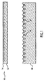
- the lid 10 is constructed from a circuit board type material, which gives the lid rigidity.
- a circuit board is typically made of a polymer base 12 and may have a copper clad layer 14 as illustrated in Figure 1.
- the clad layer may be any suitable metal and, preferably, is a material that conducts heat.
- the lid 10 is preferably adapted to be frictionally or matingly fitted over a well-plate 99.
- a means for heating and cooling the lid is applied to the lid 10.
- the close proximity of the lid 10 to the liquid samples 95 in the well-plate 99 controls the temperature of the liquid samples.
- This embodiment is the most basic embodiment in accordance with the present invention. If the lid has a cooper clad surface it is on the "top" side of the lid, away from the liquid samples. The cooper clad surface will distribute the heat more evenly over the lid 10 but is not crucial to this embodiment.
- the base 12 of the lid 10 has a copper clad upper or top layer 14.
- the copper clad layer 14 is useful in evenly distributing heat across the entire upper surface of the lid 10.
- the side opposite of the copper clad may be coated with a thin layer of silicone rubber 16 or a similar material.
- the silicone rubber coating 16 helps to seal the lid onto the well-plate 99 thereby inhibiting water loss (evaporation) of the solution during the repeated heating and cooling cycles.
- the lid 10 is designed to frictionally engage the well-plate 99, only a perimeter coating of silicone rubber or no silicone rubber may be needed.
- One or more pins 18 communicate with the copper clad surface of the lid 10 in order to transmit heat from the top of the lid along the length of the pins 18.
- a plurality of holes are drilled into the lid 10 on a dimensional array that corresponds to the dimensions of the well plate 99 that will be used. For example, for a 1536-well plate having a 32 by 48 array of wells, the holes would be drilled in a 32 by 48 array with a center to center spacing of 2.25 millimeters as illustrated in Figure 4. The 1536 pins 18 are then inserted through these holes such that they protrude beyond the silicone seal as illustrated in Figures 2A, 2B and 3. Based on the depth of a standard 1536- well plate, the pins will protrude approximately 3 mm from the bottom surface of the lid 10.
- each pin is in direct contact with the copper clad as illustrated in Figure 5.
- Knurls may be formed proximate the top of each pin 18.
- a head on each pin 18 may prevent it from sliding completely through the hole. It will be appreciated by those skilled in the art that other means for attaching the pins may be used, for example, soldering the top of each pin to the copper clad surface 14.
- the pins may or may not protrude from the side with the copper clad (i.e., the top side of the lid). If the pins do protrude above the copper clad surface of the lid, it should preferably not exceed 0.2 mm.
- the pins can be constructed from any material that is capable of conducting heat.
- the pins are constructed from tin/lead coated brass wire.
- Other materials such as aluminum, gold, copper, or other metals could be used along with certain ceramics and plastics.
- a portion of the pin 18 that extends from the bottom side of the lid is designed to make contact with the sample stored in the respective well. (see Figure 3). It would be obvious to one skilled in the art that the pin lengths and the amount of liquid sample may be adjusted to ensure that the pins are at least partially submerged in the liquid sample. Accordingly, as the temperature of the lid is changed, the temperature of the pins change, thereby directly heating or cooling the sample.
- An advantage of this system is the volume of the heating/cooling device, "pin", versus the volume of the sample.
- the heating/cooling device that is inserted directly into the sample has a volume of approximately 10% of the liquid volume.
- This comparatively large volume pin insures rapid temperature equilibrium in the sample.
- the pin 18 can be designed to maximize surface area such that heat transfer between the liquid sample and the pin is optimized. The larger the pin cross sectional area, the faster the heat transfer.
- the metal pins may need to be coated with a plastic or other inert material so that the metal will not interfere with the reaction that is to occur in the samples. If this is the case, the pins can be coated with gold, polypropylene, polystyrene, or other metals, plastics or ceramics that are biologically inert.
- the pins in the preferred embodiment are cylindrical in shape. However, rectangular, hexagonal, elliptical, star or other shaped rods could also be used.
- the tip of the pin that protrudes into the liquid can be concave or convex, have ridges or other structures that can trap small quantities of liquid.
- One advantage of this system is that after the PCR or cycle sequencing reaction is complete, the lid can be removed and used as a storage device for a small amount of the material in the well. If the reaction needs to be repeated the lid can be reused to generate a new sample by the small quantities of the samples attached to the pins.
- the lid 10 can also be used to place small amounts of sample onto other substrates.
- the pins can be heated either by row, column, or individually, simply by cutting the metal clad such that there are two or more separate areas that can be heated or cooled individually.
- the thermal cycler could be constructed in the form of a Peltier device such that the Peltier could be brought into direct contact with a row or column of pins.
- the lid 10 includes two or more plastic ears 90 that serve several purposes. First, these plastic pieces are used to position the lid on the plate such that the pins are inserted directly into the corresponding well. These plastic ears 90 also serve to protect the pins both from contamination and from potential damage as illustrated in Figure 6.
- the actual thermal mass that needs to be heated or cooled in this device is very small and includes the thin sheet of copper clad on the surface of the lid and the pin array. This low thermal mass allows the temperature of the system to be changed very rapidly and thermal equilibrium will be reached rapidly.
- the 1536-well plate is constructed based on the Proposed Society for Biomolecular Screening (SBS) standard plate configuration.
- the overall dimensions of the plate are: 85.48mm in width, 127.76mm in length, and 14.75mm in height.
- the well-to-well spacing on the 1536-well plate is 2.25mm center to center and on the 384-well plate is 4.5mm center to center.
- the plate meets the SBS standard in all aspects except for the positioning slots 80 illustrated in Figure 4 to accept the PCR lid. On both short sides of the plate, positioning slots are formed such that the lid 10 can be positioned directly upon the plate without the heating/cooling pins contacting the side walls of the wells.
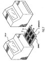
- FIG. 7 An automated device for positioning the lid over the well-plate by aligning the pins with its corresponding well is easily designed as illustrated in Figure 7. As long as the same rectangular array of pins that correspond to the rectangular array of wells is used, a lid 10 can be designed for use with any well-plate.
- the thermal cycler is designed to accept from one to six plates: the plates may have either 96, 384, or 1536 wells. When fully loaded with six 1536-well plates, the system can process >9000 samples at one time.
- the thermal cycler tray onto which the plates will be placed, contains an interlock system that positions each plate precisely in the cycler.
- This tray indexes out to the user and can be loaded either manually or robotically with plates as illustrated in Figure 7.
- a compression screen is brought down into contact with the lid. This compression screen applies a slight pressure to the lid 10 causing it to be compressed onto the plate 99. This action compresses the rubber seal 16 around each of the wells thus making each well air and liquid tight.
- Temperature control within the thermal cycler can be performed by the mixing of two air sources.
- the first, or “hot”, air source is produced passing air over a resistive heating coil to bring the air temperature up to >250°C.
- the second, or “cold”, air source is produced by passing air over a refrigeration unit cooling the air to 10°C.
- These two air sources are then mixed in the proper proportions in the vortex chamber to create air at the proper temperature.
- Air from the vortex chamber is then passed over the copper clad surface of the lids 10 in the sample chamber. This conditioned air then either heats or cools the copper clad surface 14 and copper pins 18 of the lid 10. As the pins heat or cool, heat is either added directly to the samples through the pins or removed directly from the samples through the pins and dissipated at the copper clad surface 14 of the lid 10.
- Temperature control can also be achieved by the application of a Peltier device directly to the copper clad surface of the lid.
- the heating/cooling system is incorporated directly into the clamping device such that when the lid is clamped onto the plate, the Peltier device is compressed onto the copper clad surface of the lid.
- the application of current to the Peltier device will then heat one surface of the Peltier device while cooling the other side. Reversing the current flow will reverse the hot and cold surfaces.
- the heat energy is transferred to the copper clad portion of the lid. Similar to the embodiment that uses air to regulate the temperature of the samples, the lid transmits its energy to the pins and eventually to the samples.
Landscapes
- Health & Medical Sciences (AREA)
- Chemical & Material Sciences (AREA)
- General Health & Medical Sciences (AREA)
- Chemical Kinetics & Catalysis (AREA)
- Clinical Laboratory Science (AREA)
- Engineering & Computer Science (AREA)
- Hematology (AREA)
- General Physics & Mathematics (AREA)
- Automation & Control Theory (AREA)
- Physics & Mathematics (AREA)
- Analytical Chemistry (AREA)
- Biochemistry (AREA)
- Molecular Biology (AREA)
- Life Sciences & Earth Sciences (AREA)
- Apparatus Associated With Microorganisms And Enzymes (AREA)
- Automatic Analysis And Handling Materials Therefor (AREA)
- Processing Of Solid Wastes (AREA)
- Heat Treatment Of Steel (AREA)
- Measuring Or Testing Involving Enzymes Or Micro-Organisms (AREA)
Claims (16)
- Vorrichtung zur Steuerung der Temperatur einer flüssigen Probe (95), die in mindestens einer Kavität einer Mikrotiterplatte (99) aufbewahrt ist, wobei die Vorrichtung Folgendes umfasst:einen Deckel (10), der aus einem wärmehaltenden Material hergestellt ist, wobei der Deckel so bemessen ist, dass er die Oberseite der Mikrotiterplatte bedeckt, und der Deckel einen wärmeleitenden Abschnitt (14) umfasst, der auf einer Seite des Deckels aufgetragen ist, die der Seite des Deckels gegenüberliegt, welche der Mikrotiterplatte zugewandt ist;mindestens einen wärmeleitenden Stift (18), der zur Kommunikation mit dem wärmeleitenden Abschnitt des Deckels angeordnet ist, wobei der mindestens eine Stift dafür ausgelegt ist, in die Kavität eingerührt zu werden, die Kavität jedoch nicht physikalisch zu berühren, und der Stift eine derartige Länge aufweist, dass er sich in die Kavität erstreckt, und so ausgelegt ist, dass er die flüssige Probe in der Kavität physikalisch berührt, so dass die Wärme von dem wärmeleitenden Abschnitt des Deckels auf den Stift und schließlich auf die flüssige Probe übertragen wird.
- Vorrichtung nach Anspruch 1, wobei der wärmeleitende Abschnitt des Deckels ein Metall umfasst.
- Vorrichtung nach Anspruch 2, wobei das Metall aus der Gruppe von Metallen ausgewählt wird, die Folgendes umfasst: Kupfer, Aluminium, Gold, Silber, Platin, Zinn, Blei oder eine Kombination davon.
- Vorrichtung nach Anspruch 1, die des Weiteren ein Mittel zum Erwärmen und Kühlen umfasst, das dafür ausgelegt ist, mit dem Deckel zu kommunizieren, um Wärme auf den Deckel zu übertragen.
- Vorrichtung nach Anspruch 4, die des Weiteren ein Mittel zum Regeln der Temperatur des Mittels zum Erwärmen und Kühlen umfasst, wodurch die Temperatur des Deckels geregelt wird.
- Vorrichtung nach Anspruch 1, wobei die Anzahl von Stiften der Anzahl von Kavitäten in der Mikrotiterplatte entspricht.
- Vorrichtung nach Anspruch 6, wobei der Deckel eine Mikrotiterplatte bedeckt, die ein Kavitätengitter von 32 Kavitäten mal 48 Kavitäten aufweist.
- Vorrichtung nach Anspruch 6, die des Weiteren eine Beschichtung umfasst, die auf den Stift aufgetragen ist und einer Reaktion mit der Lösung widersteht, wenn der Stift in Kontakt mit der Lösung angeordnet wird.
- Vorrichtung nach Anspruch 8, wobei die Beschichtung eine Art von Polymer ist.
- Vorrichtung nach Anspruch 6, wobei jeder Stift in Form eines Hohlrohrs hergestellt ist, so dass der Stift durch Kapillarwirkung eine kleine Menge Flüssigkeit halten kann.
- Vorrichtung nach Anspruch 1, wobei der Deckel eine Mikrotiterplatte mit einem Kavitätengitter von 16 Kavitäten mal 24 Kavitäten bedeckt.
- Vorrichtung nach Anspruch 1, wobei der Deckel eine Mikrotiterplatte mit einem Kavitätengitter von 8 Kavitäten mal 12 Kavitäten bedeckt.
- Vorrichtung nach Anspruch 1, wobei der wärmehaltende Abschnitt des Deckels aus der Gruppe von Materialien ausgewählt wird, die Folgendes umfasst: Keramik, Kunststoff, Graphit oder Halbleiter.
- Vorrichtung nach Anspruch 1, wobei der Deckel des Weiteren ein Mittel (16) zum Bilden einer luftdichten Dichtung zwischen dem Deckel und der Mikrotiterplatte umfasst.
- Vorrichtung, um eine flüssige Probe (95) einer thermischen Kreislaufführung zu unterziehen, wobei die Vorrichtung Folgendes umfasst:(a) eine Platte (99) mit mindestens einer Kavität zum Halten der Flüssigkeit;(b) eine Vorrichtung nach Anspruch 1;(c) ein Mittel zum Steuern der Temperatur des Deckels und der zugehörigen Stifte, wodurch die Temperatur der Flüssigkeit geregelt wird.
- Vorrichtung nach Anspruch 15, die des Weiteren eine Kupferplattierung auf der oberen Fläche des Deckels umfasst.
Applications Claiming Priority (3)
| Application Number | Priority Date | Filing Date | Title |
|---|---|---|---|
| US655021 | 1996-05-29 | ||
| US09/655,021 US6640891B1 (en) | 2000-09-05 | 2000-09-05 | Rapid thermal cycling device |
| PCT/US2000/041240 WO2002020161A1 (en) | 2000-09-05 | 2000-10-18 | Rapid thermal recycling device |
Publications (3)
| Publication Number | Publication Date |
|---|---|
| EP1315566A1 EP1315566A1 (de) | 2003-06-04 |
| EP1315566A4 EP1315566A4 (de) | 2004-03-31 |
| EP1315566B1 true EP1315566B1 (de) | 2006-07-05 |
Family
ID=24627174
Family Applications (1)
| Application Number | Title | Priority Date | Filing Date |
|---|---|---|---|
| EP00984534A Expired - Lifetime EP1315566B1 (de) | 2000-09-05 | 2000-10-18 | Vorrichtung zum schnellen thermischen recycling |
Country Status (6)
| Country | Link |
|---|---|
| US (1) | US6640891B1 (de) |
| EP (1) | EP1315566B1 (de) |
| AT (1) | ATE332190T1 (de) |
| AU (1) | AU2001221136A1 (de) |
| DE (1) | DE60029256T2 (de) |
| WO (1) | WO2002020161A1 (de) |
Families Citing this family (21)
| Publication number | Priority date | Publication date | Assignee | Title |
|---|---|---|---|---|
| US20020100582A1 (en) * | 2000-09-05 | 2002-08-01 | Oldenburg Kevin R. | Rapid thermal cycling device |
| GB0110449D0 (en) * | 2001-04-28 | 2001-06-20 | Genevac Ltd | Improvements in and relating to the heating of microtitre well plates in centrifugal evaporators |
| US7258839B2 (en) * | 2001-12-21 | 2007-08-21 | Cytonome, Inc. | Temperature controlled microfabricated two-pin liquid sample dispensing system |
| US7373968B2 (en) * | 2002-01-08 | 2008-05-20 | Kevin R. Oldenburg | Method and apparatus for manipulating an organic liquid sample |
| US6730883B2 (en) * | 2002-10-02 | 2004-05-04 | Stratagene | Flexible heating cover assembly for thermal cycling of samples of biological material |
| DE04752947T1 (de) | 2003-05-23 | 2006-11-16 | Bio-Rad Laboratories, Inc., Hercules | Lokalisierte temperaturregelung für raumanordnungen von reaktionsmedien |
| US20050232818A1 (en) * | 2003-09-19 | 2005-10-20 | Donald Sandell | Single sheet seal applicator and cartridge |
| US20060013984A1 (en) * | 2003-09-19 | 2006-01-19 | Donald Sandell | Film preparation for seal applicator |
| US20060011305A1 (en) * | 2003-09-19 | 2006-01-19 | Donald Sandell | Automated seal applicator |
| US20050226780A1 (en) * | 2003-09-19 | 2005-10-13 | Donald Sandell | Manual seal applicator |
| US7223949B2 (en) * | 2004-04-21 | 2007-05-29 | Beckman Coulter, Inc. | Analysis apparatus having improved temperature control unit |
| WO2006074233A2 (en) * | 2005-01-06 | 2006-07-13 | Applera Corporation | Polypeptides having nucleic acid binding activity and compositions and methods for nucleic acid amplification |
| US20070059713A1 (en) * | 2005-09-09 | 2007-03-15 | Lee Jun E | SSB-DNA polymerase fusion proteins |
| EP2040983A4 (de) * | 2006-06-26 | 2011-08-03 | Life Technologies Corp | Komprimierbare transparente dichtung für offene mikroplatten |
| ES2669870T3 (es) | 2010-07-22 | 2018-05-29 | Gencell Biosystems Limited | Células de líquido compuesto |
| WO2013082139A1 (en) * | 2011-11-28 | 2013-06-06 | Rui Zhang | Thermal cycling using phase changing fluids |
| GB2502585A (en) * | 2012-05-31 | 2013-12-04 | Stratec Biomedical Ag | Method and Device for Regulating the Temperature of a Sample |
| WO2014083435A2 (en) | 2012-11-27 | 2014-06-05 | Gencell Biosystems Ltd. | Handling liquid samples |
| WO2015120398A1 (en) * | 2014-02-10 | 2015-08-13 | Gencell Biosystems Limited | Composite liquid cell (clc) mediated nucleic acid library preparation device, and methods for using the same |
| EP3545105A4 (de) * | 2017-01-19 | 2020-09-23 | Yantai AusBio Laboratories Co., Ltd. | System, verfahren und probenträger zum testen |
| WO2022132946A1 (en) * | 2020-12-16 | 2022-06-23 | Thrive Bioscience, Inc. | Method and apparatus for preventing cell culture plate condensation in an imaging system |
Family Cites Families (42)
| Publication number | Priority date | Publication date | Assignee | Title |
|---|---|---|---|---|
| US1006767A (en) | 1910-01-19 | 1911-10-24 | Gen Electric | Electric hair-drier. |
| US1456005A (en) | 1922-07-24 | 1923-05-22 | Harris Jack | Incubator |
| US2379474A (en) | 1943-11-10 | 1945-07-03 | Bramson Maurice | Heating cabinet, incubator, and the like |
| US3616264A (en) | 1969-06-30 | 1971-10-26 | Beckman Instruments Inc | Temperature-controlled discrete sample analyzer |
| US4038055A (en) | 1975-10-10 | 1977-07-26 | Block Engineering, Inc. | Gas chromatograph for continuous operation with infrared spectrometer |
| HU171609B (hu) | 1975-12-30 | 1978-02-28 | Mueszeripari Muevek Lab | Apparatura dlja opredelenija nevraminidazy infljuehncii |
| IT1101295B (it) | 1978-11-22 | 1985-09-28 | Erba Strumentazione | Camera gas-cromatografica |
| US4420679A (en) | 1982-02-26 | 1983-12-13 | Delta Associates, Inc. | Gas chromatographic oven using symmetrical flow of preheated - premixed ambient air |
| US4468423A (en) | 1982-11-17 | 1984-08-28 | Arlie Hall | Insulating cell element and structures composed thereof |
| US4481405A (en) | 1983-04-27 | 1984-11-06 | Malick Franklin S | Cooking appliance |
| US4701415A (en) | 1984-03-02 | 1987-10-20 | Mallinckrodt, Inc. | Controlled atmosphere enclosure |
| JPS60241884A (ja) | 1984-05-15 | 1985-11-30 | Tokyo Daigaku | 自動サイクリング反応装置およびこれを用いる自動分析装置 |
| US4683195A (en) | 1986-01-30 | 1987-07-28 | Cetus Corporation | Process for amplifying, detecting, and/or-cloning nucleic acid sequences |
| US5038852A (en) | 1986-02-25 | 1991-08-13 | Cetus Corporation | Apparatus and method for performing automated amplification of nucleic acid sequences and assays using heating and cooling steps |
| US4683202A (en) | 1985-03-28 | 1987-07-28 | Cetus Corporation | Process for amplifying nucleic acid sequences |
| US5333675C1 (en) | 1986-02-25 | 2001-05-01 | Perkin Elmer Corp | Apparatus and method for performing automated amplification of nucleic acid sequences and assays using heating and cooling steps |
| US4965188A (en) | 1986-08-22 | 1990-10-23 | Cetus Corporation | Process for amplifying, detecting, and/or cloning nucleic acid sequences using a thermostable enzyme |
| US4889818A (en) | 1986-08-22 | 1989-12-26 | Cetus Corporation | Purified thermostable enzyme |
| US4902624A (en) | 1987-11-23 | 1990-02-20 | Eastman Kodak Company | Temperature cycling cuvette |
| US5354663A (en) * | 1988-05-04 | 1994-10-11 | Charm Sciences, Inc. | Microbial inhibition test kit and method |
| EP0342155A3 (de) | 1988-05-13 | 1990-06-27 | Agrogen-Stiftung | Laboratoriumsgerät zum wahlweisen Heizen und Kühlen |
| US4865986A (en) | 1988-10-06 | 1989-09-12 | Coy Corporation | Temperature control apparatus |
| US5236666A (en) | 1989-12-01 | 1993-08-17 | Akzo N.V. | Temperature regulation in a sample handling system for an optical monitoring system |
| US5455175A (en) | 1990-06-04 | 1995-10-03 | University Of Utah Research Foundation | Rapid thermal cycling device |
| KR100236506B1 (ko) | 1990-11-29 | 2000-01-15 | 퍼킨-엘머시터스인스트루먼츠 | 폴리머라제 연쇄 반응 수행 장치 |
| EP0542422A1 (de) * | 1991-11-12 | 1993-05-19 | General Atomics | Mikrotiterplatte mit mehreren Vertiefungen |
| FI915731A0 (fi) | 1991-12-05 | 1991-12-05 | Derek Henry Potter | Foerfarande och anordning foer reglering av temperaturen i ett flertal prov. |
| US5432086A (en) | 1992-11-18 | 1995-07-11 | Sy-Lab Vertriebsgellschaft M.B.H. | Apparatus for the automatic monitoring of microorganism culture |
| US5525300A (en) | 1993-10-20 | 1996-06-11 | Stratagene | Thermal cycler including a temperature gradient block |
| DE4435107C1 (de) | 1994-09-30 | 1996-04-04 | Biometra Biomedizinische Analy | Miniaturisierter Fluß-Thermocycler |
| US5721136A (en) | 1994-11-09 | 1998-02-24 | Mj Research, Inc. | Sealing device for thermal cycling vessels |
| BE1010984A3 (nl) | 1995-02-17 | 1999-03-02 | Praet Peter Van | Incubator voor microtiter plaat. |
| DE19519015C1 (de) | 1995-05-24 | 1996-09-05 | Inst Physikalische Hochtech Ev | Miniaturisierter Mehrkammer-Thermocycler |
| US5604130A (en) | 1995-05-31 | 1997-02-18 | Chiron Corporation | Releasable multiwell plate cover |
| DE19534632A1 (de) * | 1995-09-19 | 1997-03-20 | Boehringer Mannheim Gmbh | System zur Temperaturwechselbehandlung von Probenflüssigkeiten |
| US5863507A (en) | 1996-11-07 | 1999-01-26 | James; Lizymol | Benchtop cooler |
| EP0990142A4 (de) * | 1996-12-31 | 2000-09-27 | Genometrix Genomics Inc | Molekulares multiplexanalyse verfahren und vorrichtung dazu |
| CA2324208C (en) * | 1998-03-18 | 2009-06-30 | Massachusetts Institute Of Technology | Vascularized perfused microtissue/micro-organ arrays |
| US6159368A (en) * | 1998-10-29 | 2000-12-12 | The Perkin-Elmer Corporation | Multi-well microfiltration apparatus |
| DE19859586C1 (de) | 1998-12-22 | 2000-07-13 | Mwg Biotech Ag | Thermocyclervorrichtung |
| US6171850B1 (en) | 1999-03-08 | 2001-01-09 | Caliper Technologies Corp. | Integrated devices and systems for performing temperature controlled reactions and analyses |
| US6423536B1 (en) * | 1999-08-02 | 2002-07-23 | Molecular Dynamics, Inc. | Low volume chemical and biochemical reaction system |
-
2000
- 2000-09-05 US US09/655,021 patent/US6640891B1/en not_active Expired - Lifetime
- 2000-10-18 EP EP00984534A patent/EP1315566B1/de not_active Expired - Lifetime
- 2000-10-18 AT AT00984534T patent/ATE332190T1/de not_active IP Right Cessation
- 2000-10-18 AU AU2001221136A patent/AU2001221136A1/en not_active Abandoned
- 2000-10-18 DE DE60029256T patent/DE60029256T2/de not_active Expired - Lifetime
- 2000-10-18 WO PCT/US2000/041240 patent/WO2002020161A1/en active IP Right Grant
Also Published As
| Publication number | Publication date |
|---|---|
| EP1315566A4 (de) | 2004-03-31 |
| US6640891B1 (en) | 2003-11-04 |
| DE60029256T2 (de) | 2007-07-05 |
| AU2001221136A1 (en) | 2002-03-22 |
| DE60029256D1 (de) | 2006-08-17 |
| EP1315566A1 (de) | 2003-06-04 |
| WO2002020161A1 (en) | 2002-03-14 |
| ATE332190T1 (de) | 2006-07-15 |
Similar Documents
| Publication | Publication Date | Title |
|---|---|---|
| EP1315566B1 (de) | Vorrichtung zum schnellen thermischen recycling | |
| US7611674B2 (en) | Device for the carrying out of chemical or biological reactions | |
| US7727479B2 (en) | Device for the carrying out of chemical or biological reactions | |
| JP4550780B2 (ja) | 複数の容器を有する反応装置のための温度制御 | |
| US20080026483A1 (en) | Thermal-cycling devices and methods of using the same | |
| US20070184548A1 (en) | Device for carrying out chemical or biological reactions | |
| EP2898952B1 (de) | Vorrichtung zur Durchführung chemischer oder biologischer Reaktionen | |
| EP2076605B1 (de) | Kühlung in einem thermocycler mit heizrohren | |
| US5819842A (en) | Method and apparatus for temperature control of multiple samples | |
| US5496517A (en) | Laboratory workstation using thermal vaporization control | |
| JP2002010777A (ja) | 反応容器、反応装置および反応液の温度制御方法 | |
| JP2002542445A (ja) | 急速加熱ブロックヒートサイクラー | |
| JP2009507238A (ja) | サンプルプレートアセンブリおよび生体サンプルを処理する方法 | |
| JP4977138B2 (ja) | 最適化されたサンプルホルダ形状を有するサーマルサイクラー | |
| US8722394B2 (en) | Laboratory apparatus with an arrangement for the tempering of samples and method of tempering samples | |
| JP6903638B2 (ja) | 生物学的分析のためのシステム及び方法 | |
| US20020100582A1 (en) | Rapid thermal cycling device | |
| CN112827524A (zh) | 一种热循环装置 | |
| US7958736B2 (en) | Thermoelectric device and heat sink assembly with reduced edge heat loss | |
| JPH1189553A (ja) | インキュベータブロック | |
| CN218579970U (zh) | 一种热循环装置 | |
| EP3344394B1 (de) | Thermische isolierung von reaktionsstellen auf einem substrat | |
| US8871161B2 (en) | Thermo-conductive reaction plate holder | |
| EP1252931A1 (de) | Vorrichtung zur thermozyklischen Vervielfältigung von Nukleinsäuresequenzen | |
| CN117015440A (zh) | 用于热循环的设备和相关方法 |
Legal Events
| Date | Code | Title | Description |
|---|---|---|---|
| PUAI | Public reference made under article 153(3) epc to a published international application that has entered the european phase |
Free format text: ORIGINAL CODE: 0009012 |
|
| 17P | Request for examination filed |
Effective date: 20030310 |
|
| AK | Designated contracting states |
Designated state(s): AT BE CH CY DE DK ES FI FR GB GR IE IT LI LU MC NL PT SE |
|
| AX | Request for extension of the european patent |
Extension state: AL LT LV MK RO SI |
|
| A4 | Supplementary search report drawn up and despatched |
Effective date: 20040216 |
|
| RIC1 | Information provided on ipc code assigned before grant |
Ipc: 7B 01L 3/00 A Ipc: 7B 01L 7/00 B |
|
| 17Q | First examination report despatched |
Effective date: 20050401 |
|
| GRAP | Despatch of communication of intention to grant a patent |
Free format text: ORIGINAL CODE: EPIDOSNIGR1 |
|
| GRAS | Grant fee paid |
Free format text: ORIGINAL CODE: EPIDOSNIGR3 |
|
| GRAA | (expected) grant |
Free format text: ORIGINAL CODE: 0009210 |
|
| AK | Designated contracting states |
Kind code of ref document: B1 Designated state(s): AT BE CH CY DE DK ES FI FR GB GR IE IT LI LU MC NL PT SE |
|
| PG25 | Lapsed in a contracting state [announced via postgrant information from national office to epo] |
Ref country code: IT Free format text: LAPSE BECAUSE OF FAILURE TO SUBMIT A TRANSLATION OF THE DESCRIPTION OR TO PAY THE FEE WITHIN THE PRESCRIBED TIME-LIMIT;WARNING: LAPSES OF ITALIAN PATENTS WITH EFFECTIVE DATE BEFORE 2007 MAY HAVE OCCURRED AT ANY TIME BEFORE 2007. THE CORRECT EFFECTIVE DATE MAY BE DIFFERENT FROM THE ONE RECORDED. Effective date: 20060705 Ref country code: NL Free format text: LAPSE BECAUSE OF FAILURE TO SUBMIT A TRANSLATION OF THE DESCRIPTION OR TO PAY THE FEE WITHIN THE PRESCRIBED TIME-LIMIT Effective date: 20060705 Ref country code: BE Free format text: LAPSE BECAUSE OF FAILURE TO SUBMIT A TRANSLATION OF THE DESCRIPTION OR TO PAY THE FEE WITHIN THE PRESCRIBED TIME-LIMIT Effective date: 20060705 Ref country code: AT Free format text: LAPSE BECAUSE OF FAILURE TO SUBMIT A TRANSLATION OF THE DESCRIPTION OR TO PAY THE FEE WITHIN THE PRESCRIBED TIME-LIMIT Effective date: 20060705 Ref country code: FI Free format text: LAPSE BECAUSE OF FAILURE TO SUBMIT A TRANSLATION OF THE DESCRIPTION OR TO PAY THE FEE WITHIN THE PRESCRIBED TIME-LIMIT Effective date: 20060705 |
|
| REG | Reference to a national code |
Ref country code: GB Ref legal event code: FG4D |
|
| REG | Reference to a national code |
Ref country code: CH Ref legal event code: EP |
|
| REG | Reference to a national code |
Ref country code: IE Ref legal event code: FG4D |
|
| REF | Corresponds to: |
Ref document number: 60029256 Country of ref document: DE Date of ref document: 20060817 Kind code of ref document: P |
|
| PG25 | Lapsed in a contracting state [announced via postgrant information from national office to epo] |
Ref country code: DK Free format text: LAPSE BECAUSE OF FAILURE TO SUBMIT A TRANSLATION OF THE DESCRIPTION OR TO PAY THE FEE WITHIN THE PRESCRIBED TIME-LIMIT Effective date: 20061005 Ref country code: SE Free format text: LAPSE BECAUSE OF FAILURE TO SUBMIT A TRANSLATION OF THE DESCRIPTION OR TO PAY THE FEE WITHIN THE PRESCRIBED TIME-LIMIT Effective date: 20061005 |
|
| PG25 | Lapsed in a contracting state [announced via postgrant information from national office to epo] |
Ref country code: ES Free format text: LAPSE BECAUSE OF FAILURE TO SUBMIT A TRANSLATION OF THE DESCRIPTION OR TO PAY THE FEE WITHIN THE PRESCRIBED TIME-LIMIT Effective date: 20061016 |
|
| PG25 | Lapsed in a contracting state [announced via postgrant information from national office to epo] |
Ref country code: IE Free format text: LAPSE BECAUSE OF NON-PAYMENT OF DUE FEES Effective date: 20061018 |
|
| PG25 | Lapsed in a contracting state [announced via postgrant information from national office to epo] |
Ref country code: MC Free format text: LAPSE BECAUSE OF NON-PAYMENT OF DUE FEES Effective date: 20061031 |
|
| NLV1 | Nl: lapsed or annulled due to failure to fulfill the requirements of art. 29p and 29m of the patents act | ||
| PG25 | Lapsed in a contracting state [announced via postgrant information from national office to epo] |
Ref country code: PT Free format text: LAPSE BECAUSE OF FAILURE TO SUBMIT A TRANSLATION OF THE DESCRIPTION OR TO PAY THE FEE WITHIN THE PRESCRIBED TIME-LIMIT Effective date: 20061205 |
|
| ET | Fr: translation filed | ||
| PLBE | No opposition filed within time limit |
Free format text: ORIGINAL CODE: 0009261 |
|
| STAA | Information on the status of an ep patent application or granted ep patent |
Free format text: STATUS: NO OPPOSITION FILED WITHIN TIME LIMIT |
|
| 26N | No opposition filed |
Effective date: 20070410 |
|
| REG | Reference to a national code |
Ref country code: CH Ref legal event code: NV Representative=s name: BOVARD AG PATENTANWAELTE |
|
| PG25 | Lapsed in a contracting state [announced via postgrant information from national office to epo] |
Ref country code: GR Free format text: LAPSE BECAUSE OF FAILURE TO SUBMIT A TRANSLATION OF THE DESCRIPTION OR TO PAY THE FEE WITHIN THE PRESCRIBED TIME-LIMIT Effective date: 20061006 |
|
| PG25 | Lapsed in a contracting state [announced via postgrant information from national office to epo] |
Ref country code: LU Free format text: LAPSE BECAUSE OF NON-PAYMENT OF DUE FEES Effective date: 20061018 |
|
| PG25 | Lapsed in a contracting state [announced via postgrant information from national office to epo] |
Ref country code: CY Free format text: LAPSE BECAUSE OF FAILURE TO SUBMIT A TRANSLATION OF THE DESCRIPTION OR TO PAY THE FEE WITHIN THE PRESCRIBED TIME-LIMIT Effective date: 20060705 |
|
| REG | Reference to a national code |
Ref country code: CH Ref legal event code: PFA Owner name: OLDENBURG, KEVIN R. Free format text: OLDENBURG, KEVIN R.#665 RIVERPOINT BOULEVARD#SPOKANE, WASHINGTON 99202 (US) -TRANSFER TO- OLDENBURG, KEVIN R.#665 RIVERPOINT BOULEVARD#SPOKANE, WASHINGTON 99202 (US) |
|
| REG | Reference to a national code |
Ref country code: DE Ref legal event code: R082 Ref document number: 60029256 Country of ref document: DE Representative=s name: GRUENECKER, KINKELDEY, STOCKMAIR & SCHWANHAEUS, DE |
|
| REG | Reference to a national code |
Ref country code: GB Ref legal event code: 732E Free format text: REGISTERED BETWEEN 20141113 AND 20141119 |
|
| REG | Reference to a national code |
Ref country code: GB Ref legal event code: 732E Free format text: REGISTERED BETWEEN 20141127 AND 20141203 |
|
| REG | Reference to a national code |
Ref country code: DE Ref legal event code: R082 Ref document number: 60029256 Country of ref document: DE Representative=s name: GRUENECKER, KINKELDEY, STOCKMAIR & SCHWANHAEUS, DE Effective date: 20141209 Ref country code: DE Ref legal event code: R081 Ref document number: 60029256 Country of ref document: DE Owner name: BROOKS AUTOMATION, INC., CHELMSFORD, US Free format text: FORMER OWNER: OLDENBURG, KEVIN R., SPOKANE, WASH., US Effective date: 20141209 Ref country code: CH Ref legal event code: PUE Owner name: BROOKS AUTOMATION, INC., US Free format text: FORMER OWNER: OLDENBURG, KEVIN R., US Ref country code: DE Ref legal event code: R082 Ref document number: 60029256 Country of ref document: DE Representative=s name: GRUENECKER PATENT- UND RECHTSANWAELTE PARTG MB, DE Effective date: 20141209 |
|
| REG | Reference to a national code |
Ref country code: FR Ref legal event code: TP Owner name: BROOKS AUTOMATION, INC., US Effective date: 20150729 |
|
| REG | Reference to a national code |
Ref country code: FR Ref legal event code: PLFP Year of fee payment: 16 |
|
| REG | Reference to a national code |
Ref country code: FR Ref legal event code: PLFP Year of fee payment: 17 |
|
| REG | Reference to a national code |
Ref country code: FR Ref legal event code: PLFP Year of fee payment: 18 |
|
| REG | Reference to a national code |
Ref country code: FR Ref legal event code: PLFP Year of fee payment: 19 |
|
| PGFP | Annual fee paid to national office [announced via postgrant information from national office to epo] |
Ref country code: FR Payment date: 20190919 Year of fee payment: 20 |
|
| PGFP | Annual fee paid to national office [announced via postgrant information from national office to epo] |
Ref country code: GB Payment date: 20190923 Year of fee payment: 20 |
|
| PGFP | Annual fee paid to national office [announced via postgrant information from national office to epo] |
Ref country code: CH Payment date: 20190923 Year of fee payment: 20 Ref country code: DE Payment date: 20190918 Year of fee payment: 20 |
|
| REG | Reference to a national code |
Ref country code: DE Ref legal event code: R071 Ref document number: 60029256 Country of ref document: DE |
|
| REG | Reference to a national code |
Ref country code: CH Ref legal event code: PL |
|
| REG | Reference to a national code |
Ref country code: GB Ref legal event code: PE20 Expiry date: 20201017 |
|
| PG25 | Lapsed in a contracting state [announced via postgrant information from national office to epo] |
Ref country code: GB Free format text: LAPSE BECAUSE OF EXPIRATION OF PROTECTION Effective date: 20201017 |