EP1314921A2 - Rohrbruchventil - Google Patents
Rohrbruchventil Download PDFInfo
- Publication number
- EP1314921A2 EP1314921A2 EP02026080A EP02026080A EP1314921A2 EP 1314921 A2 EP1314921 A2 EP 1314921A2 EP 02026080 A EP02026080 A EP 02026080A EP 02026080 A EP02026080 A EP 02026080A EP 1314921 A2 EP1314921 A2 EP 1314921A2
- Authority
- EP
- European Patent Office
- Prior art keywords
- spring
- insert body
- pipe rupture
- valve according
- housing
- Prior art date
- Legal status (The legal status is an assumption and is not a legal conclusion. Google has not performed a legal analysis and makes no representation as to the accuracy of the status listed.)
- Granted
Links
- 238000007789 sealing Methods 0.000 claims abstract description 19
- 230000002093 peripheral effect Effects 0.000 claims abstract description 11
- 239000011324 bead Substances 0.000 claims description 8
- 239000002184 metal Substances 0.000 claims description 8
- 230000015572 biosynthetic process Effects 0.000 claims description 6
- 238000007906 compression Methods 0.000 claims description 4
- 230000006835 compression Effects 0.000 claims description 4
- 238000002347 injection Methods 0.000 claims description 4
- 239000007924 injection Substances 0.000 claims description 4
- 239000004033 plastic Substances 0.000 claims description 4
- 238000011161 development Methods 0.000 claims description 3
- 239000013013 elastic material Substances 0.000 claims description 3
- 238000005520 cutting process Methods 0.000 claims description 2
- 238000004080 punching Methods 0.000 claims description 2
- 230000009467 reduction Effects 0.000 claims description 2
- 230000000284 resting effect Effects 0.000 claims 1
- 230000003213 activating effect Effects 0.000 abstract 1
- 238000013461 design Methods 0.000 description 7
- 238000004519 manufacturing process Methods 0.000 description 4
- 238000013459 approach Methods 0.000 description 3
- 239000012530 fluid Substances 0.000 description 3
- 238000000034 method Methods 0.000 description 3
- 230000004048 modification Effects 0.000 description 3
- 238000012986 modification Methods 0.000 description 3
- 230000004044 response Effects 0.000 description 3
- 239000006096 absorbing agent Substances 0.000 description 2
- 230000009471 action Effects 0.000 description 2
- 238000005452 bending Methods 0.000 description 2
- 230000008901 benefit Effects 0.000 description 2
- 230000000694 effects Effects 0.000 description 2
- 239000000463 material Substances 0.000 description 2
- 230000008569 process Effects 0.000 description 2
- 238000012545 processing Methods 0.000 description 2
- 230000035939 shock Effects 0.000 description 2
- 239000007787 solid Substances 0.000 description 2
- 238000012549 training Methods 0.000 description 2
- 238000011144 upstream manufacturing Methods 0.000 description 2
- 229910000760 Hardened steel Inorganic materials 0.000 description 1
- 238000010276 construction Methods 0.000 description 1
- 230000002950 deficient Effects 0.000 description 1
- 238000010586 diagram Methods 0.000 description 1
- 230000002349 favourable effect Effects 0.000 description 1
- 210000003746 feather Anatomy 0.000 description 1
- 238000009472 formulation Methods 0.000 description 1
- 239000000203 mixture Substances 0.000 description 1
- 230000036316 preload Effects 0.000 description 1
- 230000000750 progressive effect Effects 0.000 description 1
- 239000000243 solution Substances 0.000 description 1
- 230000001960 triggered effect Effects 0.000 description 1
Images


Classifications
-
- F—MECHANICAL ENGINEERING; LIGHTING; HEATING; WEAPONS; BLASTING
- F16—ENGINEERING ELEMENTS AND UNITS; GENERAL MEASURES FOR PRODUCING AND MAINTAINING EFFECTIVE FUNCTIONING OF MACHINES OR INSTALLATIONS; THERMAL INSULATION IN GENERAL
- F16L—PIPES; JOINTS OR FITTINGS FOR PIPES; SUPPORTS FOR PIPES, CABLES OR PROTECTIVE TUBING; MEANS FOR THERMAL INSULATION IN GENERAL
- F16L55/00—Devices or appurtenances for use in, or in connection with, pipes or pipe systems
- F16L55/10—Means for stopping flow in pipes or hoses
- F16L55/1022—Fluid cut-off devices automatically actuated
-
- F—MECHANICAL ENGINEERING; LIGHTING; HEATING; WEAPONS; BLASTING
- F16—ENGINEERING ELEMENTS AND UNITS; GENERAL MEASURES FOR PRODUCING AND MAINTAINING EFFECTIVE FUNCTIONING OF MACHINES OR INSTALLATIONS; THERMAL INSULATION IN GENERAL
- F16K—VALVES; TAPS; COCKS; ACTUATING-FLOATS; DEVICES FOR VENTING OR AERATING
- F16K17/00—Safety valves; Equalising valves, e.g. pressure relief valves
- F16K17/20—Excess-flow valves
- F16K17/22—Excess-flow valves actuated by the difference of pressure between two places in the flow line
- F16K17/24—Excess-flow valves actuated by the difference of pressure between two places in the flow line acting directly on the cutting-off member
- F16K17/28—Excess-flow valves actuated by the difference of pressure between two places in the flow line acting directly on the cutting-off member operating in one direction only
- F16K17/30—Excess-flow valves actuated by the difference of pressure between two places in the flow line acting directly on the cutting-off member operating in one direction only spring-loaded
Definitions
- valve which functions as a check valve, consists in particular in the occurrence of dangerous conditions in hydraulic systems, such as hydraulically operated piston-cylinder devices, for example in Avoid lifting platforms or in gripper and transport arms. If in one of the hydraulic line upstream line a break or a larger one Leakage occurs, there is a sudden drop in the working pressure of the Pressure medium. Triggered by this pressure drop, the pipe rupture valve responds, by closing and thereby causing the fluid to flow back into the defective line and prevented through the fracture into the environment. In the valve downstream sections of the existing pressure can largely are maintained, for example, an extended lift or a raised gripper arm remains in position almost unchanged.
- the insert body is as per the mentioned British patent as preferably made of plastic bush-like Solid body constructed and includes the spring coil.
- the Insert body In cross section is the Insert body, however, designed in the form of a gearwheel, with on its periphery circular tooth gaps are formed, the flow passages with the housing inner wall form for the pressure medium.
- the insert body is in one paragraph of the housing interior held by a snap ring with axial play.
- the shaft is made in one piece and on the outside of the valve plate with an adjustable Provide lock nut.
- the present invention has for its object a pipe break valve of the beginning to create the type mentioned, which is easy to assemble and Operational and functional safety, especially with the highest sealing effect characterized by a simpler and less expensive production method, i.e. through that the aforementioned problems are eliminated or at least reduced to a minimum can.
- a pipe rupture valve of the type mentioned at the beginning in which the insert body is formed as a sheet metal part. It can be a stamped and bent part or a particularly simple one Stamping process shaped, flat disc part.
- the insert body it is first possible on the one hand to significantly reduce the manufacturing effort of the insert body by this preferably as a stamped or bent-stamped part - or what the Alternative design relates, also as an injection molded part made of plastic or metal - can be manufactured; on the other hand, the pipe rupture valve according to the invention is also can be assembled with less effort, since the invention easily equips the Insert body with locking means enables the formation of a non-positive and positive Connection, in particular clipping the insert body with corresponding ones Fasteners of the wall of the housing interior, allow.
- the spring in the open position preloaded valve disc, the stem with its one-ended head and with the otherwise arranged securing element and the insert body and if necessary, the plate spring described below a pre-assembled Form unit.
- This pre-assembled unit can be more advantageous Embodiment have an insert sleeve, which in the outer peripheral region between the insert body and the valve plate is arranged and also with the Has valve plate interacting sealing seat.
- the insert sleeve has holding means for holding it within the housing on its outer circumference.
- This Execution has the advantage of a particularly simple assembly by simple Insert the pre-assembled module into the housing.
- the Assembly finished with regard to the valve opening stroke and the closing behavior be preset, because of the integrated valve sealing seat advantageously independent of housing tolerances.
- the insert body can be a circular, Breakthrough disc be formed, the outer, in the interior of the housing attachable holding part and preferably a substantially Guide stub protruding perpendicularly from the disk plane can, which forms the hollow cylindrical guide member for the spring.
- a Insert body can essentially axially on a shoulder of the housing interior be held free of play by a snap ring, which is the locking means for the insert body forms.
- the insert body is designed as a simple (flat) perforated disc, can with advantage a corresponding hollow cylindrical guide part also as the approach of Valve plates are formed.
- the insert body may have a basket with arms is formed, which with an elastically expandable or compressible in diameter Edge bead the outer holding part which can be fastened in the interior of the housing forms and on which a longitudinally extending guide socket is formed, which forms the hollow cylindrical guide part for the spring, the Basket an annular, interrupted by slits bottom area for planting the Has spring.
- the locking means for the Insert body preferably by said slit edge bead Insert body be formed. This can advantageously be an additional snap ring omitted.
- a counter spring it is achieved that in the "normal", spring-related Open position of the valve, the valve flow cross-section when the pressure rises Fluid by moving the valve plate against the force of the Opposing fields can still be enlarged.
- the counter spring can be a plate spring made of metal or a suitable one Plastic or as a particularly ring-shaped body made of a rubber-elastic Material (so-called rubber spring) should be formed.
- the pipe rupture valve can also be designed in this way be that in the closed position there is a slight flow of the pressure medium allows. This is made constructive by (at least) one throttle channel of the valve disk reached. This configuration consequently results in a downstream of the valve Line section the pressure slowly, throttled, so that a Slowly move the connected unit to a rest position, e.g. B. lower can. This is important for forklift trucks, for example, to lift a load slowly lower.
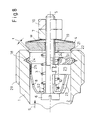
- an according to the invention in particular adjustable, pipe rupture valve for closing a pressure medium line in the event of damage the following parts: a housing 1, which has a substantially cylindrical Has interior 2, one of a spring 3, in particular one Coil spring, in an open position biased valve plate 4 to close the Interior 2, a one-piece shaft 5, the one end a head 6 and at the other end, at least one acting on the outside of the valve plate 4 Has securing element 7, and a flow passages arranged in the interior 2 8 for the pressure medium having insert body 9.
- the valve disk 4 and the insert body 9 are penetrated centrally by the shaft 5, for which purpose Corresponding bores or through openings, not specified available.
- the head 6 is designed in particular as an adjusting head in the form of a slotted screw and can cooperate with the fuse element 7 such that the bias the spring 3 by relative rotation of the adjustment head and / or the Securing element 7 is changeable.
- the securing element 7 is in particular a positionally lockable mother.
- the mother's position is advantageously secured using a Lock nut 10; for this purpose, however, there could also be one instead of the mother Lock nut or any other locking element 7 are used, especially when the valve is not with the preferred function of the Adjustability should be equipped.
- the insert body 9 is designed according to the invention as a sheet metal part, for which purpose FIG. 4 and 5 for the first embodiment (and in particular FIGS. 12 and 15 for the others Versions) for further details.
- the insert body 9 designed as a bent-stamped part, namely as an annular, openings having disc 11 to which a substantially perpendicular from the Shaped guide sleeve 12 protruding for the coil spring 3 is formed is.
- the disc 11 forms an outer, attachable in the interior 2 of the housing 1 Holding part of the insert body 9, while the guide socket 12 is a hollow cylindrical Guide part for the spring 3 forms. When installed, the coil spring overlaps the guide socket 12 and is on one side on the disc 11. It is different Spring 3 on the inside of the valve plate 4.
- the openings in the disk 11 form the flow passages 8 for the pressure medium.
- the insert body 9 has an outer, closed annular edge region 13 on.
- the flow passages adjoining it radially inwards 8 are preferably approximately trapezoidal.
- the annular edge area 13 (for attachment to the housing 1) is with an inner Ring area 14 (for supporting the spring 3) over, for example, six spoke-like Bridges 15 connected.
- the guide connector 12 can, for example, advantageously by a Flare the inner ring portion 14 be made.
- FIG. 1 and 2 are in the Valve locking means according to the invention to form a releasable force and / or positive connection of the insert body 9 with corresponding Fasteners of the wall of the housing interior 2 are available.
- the insert body 9 is in the installed state on a shoulder 16 of the housing interior 2 held in particular in the axial direction without play by a snap ring 17, which forms the locking means for the insert body 9.
- the corresponding ones Fasteners of the wall of the housing interior 2 are through an inner groove 18 formed in the wall.
- FIGS. 2 and 3 Pipe rupture valve differs from the basic version (Fig. 1) in that that between the outside of the valve plate 4 and the lockable nut 7, a counter spring 19 designed here as an example as a plate spring is arranged.
- a counter spring 19 designed here as an example as a plate spring is arranged.
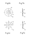
- FIGS. 6a, 6b, 6c - in each case a top view, 7a, 7b, 7c can be seen in each case sectional view
- the counter spring 19 is in Installed state arranged so that they serve the bias Counteracts spring 3, i.e. that in the case of the plate spring, its curvature W on the Securing element 7 is directed.
- the counter spring 19 achieves that in the open position of the valve increases the valve cross section when the pressure of the fluid increases can be.
- the enlargement of the flow cross section is over a Enlargement of the stroke t of the valve plate 4 set (Fig. 3).
- the valve plate 4 in a closed position with a particular conical peripheral edge 21 on a corresponding sealing seat 22 of the housing 1 is present.
- the sealing seat 22 is formed as an inner cone surface.
- FIG. 13 The operation of a valve according to the invention with a counter spring 19 is shown by Figure 13 illustrates.
- the diagram shows the dependence of the stroke t des Valve plates 4 from the pressure p of the pressure medium in the normal operating state, i.e. when the pressure medium in the in Fig. 1 to 3 (and Fig. 8) designated by the reference symbol S.
- Flow direction flows.
- the stroke t remains in a first pressure range A. of the valve plate 4 with increasing pressure p to a certain preset value H1 constant.
- the size and dynamics of the occurring Stroke increase Dt is determined by the spring characteristic of the counter spring 19.
- the Spring characteristic can be a linear characteristic (full line) or a non-linear characteristic (dash-dotted line: positive degressive increase, dashed line: positive progressive Increase).
- the counter spring 19 can preferably (corresponding to one desired stroke enlargement Dt) a stroke in the range of 0.1 to 5 mm, preferably have of 0.5 mm.
- FIG. 14 which illustrates the operation of the valve in the event of a damage event, one upstream of the valve according to the invention Serves pressure medium line, shows the dependence of the opening width t of the valve from the pressure "-p" of the pressure medium.
- the negative sign is due to that in the event of damage, the pressure medium has the tendency, contrary to that in the 1 to 3 (and Fig. 8) designated by the reference symbol S. Flow direction to flow, and that the pressure thus acts in the direction "-S".
- the Representation in FIG. 14 is characteristic of all the embodiments described of the pipe rupture valve according to the invention.
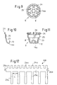
- the insert body 9 is as a basket having arms 23 (in particular spring-elastic arms) is formed, to which in turn a guide stub running in the longitudinal direction of the housing 1 12 is formed for the coil spring.
- the basket forms that outer, in the interior 2 of the housing 1 attachable holding part and Guide stub 12 in turn the hollow cylindrical guide part (- also as Holding part could be called -) for the spring 3.
- the locking means for the insert body 9 are in the second embodiment of the invention Valve through a (radially elastic compressible or expandable) Edge bead 24 of the insert body 9 having slots S1 is formed.
- the corresponding ones Fasteners of the wall of the housing interior 2 are - like in the first embodiment - by an inner groove 18 in the wall of the housing 1 educated.
- a snap ring 17 and a shoulder 16 for engaging the insert body 9 can omitted.
- the wall of the housing interior 2 thus faces in the area between the Adjustment head 6 of the stem 5 and the inside of the valve plate 4 (in a position in which is when the valve is in the closed state) only one two-stage diameter formation - a basic diameter that is about Corresponds to the outer diameter of the insert body 9, and a diameter of (Ring) inner groove 18, which is adapted to the outer diameter of the bead 24. (In contrast, in the first version there is a three-stage diameter formation in front.)
- the insert body 9 in be manufactured in a technically simple manner as a bent-stamped part
- the Development AW the flaps 23a corresponding to the basket arms 23, the slotted ones Edge bead 24 corresponding tabs 24a and a circumferential annular Connection section 25 shows corresponding web 25a.
- closure 26 in FIG. 11 To form a closed annular connecting portion 25 (closure 26 in FIG. 11) from this web 25a are non-positively and / or positively at the web ends interacting closure means (tab 26a, recess 26b) arranged or trained.
- Both the guide socket 12 (slotted in this embodiment) and a annular bottom region 14a, but interrupted by slots S2, for contact the spring 3, the inner ring portion 14 of the disc 11 at the first Execution corresponds, are also from the tabs 23a for the wicker arms 23rd formed by appropriate bending of the ends of the tabs 23a.
- a mutual one Distance L between tabs 23a places the distance between adjacent basket arms 23 and the width of one each through the bottom region 14a and the guide socket 12 extending common slot S2.
- the flow passages 8 are in the second embodiment of the invention by the expanded by the bending compared to the distance L between the tabs 23a Gaps formed between the basket arms 23 and the slots S2 in Bottom area 14a and formed in the guide stub 12.
- the end of the housing 1 facing the valve plate 4 per se known way for screwing with the part downstream of the valve Pipe can be formed and in particular an external thread section 29 exhibit.
- a suitable seal can also be provided for the screw connection be (sealing ring 30).
- connection dimensions especially outside diameter
- Valve for the pressure medium line relates, they can advantageously accordingly the applicable standards.
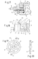
- the third embodiment comes very close to the first embodiment of the invention in that the insert body 9 can in turn be formed as a sheet metal part or injection molded part can.
- the insert body 9 again formed as a disc 11, to which a substantially perpendicular from the Shaped guide sleeve 12 protruding for the coil spring 3 is formed is.
- the disk 11 in turn forms an outer one, in the interior 2 of the housing 1 attachable holding part of the insert body 9, while the guide socket 12 forms a hollow cylindrical guide part for the spring 3, as in the first Implementation of the invention is the case.
- the coil spring engages in the assembled state the guide socket 12 and is on one side on the disc 11.
- the insert body 9 (as in the first embodiment) has an outer one Edge area 13a for attachment to the housing 1, but this is in contrast to first version not closed, but by two arched resilient Arms Q1, Q2 formed in the area of a web 15 between the outer Edge area 13a and the inner ring area 14, which in turn is present converge or are connected.
- the Arms Q1, Q2 can be provided with an edge recess RA at the connection point 15, as can be seen in FIG.
- Those embraced by the poor Q1, Q2 themselves flow passages 8 adjoining it radially inward are in the latter Execution optimally large, since essentially only one web 15 has the valve cross section concentrated.
- the two arcuate resilient arms Q1, Q2 form the outer in this case on the housing 1 attachable holding part by representing locking means that according to Art a spring ring with an inner groove 18 in the wall of the housing (as a corresponding Fasteners) non-positively and positively connected, in particular can be clipped.
- An additional spring ring 17 is thus - as in the second Implementation of the invention - not required.
- the wall of the housing interior also needs 2 advantageously - as in the second embodiment - in the area between the head 6 of the shaft 5 and the inside of the valve plate 4 only one to have two-stage diameter formation.
- the insert body 9 as disc-shaped, flat sheet metal part is formed by a simple punching process is shaped. 19 and 20 corresponds to this Execution as a disk part 32 with respect to the flow passages 8 and the webs 15 in the Essentially the embodiment according to FIG. 4. Only the Guide socket 12. That is why it is with this version of the insert body advantageous if the valve plate 4 on its side facing the insert body 9 a central, essentially hollow cylindrical guide projection 34 for the spring 3 has.
- the housing-side sealing seat 22 is formed as an edge.
- the conical peripheral edge 21 the valve disc 4 thus comes to rest in the closed position with line contact to the sealing seat 22.
- a Inner cone 36 may be provided, which is favorable in the open position Flow properties can be achieved.
- the conical peripheral edge 21 of the Valve plates 4 includes a first cone angle ⁇ 1 with the longitudinal axis, and the Inner cone 36 is aligned at a second cone angle ⁇ 2, the first Cone angle ⁇ 1 larger than the second cone angle ⁇ 2 is around in the closed position to ensure the line contact described.
- the first is preferably located Cone angle ⁇ 1 on the order of about 45 °, and the second cone angle ⁇ 2 is about 30 °.
- the counter spring 19 is formed by an annular body 38 made of a rubber-elastic material (so-called rubber spring).
- a conventional O-ring in a suitable dimension can be used.
- the inventive method Pipe rupture valve at least one throttle channel 40 such that in the Locked position for pressure reduction, a slight pressure medium flow is possible.
- the throttle duct 40 extends as an oblique bore through the valve plate 4, starting from the interior 2 of the housing 1 facing side to the outer peripheral surface. This leads to the Throttle channel 40 radially outward outside of the preferably as a counter spring 19 provided disc spring covered area. Therefore, one can continuous, uninterrupted disc spring can be used.
- the throttle channel 40 has a diameter D in the range of preferably approximately 1 mm.
- the throttle duct 40 is an axial bore trained, therefore, in the area covered by the disc spring after opens on the outside. Therefore, the disc spring - similar to the version shown in Fig. 6 b 'and 7 b - be slotted to form flow openings 42 according to FIG. 24.
- the throttle duct 40 is formed by that the valve plate 4 has a central bore with such a larger one Has a diameter that an annular gap is formed towards the shaft 5. If too a plate spring is used as counter spring 19, this must be corresponding 22 and 24 are slotted. In addition, it is then provided that the Disc spring sits in a flat recess 44 of the valve disc 4 without play in order to fundamentally possible through the annular gap or throttle duct 40 - tilting of the Avoid valve plates 4.
- this is a pre-assembled one Valve unit provided as a so-called valve cartridge (cartridge).
- This unit consists of the valve plate 4, the shaft 5 with its head 6, the Securing element 7 (nut with lock nut 10), the insert body 9 and biased spring 3.
- the counter spring 19 is also provided.
- an insert sleeve 46 is part of the preassembled unit intended. This insert sleeve 46 is in the outer peripheral region between the Insert body 9 and the valve plate 4 arranged. It is so fixed in that Housing 1 used or usable that the insert body 9 axially free of play between themselves and the paragraph 16 already described above in the housing 1. An additional snap ring 17 is therefore not required here.
- the insert sleeve 46 is connected to the valve plate 4 cooperating sealing seat 22.
- the pre-assembled Assembly can be preset, what the opening and closing behavior and relates to the opening cross section of the valve.
- This setting is advantageous regardless of any manufacturing tolerances in the area of the housing 1.
- the insert sleeve 46 has latching means 48 on its outer circumference, which cooperate with corresponding counter-locking means in the housing 1.
- Both Latching means 48 is preferably a radial ring shoulder which is in a corresponding groove-like recess engages in the housing.
- This ring approach 26 upper half a nose or tooth-like cross section or 26, lower half an arched, for example approximately semicircular Have cross-section.
- the insert sleeve 46 can advantageously be made of one material exist, which is harder than the material of the housing 1. For example, it can to deal with hardened steel. This can ensure a high level of security with regard to Bracket in the housing 1 can be reached.
- the descriptive design causes also at the same time a seal of the insert sleeve 46 in the housing 1. Zur The assembly only needs to be inserted axially into the housing 1.
- the invention is not limited to the exemplary embodiments shown, but rather also includes all embodiments having the same effect in the sense of the invention.
- the spring 3 in so far as this as a compression spring element (e.g. made of rubber), or the insert body 9 possible.
- the invention is not based on the combination of features defined in claim 1 limited, but can also be by any other combination of features all of the individual features disclosed are defined. This means that basically omitted or by each individual feature of claim 1 at least one feature disclosed elsewhere in the application is replaced can. In this respect, claim 1 is only a first attempt at formulation for a Understanding invention.
Landscapes
- Engineering & Computer Science (AREA)
- General Engineering & Computer Science (AREA)
- Mechanical Engineering (AREA)
- Safety Valves (AREA)
- Check Valves (AREA)
- Pens And Brushes (AREA)
- Fluid-Pressure Circuits (AREA)
- Magnetically Actuated Valves (AREA)
- Glass Compositions (AREA)
- Lift Valve (AREA)
Abstract
Description
- ein Gehäuse, welches einen Innenraum aufweist,
- einen von einer Feder in eine Offenstellung vorgespannten Ventilteller zum Verschluß des Innenraums, wobei der Ventilteller in einer Verschlußstellung mit einem Umfangsrand an einem korrespondierenden Dichtsitz des Gehäuses anliegt,
- einen Schaft, der einendig einen Kopf zur Anlage der Feder und anderendig mindestens ein die Außenseite des Ventiltellers beaufschlagendes Sicherungselement aufweist,
- einen im Innenraum angeordneten, Strömungsdurchgänge für das Druckmittel aufweisenden Einsatzkörper,
- Fig. 1
- einen Längsschnitt durch eine erste Ausführung eines erfindungsgemäßen Rohrbruchventils,
- Fig. 2
- eine der Fig. 1 entsprechende Darstellung der ersten Ausführung eines erfindungsgemäßen Rohrbruchventils, jedoch in einer vorteilhaften Abwandlung,
- Fig. 3
- eine vergrößerte Darstellung eines Ausschnitts aus Fig. 2,
- Fig. 4
- eine Draufsicht auf das Einsatzteil der ersten Ausführung eines erfindungsgemäßen Rohrbruchventils,
- Fig. 5
- eine Schnittansicht des Einsatzteiles der ersten Ausführung eines erfindungsgemäßen Rohrbruchventils gemäß der Linie V-V in Fig. 4,
- Fig. 6a und 7a, 6b und 7b sowie 6c und 7c
- jeweils zwei Ansichten dreier verschiedener Ausführungen eines Einzelteils der wie in Fig. 2 und 3 abgewandelten ersten Ausführung sowie der wie in Fig. 8 abgewandelten zweiten Ausführung eines erfindungsgemäßen Rohrbruchventils,
- Fig. 8
- eine der Fig. 3 entsprechende Schnittansicht einer zweiten Ausführung eines erfindungsgemäßen Rohrbruchventils,
- Fig. 9
- eine Draufsicht auf das Einsatzteil der zweiten Ausführung eines erfindungsgemäßen Rohrbruchventils,
- Fig. 10
- eine Schnittansicht des Einsatzteiles der zweiten Ausführung eines erfindungsgemäßen Rohrbruchventils,
- Fig. 11
- eine Seitenansicht des Einsatzteiles der zweiten Ausführung eines erfindungsgemäßen Rohrbruchventils,
- Fig. 12
- die Darstellung einer Abwicklung des Einsatzteiles der zweiten Ausführung eines erfindungsgemäßen Rohrbruchventils,
- Fig. 13
- eine qualitative diagrammatische Darstellung der Abhängigkeit der Öffnungsweite des Ventils vom Druck des Druckmittels bei der abgewandelten ersten und zweiten Ausführung eines erfindungsgemäßen Rohrbruchventils, wenn sie sich im normalen Betriebszustand befindet,
- Fig. 14
- eine qualitative diagrammatische Darstellung der Abhängigkeit der Öffnungsweite des Ventils vom Druck des Druckmittels bei allen dargestellten Ausführungen eines erfindungsgemäßen Rohrbruchventils, für den Fall, daß ein Leitungsbruch eintritt,
- Fig. 15
- eine Draufsicht auf das Einsatzteil einer dritten Ausführung eines erfindungsgemäßen Rohrbruchventils,
- Fig. 16
- eine Schnittansicht der dritten Ausführung des Einsatzteiles eines erfindungsgemäßen Rohrbruchventils gemäß der Linie XVI-XVI in Fig. 15,
- Fig. 17
- einen Längsschnitt durch den Ventilbereich einer weiteren Ausführungsvariante des erfindungsgemäßen Rohrbruchventils,
- Fig. 18
- eine Ausschnittvergrößerung aus Fig. 17 im Bereich des Dichtsitzes,
- Fig. 19
- eine Draufsicht des Einsatzteils der Ausführung gemäß Fig. 17,
- Fig. 20
- einen Schnitt des Einsatzteils gemäß Schnittlinie XX - XX in Fig. 19,
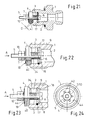
- Fig. 21
- eine weitere Ausführung des Rohrbruchventils im Längsschnitt,
- Fig. 22
- eine Ausführungsvariante in einer vergrößerten Teilschnittansicht,
- Fig. 23
- eine Darstellung analog zu Fig. 22 in einer weiteren Modifikation,
- Fig. 24
- eine axiale Stimansicht in Pfeilrichtung A gemäß Fig. 22, 23,
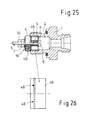
- Fig. 25
- eine weitere Ausführungsform des Rohrbruchventils in einer Darstellung analog Fig. 21 und
- Fig. 26
- ein vergrößertes Einzelteil aus Fig. 25 in Seitenansicht und in zwei verschiedenen Varianten in der oberen und unteren Figurenhälfte.
- 1
- Gehäuse
- 2
- Innenraum von 1
- 3
- Feder
- 4
- Ventilteller
- 5
- Schaft
- 6
- Einstellkopf an 5
- 7
- Mutter auf 5
- 8
- Strömungsdurchgang
- 9
- Einsatzkörper
- 10
- Kontermutter für 7
- 11
- Auflagebereich von 9 für 3 (Scheibe oder Boden)
- 12
- Führungsstutzen von 9 für 3
- 13, 13a
- Randbereich von 9
- 14
- innerer Ringbereich von 9
- 14a
- Bodenbereich von 9
- 15
- Steg zwischen 13 und 14
- 16
- Absatz in 2
- 17
- Sprengring
- 18
- Innennut in 1
- 19
- Gegenfeder
- 20
- Bohrung in 19
- 21
- Umfangsrand von 4
- 22
- Dichtsitz von 1/46
- 23
- Korbarm von 9
- 23a
- Lappen zur Bildung von 23 und 12
- 24
- Randwulst von 9
- 24a
- Lappen zur Bildung von 24
- 25
- Verbindungsabschnitt von 9
- 25a
- Steg zur Bildung von 25
- 26
- Verschluß von 25
- 26a
- Lappen an 25a (Verschlußmittel von 26)
- 26b
- Aussparung in 25a (Verschlußmittel von 26)
- 27
- Außengewindeabschnitt von 1 (4 abgewandt)
- 28
- Innenkonus von 1
- 29
- Außengewindeabschnitt von 1 (4 zugewandt)
- 30
- Dichtungsring
- 32
- Scheibenteil (=9)
- 34
- Führungsansatz (für 3 an 4)
- 36
- Innenkonus
- 38
- Körper (=19)
- 40
- Drosselkanal
- 42
- Öffnungen
- 44
- Vertiefung
- 46
- Einsatzhülse
- 48
- Rastmittel
- A, B, C, D, E
- Druckbereiche
- AW
- Abwicklung von 9
- Dt
- Hubvergrößerung
- FI
- inneres Federbein von 19
- FA
- äußeres Federbein von 19
- H1
- unterer Wert von t im Betriebszustand
- H2
- oberer Wert von t im Betriebszustand
- L
- gegenseitiger Abstand von 23a
- RA
- Randausnehmung in 13a
- S1
- Schlitz in 24
- S2
- Schlitz in 14a, 12
- p
- Druck
- Q1, Q2
- elastische Arme in 13a
- S
- Strömungsrichtung
- t
- Hub von 4
- W
- Wölbung von 19
Claims (29)
dadurch gekennzeichnet, daß der Einsatzkörper (9) als Blechformteil ausgebildet ist.
dadurch gekennzeichnet, daß die Feder (3) als Druckfederelement, insbesondere als Schraubenfeder, ausgebildet ist, wobei der Einsatzkörper (9) ein äußeres, im Innenraum (2) des Gehäuses (1) befestigbares Halteteil (13, 13a, 24) und ein etwa mittig angeordnetes, im Wesentlichen hohlzylindrisches Führungsteil (12) für die Feder (3) aufweist.
dadurch gekennzeichnet, daß die Feder (3) als Druckfederelement, insbesondere als Schraubenfeder, ausgebildet ist, wobei der Einsatzkörper (9) als durch Ausstanzen geformtes, ebenes, gelochtes, Scheibenteil (32) ausgebildet ist, und wobei der Ventilteller (4) auf seiner dem Einsatzkörper (9) zugewandten Seite einen zentrischen, im Wesentlichen hohlzylindrischen Führungsansatz (34) für die Feder (3) aufweist.
dadurch gekennzeichnet, daß der Einsatzkörper (9) als Stanzoder Biege-Stanz-Teil ausgebildet ist.
dadurch gekennzeichnet, daß der Einsatzkörper (9) als ein aus Kunststoff oder Metall bestehendes Spritzgußformteil ausgebildet ist.
dadurch gekennzeichnet, daß der Schaft (5) einstückig ausgebildet ist.
dadurch gekennzeichnet, daß das Sicherungselement (7) als lagesicherbare Mutter ausgebildet ist.
dadurch gekennzeichnet, daß der Kopf (6) als Einstellkopf ausgebildet ist und mit dem Sicherungselement (7) derart zusammenwirkt, daß die Vorspannung der Feder (3) durch relatives Verdrehen des Sicherungselementes (7) und/oder des Einstellkopfes veränderbar ist.
dadurch gekennzeichnet, daß zwischen der Außenseite des Ventiltellers (4) und dem Sicherungselement (7) eine Gegenfeder (19) angeordnet ist, die der der Vorspannung des Ventiltelllers (4) dienenden Feder (3) entgegenwirkt.
dadurch gekennzeichnet, dass die Gegenfeder (19) als Tellerfeder oder als Körper (38) aus einem gummielastischen Material ausgebildet ist.
dadurch gekennzeichnet, daß die Gegenfeder (19) einen Federhub im Bereich von 0,1 bis 5 mm, vorzugsweise von 0,5 mm, aufweist.
dadurch gekennzeichnet, daß der Einsatzkörper (9) als kreisförmige, Durchbrüche aufweisende Scheibe (11) ausgebildet ist, die mit einem Randbereich (13) insbesondere das äußere, im Innenraum (2) des Gehäuses (1) befestigbare Halteteil (13, 13a, 24) bildet und an die vorzugsweise ein im wesentlichen senkrecht von der Scheibenebene abstehender Führungsstutzen (12) angeformt ist, der insbesondere das hohlzylindrische Führungsteil (12) für die Feder (3) bildet.
gekennzeichnet durch Rastmittel (17, 24, Q1, Q2) zur Ausbildung einer lösbaren kraft- und formschlüssigen Verbindung des Einsatzkörpers (9) mit korrespondierenden Befestigungsmitteln (18) der Wand des Innenraums (2) des Gehäuses (1).
dadurch gekennzeichnet, daß der Einsatzkörper (9) durch eine/die lösbare kraft- und formschlüssige Verbindung im Wesentlichen axial spielfrei im Innenraum (2) des Gehäuses (1) festlegbar ist.
dadurch gekennzeichnet, daß die korrespondierenden Befestigungsmittel (18) der Wand des Gehäuses (1) durch eine Innennut (18) in der Wand des Gehäuses (1) gebildet sind.
dadurch gekennzeichnet, daß die Rastmittel (17, 24, Q1, Q2) für den Einsatzkörper (9) durch eine Schlitze (S1) aufweisende Randwulst (24) des Einsatzkörpers (9) gebildet sind, die insbesondere auch das Halteteil (13, 13a, 24) bildet.
dadurch gekennzeichnet, daß die Rastmittel (17, 24, Q1, Q2) für den Einsatzkörper (9) durch zwei in einem, insbesondere das Halteteil (13, 13a, 24) bildenden, Randbereich (13a) des Einsatzkörpers (9) angeordnete, einendig miteinander verbundene bogenförmige federnde Arme (Q1, Q2) gebildet sind.
dadurch gekennzeichnet, daß der Einsatzkörper (9) an einem Absatz (16) des Innenraumes (2) des Gehäuses (1) von einem Sprengring (17) gehalten ist, der insbesondere die Rastmittel für den Einsatzkörper (9) bildet.
dadurch gekennzeichnet, daß der Einsatzkörper (9) als Korb ausgebildet ist, der einen umlaufenden, ringförmigen Verbindungsabschnitt (25) aufweist, an dem oberseitig (die) Rastmittel (13, 13a, 24), insbesondere in Form der Randwulst (24), angeordnet sind, und an dem unterseitig Korbarme (23) angeordnet sind, die an ihrem freien Ende derart abgewinkelt sind, daß sie einen ringförmigen, durch Schlitze (S2) unterbrochenen Bodenbereich (14a) zur Anlage der Feder (3) und einen in Längsrichtung des Gehäuses (1) verlaufenden durch Schlitze (S2) unterbrochenen Führungsstutzen (12) bilden, der insbesondere das hohlzylindrische Führungsteil (12) für die Feder (3) bildet,
wobei die Schlitze (S2) und die Zwischenräume zwischen den Korbarmen (23) die Strömungsdurchgänge (8) für das Druckmittel bilden.
dadurch gekennzeichnet, daß zur Bildung eines geschlossenen (Verschluß 26) ringförmigen Verbindungsabschnittes (25) in einer Abwicklung (AW) des Einsatzkörpers (9) ein Steg (25a) angeordnet ist, an dessen Enden kraft- und/oder formschlüssig zusammenwirkende Verschlußmittel (26a, 26b), wie ein Lappen (26a) und eine Aussparung (26b), angeordnet bzw. ausgebildet sind.
dadurch gekennzeichnet, daß die Wand des Innenraums (2) des Gehäuses (1) im Bereich zwischen dem Einstellkopf (6) des Schaftes (5) und der Innenseite des Ventiltellers (4) in einem Schließzustand des Ventils eine zweistufige Durchmesserausbildung aufweist.
dadurch gekennzeichnet, daßdervonderFeder(3)inOffenstellung vorgespannte Ventilteller (4), der Schaft (5) mit seinem Kopf (6) und dem Sicherungselement (7) sowie der Einsatzkörper (9) und gegebenenfalls die Gegenfeder (19) eine vormontierte Baueinheit bilden.
gekennzeichnet durch eine einen Teil der vormontierten Baueinheit bildende Einsatzhülse (46), die im äußeren Umfangsbereich zwischen dem Einsatzkörper (9) und dem Ventilteller (4) angeordnet ist, und die derart fixiert in das Gehäuse (1) einsetzbar oder eingesetzt ist, dass sie den Einsatzkörper (9) axial zwischen sich und einem Absatz (16) im Gehäuse (1) festlegt.
dadurch gekennzeichnet, dass die Einsatzhülse (46) den mit dem Ventilteller (4) zusammenwirkenden Dichtsitz (22) aufweist.
dadurch gekennzeichnet, dass die Einsatzhülse (46) auf ihrem Außenumfang Rastmittel (48) aufweist, die mit korrespondierenden Gegenrastmitteln im Gehäuse (1) zusammenwirken.
gekennzeichnet durch mindestens einen in der Verschlußstellung des Ventiltellers (4) eine geringfügige Druckabbau-Strömung des Druckmittels zulassenden Drosselkanal (40).
dadurch gekennzeichnet, daß das von dem Ventilteller (4) abgekehrte Ende des Gehäuses (1) mit einem Außengewindeabschnitt (27) und einem Innenkonus (28) zum Eingriff eines konischen Schneidringes versehen ist, der ein Anschlußrohr umgibt und von einer auf dem Außengewindeabschnitt (27) aufgeschraubten Mutter in Eingriff mit dem Innenkonus (28) gehalten wird.
dadurch gekennzeichnet, daß das dem Ventilteller (4) zugekehrte Ende des Gehäuses (1) für die Verschraubung mit einem nachgeordneten Teil der Druckmittelleitung einen Außengewindeabschnitt (29) aufweist.
dadurch gekennzeichnet, daß die Außenabmaße des Gehäuses (1), insbesondere dessen Außengewindeabschnitte (27, 29), in genormter Größe ausgeführt sind.
Priority Applications (1)
| Application Number | Priority Date | Filing Date | Title |
|---|---|---|---|
| EP05106600A EP1605193A1 (de) | 2001-11-23 | 2002-11-22 | Rohrbruchventil |
Applications Claiming Priority (2)
| Application Number | Priority Date | Filing Date | Title |
|---|---|---|---|
| DE20119058U | 2001-11-23 | ||
| DE20119058U DE20119058U1 (de) | 2001-11-23 | 2001-11-23 | Rohrbruchventil |
Related Child Applications (1)
| Application Number | Title | Priority Date | Filing Date |
|---|---|---|---|
| EP05106600A Division EP1605193A1 (de) | 2001-11-23 | 2002-11-22 | Rohrbruchventil |
Publications (3)
| Publication Number | Publication Date |
|---|---|
| EP1314921A2 true EP1314921A2 (de) | 2003-05-28 |
| EP1314921A3 EP1314921A3 (de) | 2003-11-12 |
| EP1314921B1 EP1314921B1 (de) | 2006-01-25 |
Family
ID=7964339
Family Applications (2)
| Application Number | Title | Priority Date | Filing Date |
|---|---|---|---|
| EP02026080A Expired - Lifetime EP1314921B1 (de) | 2001-11-23 | 2002-11-22 | Rohrbruchventil |
| EP05106600A Withdrawn EP1605193A1 (de) | 2001-11-23 | 2002-11-22 | Rohrbruchventil |
Family Applications After (1)
| Application Number | Title | Priority Date | Filing Date |
|---|---|---|---|
| EP05106600A Withdrawn EP1605193A1 (de) | 2001-11-23 | 2002-11-22 | Rohrbruchventil |
Country Status (5)
| Country | Link |
|---|---|
| EP (2) | EP1314921B1 (de) |
| AT (1) | ATE316630T1 (de) |
| DE (2) | DE20119058U1 (de) |
| DK (1) | DK1314921T3 (de) |
| ES (1) | ES2256393T3 (de) |
Cited By (8)
| Publication number | Priority date | Publication date | Assignee | Title |
|---|---|---|---|---|
| EP1503121A1 (de) | 2003-07-31 | 2005-02-02 | HAWE Hydraulik GmbH & Co. KG | Schlauchbruch-Ventil |
| EP1508730A1 (de) * | 2003-08-22 | 2005-02-23 | Metallwerke Otto Dingerkus GmbH | Strömungswächter zum automatischen Absperren von mit Fluid durchströmten Leitungen |
| DE202004002066U1 (de) * | 2004-02-11 | 2005-06-30 | Weber, Gisela | Rohrbruchventil |
| EP1564462A1 (de) * | 2004-02-11 | 2005-08-17 | WEBER, Gisela | Rohrbruchventil |
| DE102004006664A1 (de) * | 2004-02-11 | 2005-09-01 | Gisela Weber | Rohrbruchventil |
| EP2157321A1 (de) | 2008-08-19 | 2010-02-24 | HAWE Hydraulik SE | Einschraubverschraubung |
| WO2012110268A1 (de) * | 2011-02-16 | 2012-08-23 | Voss Fluid Gmbh | Einschraubzapfen für eine rohrverschraubung sowie zugehöriger profildichtring |
| US20210404568A1 (en) * | 2018-12-14 | 2021-12-30 | Halliburton Energy Services, Inc. | Pump valve guide for hydraulic fracturing |
Families Citing this family (5)
| Publication number | Priority date | Publication date | Assignee | Title |
|---|---|---|---|---|
| DE102007010227A1 (de) | 2007-03-02 | 2008-09-04 | Mertik Maxitrol Gmbh & Co. Kg | Gasströmungswächter |
| DE102009020875B4 (de) * | 2009-05-12 | 2014-12-04 | Mertik Maxitrol Gmbh & Co. Kg | Vorrichtung zur Einbringung einer Absperreinrichtung in eine Rohrleitung |
| DE102009036201B4 (de) | 2009-07-31 | 2011-07-07 | Mertik Maxitrol GmbH & Co. KG, 06502 | Gasströmungswächter |
| DE102013105170B4 (de) | 2013-05-21 | 2017-05-11 | Gisela Weber | Rohrbruchventil, insbesondere zur Sicherung gegen Leckagen einer Hydraulikleitung und Verfahren zu dessen Ausbildung |
| DE102022106748A1 (de) | 2022-03-23 | 2023-09-28 | Schaeffler Technologies AG & Co. KG | Ventil |
Citations (11)
| Publication number | Priority date | Publication date | Assignee | Title |
|---|---|---|---|---|
| US1901982A (en) * | 1931-09-26 | 1933-03-21 | Theodore M Pardue | Closure for receptacles |
| US2647533A (en) * | 1951-12-17 | 1953-08-04 | Irrigation Equipment Co Inc | Drain plug for pipe lines |
| US3749122A (en) * | 1971-04-27 | 1973-07-31 | H Gold | System for installing fluid elements in conduit circuits |
| AU470376B2 (en) * | 1972-11-22 | 1976-03-11 | Jamec Tools Pty. Ltd. | Improved valve |
| US4295412A (en) * | 1978-12-19 | 1981-10-20 | Nissin Kogyo Kabushiki Kaisha | Hose with a one-way valve for a vacuum operated servomotor |
| FR2636379A1 (fr) * | 1988-09-09 | 1990-03-16 | Lucas Georges Ets | Clapet antirebond de securite pour verin fluidique ou analogue |
| US5293898A (en) * | 1990-07-06 | 1994-03-15 | Pipelife Rohrsysteme Gesellschaft M.B.H. | Safety cut-out |
| US5755259A (en) * | 1993-01-09 | 1998-05-26 | Mertik Maxitrol Gmbh & Co., Kg | Safety shut-off for gas lines |
| JPH10332093A (ja) * | 1997-06-04 | 1998-12-15 | Yasusada Sakai | ガス放出防止装置付ガス容器バルブ |
| DE29818904U1 (de) * | 1998-10-23 | 1999-01-28 | Mertik Maxitrol GmbH & Co KG, 06502 Thale | Gasströmungswächter |
| WO2002016813A1 (de) * | 2000-08-23 | 2002-02-28 | Gisela Weber | Hydraulikventil |
Family Cites Families (4)
| Publication number | Priority date | Publication date | Assignee | Title |
|---|---|---|---|---|
| GB556863A (en) | 1941-05-16 | 1943-10-26 | Acrotorque Co | Improvements relating to automatic shut-off valves |
| US4022113A (en) * | 1975-12-10 | 1977-05-10 | Blatt Leland F | Flow control valve |
| US5950658A (en) * | 1997-12-11 | 1999-09-14 | Hoeptner, Iii; Herbert W. | Fluid flow deverter unit |
| DE20015378U1 (de) * | 2000-09-06 | 2000-12-28 | Mertik Maxitrol GmbH & Co. KG, 06484 Quedlinburg | Gasströmungswächter |
-
2001
- 2001-11-23 DE DE20119058U patent/DE20119058U1/de not_active Expired - Lifetime
-
2002
- 2002-11-22 AT AT02026080T patent/ATE316630T1/de active
- 2002-11-22 EP EP02026080A patent/EP1314921B1/de not_active Expired - Lifetime
- 2002-11-22 EP EP05106600A patent/EP1605193A1/de not_active Withdrawn
- 2002-11-22 DE DE50205696T patent/DE50205696D1/de not_active Expired - Lifetime
- 2002-11-22 ES ES02026080T patent/ES2256393T3/es not_active Expired - Lifetime
- 2002-11-22 DK DK02026080T patent/DK1314921T3/da active
Patent Citations (11)
| Publication number | Priority date | Publication date | Assignee | Title |
|---|---|---|---|---|
| US1901982A (en) * | 1931-09-26 | 1933-03-21 | Theodore M Pardue | Closure for receptacles |
| US2647533A (en) * | 1951-12-17 | 1953-08-04 | Irrigation Equipment Co Inc | Drain plug for pipe lines |
| US3749122A (en) * | 1971-04-27 | 1973-07-31 | H Gold | System for installing fluid elements in conduit circuits |
| AU470376B2 (en) * | 1972-11-22 | 1976-03-11 | Jamec Tools Pty. Ltd. | Improved valve |
| US4295412A (en) * | 1978-12-19 | 1981-10-20 | Nissin Kogyo Kabushiki Kaisha | Hose with a one-way valve for a vacuum operated servomotor |
| FR2636379A1 (fr) * | 1988-09-09 | 1990-03-16 | Lucas Georges Ets | Clapet antirebond de securite pour verin fluidique ou analogue |
| US5293898A (en) * | 1990-07-06 | 1994-03-15 | Pipelife Rohrsysteme Gesellschaft M.B.H. | Safety cut-out |
| US5755259A (en) * | 1993-01-09 | 1998-05-26 | Mertik Maxitrol Gmbh & Co., Kg | Safety shut-off for gas lines |
| JPH10332093A (ja) * | 1997-06-04 | 1998-12-15 | Yasusada Sakai | ガス放出防止装置付ガス容器バルブ |
| DE29818904U1 (de) * | 1998-10-23 | 1999-01-28 | Mertik Maxitrol GmbH & Co KG, 06502 Thale | Gasströmungswächter |
| WO2002016813A1 (de) * | 2000-08-23 | 2002-02-28 | Gisela Weber | Hydraulikventil |
Non-Patent Citations (1)
| Title |
|---|
| PATENT ABSTRACTS OF JAPAN vol. 1999, no. 03, 31. März 1999 (1999-03-31) & JP 10 332093 A (SAKAI YASUSADA;TAGUCHI SHOTEN:KK), 15. Dezember 1998 (1998-12-15) * |
Cited By (11)
| Publication number | Priority date | Publication date | Assignee | Title |
|---|---|---|---|---|
| EP1503121A1 (de) | 2003-07-31 | 2005-02-02 | HAWE Hydraulik GmbH & Co. KG | Schlauchbruch-Ventil |
| EP1508730A1 (de) * | 2003-08-22 | 2005-02-23 | Metallwerke Otto Dingerkus GmbH | Strömungswächter zum automatischen Absperren von mit Fluid durchströmten Leitungen |
| DE202004002066U1 (de) * | 2004-02-11 | 2005-06-30 | Weber, Gisela | Rohrbruchventil |
| EP1564462A1 (de) * | 2004-02-11 | 2005-08-17 | WEBER, Gisela | Rohrbruchventil |
| DE102004006664A1 (de) * | 2004-02-11 | 2005-09-01 | Gisela Weber | Rohrbruchventil |
| DE102004006663A1 (de) * | 2004-02-11 | 2005-09-22 | Gisela Weber | Rohrbruchventil |
| DE102004006663B4 (de) * | 2004-02-11 | 2005-12-29 | Gisela Weber | Rohrbruchventil |
| EP2157321A1 (de) | 2008-08-19 | 2010-02-24 | HAWE Hydraulik SE | Einschraubverschraubung |
| WO2012110268A1 (de) * | 2011-02-16 | 2012-08-23 | Voss Fluid Gmbh | Einschraubzapfen für eine rohrverschraubung sowie zugehöriger profildichtring |
| US20210404568A1 (en) * | 2018-12-14 | 2021-12-30 | Halliburton Energy Services, Inc. | Pump valve guide for hydraulic fracturing |
| US11859723B2 (en) * | 2018-12-14 | 2024-01-02 | Halliburton Energy Services, Inc. | Pump valve guide for hydraulic fracturing |
Also Published As
| Publication number | Publication date |
|---|---|
| DE50205696D1 (de) | 2006-04-13 |
| EP1314921A3 (de) | 2003-11-12 |
| ATE316630T1 (de) | 2006-02-15 |
| DE20119058U1 (de) | 2003-04-03 |
| DK1314921T3 (da) | 2006-03-06 |
| ES2256393T3 (es) | 2006-07-16 |
| EP1314921B1 (de) | 2006-01-25 |
| EP1605193A1 (de) | 2005-12-14 |
| EP1605193A8 (de) | 2006-03-15 |
Similar Documents
| Publication | Publication Date | Title |
|---|---|---|
| EP2003346B1 (de) | Befestigungseinrichtung mit Toleranzausgleich | |
| EP2977656A1 (de) | Stellarmatur | |
| EP3004702B1 (de) | Kombination aus einem gehäuse und einem ventil | |
| EP1314921B1 (de) | Rohrbruchventil | |
| EP1228925A2 (de) | Befestigungsvorrichtung für Heckleuchten von Fahrzeugen, vorzugsweise von Kraftfahrzeugen | |
| EP1415096A2 (de) | Bauteilverbund, insbesondere ventil, und verfahren zur herstellung desselben | |
| EP1084926B1 (de) | Halterung für eine Druckleitung | |
| EP3516242B1 (de) | Toleranzausgleichselement | |
| EP1828623B1 (de) | Vorrichtung zum befestigen eines anbauteils und eines trägerteiles in einem abstand voneinander | |
| DE3831554C2 (de) | Drosselrückschlagventil | |
| AT396815B (de) | Armatur für ein thermostatventil | |
| EP3556621B1 (de) | Druckbegrenzungsventil | |
| DE10302984B3 (de) | Säuleneinheit | |
| EP1090240B1 (de) | Druckbegrenzungsventil | |
| DE29709021U1 (de) | Rückschlagventil | |
| EP2787222B1 (de) | Vorrichtung und Anordnung zur Verriegelung von schraubbaren Elementen | |
| DE4430922B4 (de) | Arretierelement, versehen mit Maßnahmen zur Lagesicherung, die am Käfig sowie am Führungsteil vorgesehen sind | |
| DE2449443A1 (de) | Rueckschlagventil | |
| WO1996029182A1 (de) | Futter mit kupplung | |
| DE102004025969A1 (de) | Magnetventil | |
| DE4023123C2 (de) | Sicherung für Schraubenmuttern oder drehbar angeordnete Teile gegen Lösen | |
| DE20009766U1 (de) | Ventil | |
| EP1503121A1 (de) | Schlauchbruch-Ventil | |
| DE20108618U1 (de) | Ventil, insbesondere Absteuer- oder Umgehungsventil für ein fluides Medium | |
| EP0121580A1 (de) | Papierlocher |
Legal Events
| Date | Code | Title | Description |
|---|---|---|---|
| PUAI | Public reference made under article 153(3) epc to a published international application that has entered the european phase |
Free format text: ORIGINAL CODE: 0009012 |
|
| AK | Designated contracting states |
Designated state(s): AT BE BG CH CY CZ DE DK EE ES FI FR GB GR IE IT LI LU MC NL PT SE SK TR |
|
| AX | Request for extension of the european patent |
Extension state: AL LT LV MK RO SI |
|
| PUAL | Search report despatched |
Free format text: ORIGINAL CODE: 0009013 |
|
| AK | Designated contracting states |
Kind code of ref document: A3 Designated state(s): AT BE BG CH CY CZ DE DK EE ES FI FR GB GR IE IT LI LU MC NL PT SE SK TR |
|
| AX | Request for extension of the european patent |
Extension state: AL LT LV MK RO SI |
|
| 17P | Request for examination filed |
Effective date: 20040319 |
|
| 17Q | First examination report despatched |
Effective date: 20040513 |
|
| AKX | Designation fees paid |
Designated state(s): AT BE BG CH CY CZ DE DK EE ES FI FR GB GR IE IT LI LU MC NL PT SE SK TR |
|
| GRAP | Despatch of communication of intention to grant a patent |
Free format text: ORIGINAL CODE: EPIDOSNIGR1 |
|
| GRAS | Grant fee paid |
Free format text: ORIGINAL CODE: EPIDOSNIGR3 |
|
| GRAA | (expected) grant |
Free format text: ORIGINAL CODE: 0009210 |
|
| AK | Designated contracting states |
Kind code of ref document: B1 Designated state(s): AT BE BG CH CY CZ DE DK EE ES FI FR GB GR IE IT LI LU MC NL PT SE SK TR |
|
| PG25 | Lapsed in a contracting state [announced via postgrant information from national office to epo] |
Ref country code: IT Free format text: LAPSE BECAUSE OF FAILURE TO SUBMIT A TRANSLATION OF THE DESCRIPTION OR TO PAY THE FEE WITHIN THE PRESCRIBED TIME-LIMIT;WARNING: LAPSES OF ITALIAN PATENTS WITH EFFECTIVE DATE BEFORE 2007 MAY HAVE OCCURRED AT ANY TIME BEFORE 2007. THE CORRECT EFFECTIVE DATE MAY BE DIFFERENT FROM THE ONE RECORDED. Effective date: 20060125 Ref country code: IE Free format text: LAPSE BECAUSE OF FAILURE TO SUBMIT A TRANSLATION OF THE DESCRIPTION OR TO PAY THE FEE WITHIN THE PRESCRIBED TIME-LIMIT Effective date: 20060125 Ref country code: GB Free format text: LAPSE BECAUSE OF FAILURE TO SUBMIT A TRANSLATION OF THE DESCRIPTION OR TO PAY THE FEE WITHIN THE PRESCRIBED TIME-LIMIT Effective date: 20060125 Ref country code: SK Free format text: LAPSE BECAUSE OF FAILURE TO SUBMIT A TRANSLATION OF THE DESCRIPTION OR TO PAY THE FEE WITHIN THE PRESCRIBED TIME-LIMIT Effective date: 20060125 Ref country code: NL Free format text: LAPSE BECAUSE OF FAILURE TO SUBMIT A TRANSLATION OF THE DESCRIPTION OR TO PAY THE FEE WITHIN THE PRESCRIBED TIME-LIMIT Effective date: 20060125 |
|
| REG | Reference to a national code |
Ref country code: GB Ref legal event code: FG4D Free format text: NOT ENGLISH |
|
| REG | Reference to a national code |
Ref country code: CH Ref legal event code: NV Representative=s name: BRAUNPAT BRAUN EDER AG Ref country code: CH Ref legal event code: EP |
|
| REG | Reference to a national code |
Ref country code: IE Ref legal event code: FG4D Free format text: LANGUAGE OF EP DOCUMENT: GERMAN |
|
| REG | Reference to a national code |
Ref country code: DK Ref legal event code: T3 |
|
| REF | Corresponds to: |
Ref document number: 50205696 Country of ref document: DE Date of ref document: 20060413 Kind code of ref document: P |
|
| REG | Reference to a national code |
Ref country code: SE Ref legal event code: TRGR |
|
| PG25 | Lapsed in a contracting state [announced via postgrant information from national office to epo] |
Ref country code: BG Free format text: LAPSE BECAUSE OF FAILURE TO SUBMIT A TRANSLATION OF THE DESCRIPTION OR TO PAY THE FEE WITHIN THE PRESCRIBED TIME-LIMIT Effective date: 20060425 |
|
| PG25 | Lapsed in a contracting state [announced via postgrant information from national office to epo] |
Ref country code: PT Free format text: LAPSE BECAUSE OF FAILURE TO SUBMIT A TRANSLATION OF THE DESCRIPTION OR TO PAY THE FEE WITHIN THE PRESCRIBED TIME-LIMIT Effective date: 20060626 |
|
| NLV1 | Nl: lapsed or annulled due to failure to fulfill the requirements of art. 29p and 29m of the patents act | ||
| ET | Fr: translation filed | ||
| REG | Reference to a national code |
Ref country code: ES Ref legal event code: FG2A Ref document number: 2256393 Country of ref document: ES Kind code of ref document: T3 |
|
| GBV | Gb: ep patent (uk) treated as always having been void in accordance with gb section 77(7)/1977 [no translation filed] |
Effective date: 20060125 |
|
| REG | Reference to a national code |
Ref country code: IE Ref legal event code: FD4D |
|
| PG25 | Lapsed in a contracting state [announced via postgrant information from national office to epo] |
Ref country code: MC Free format text: LAPSE BECAUSE OF NON-PAYMENT OF DUE FEES Effective date: 20061130 Ref country code: BE Free format text: LAPSE BECAUSE OF NON-PAYMENT OF DUE FEES Effective date: 20061130 |
|
| PLBE | No opposition filed within time limit |
Free format text: ORIGINAL CODE: 0009261 |
|
| STAA | Information on the status of an ep patent application or granted ep patent |
Free format text: STATUS: NO OPPOSITION FILED WITHIN TIME LIMIT |
|
| 26N | No opposition filed |
Effective date: 20061026 |
|
| BERE | Be: lapsed |
Owner name: VOSS FLUID G.M.B.H. + CO. KG Effective date: 20061130 |
|
| REG | Reference to a national code |
Ref country code: CH Ref legal event code: PFA Owner name: VOSS FLUID GMBH Free format text: VOSS FLUID GMBH + CO. KG#LUEDENSCHEIDER STRASSE 52-54#51688 WIPPERFUERTH (DE) -TRANSFER TO- VOSS FLUID GMBH#LUEDENSCHEIDER STRASSE 52-54#51688 WIPPERFUERTH (DE) |
|
| PG25 | Lapsed in a contracting state [announced via postgrant information from national office to epo] |
Ref country code: GR Free format text: LAPSE BECAUSE OF FAILURE TO SUBMIT A TRANSLATION OF THE DESCRIPTION OR TO PAY THE FEE WITHIN THE PRESCRIBED TIME-LIMIT Effective date: 20060426 Ref country code: CZ Free format text: LAPSE BECAUSE OF FAILURE TO SUBMIT A TRANSLATION OF THE DESCRIPTION OR TO PAY THE FEE WITHIN THE PRESCRIBED TIME-LIMIT Effective date: 20060125 |
|
| PG25 | Lapsed in a contracting state [announced via postgrant information from national office to epo] |
Ref country code: EE Free format text: LAPSE BECAUSE OF FAILURE TO SUBMIT A TRANSLATION OF THE DESCRIPTION OR TO PAY THE FEE WITHIN THE PRESCRIBED TIME-LIMIT Effective date: 20060125 |
|
| PG25 | Lapsed in a contracting state [announced via postgrant information from national office to epo] |
Ref country code: LU Free format text: LAPSE BECAUSE OF NON-PAYMENT OF DUE FEES Effective date: 20061122 Ref country code: TR Free format text: LAPSE BECAUSE OF FAILURE TO SUBMIT A TRANSLATION OF THE DESCRIPTION OR TO PAY THE FEE WITHIN THE PRESCRIBED TIME-LIMIT Effective date: 20060125 |
|
| REG | Reference to a national code |
Ref country code: FR Ref legal event code: CJ |
|
| PG25 | Lapsed in a contracting state [announced via postgrant information from national office to epo] |
Ref country code: CY Free format text: LAPSE BECAUSE OF FAILURE TO SUBMIT A TRANSLATION OF THE DESCRIPTION OR TO PAY THE FEE WITHIN THE PRESCRIBED TIME-LIMIT Effective date: 20060125 |
|
| PGFP | Annual fee paid to national office [announced via postgrant information from national office to epo] |
Ref country code: ES Payment date: 20081117 Year of fee payment: 7 Ref country code: FI Payment date: 20081112 Year of fee payment: 7 |
|
| PGFP | Annual fee paid to national office [announced via postgrant information from national office to epo] |
Ref country code: IT Payment date: 20081027 Year of fee payment: 7 |
|
| PGFP | Annual fee paid to national office [announced via postgrant information from national office to epo] |
Ref country code: FR Payment date: 20081112 Year of fee payment: 7 |
|
| REG | Reference to a national code |
Ref country code: FR Ref legal event code: ST Effective date: 20100730 |
|
| PG25 | Lapsed in a contracting state [announced via postgrant information from national office to epo] |
Ref country code: FI Free format text: LAPSE BECAUSE OF NON-PAYMENT OF DUE FEES Effective date: 20091122 |
|
| PG25 | Lapsed in a contracting state [announced via postgrant information from national office to epo] |
Ref country code: FR Free format text: LAPSE BECAUSE OF NON-PAYMENT OF DUE FEES Effective date: 20091130 |
|
| PGFP | Annual fee paid to national office [announced via postgrant information from national office to epo] |
Ref country code: AT Payment date: 20101110 Year of fee payment: 9 |
|
| PG25 | Lapsed in a contracting state [announced via postgrant information from national office to epo] |
Ref country code: IT Free format text: LAPSE BECAUSE OF NON-PAYMENT OF DUE FEES Effective date: 20091122 |
|
| REG | Reference to a national code |
Ref country code: ES Ref legal event code: FD2A Effective date: 20111116 |
|
| PG25 | Lapsed in a contracting state [announced via postgrant information from national office to epo] |
Ref country code: ES Free format text: LAPSE BECAUSE OF NON-PAYMENT OF DUE FEES Effective date: 20091123 |
|
| PGFP | Annual fee paid to national office [announced via postgrant information from national office to epo] |
Ref country code: SE Payment date: 20111115 Year of fee payment: 10 Ref country code: CH Payment date: 20111114 Year of fee payment: 10 Ref country code: DK Payment date: 20111110 Year of fee payment: 10 |
|
| PGFP | Annual fee paid to national office [announced via postgrant information from national office to epo] |
Ref country code: DE Payment date: 20120131 Year of fee payment: 10 |
|
| REG | Reference to a national code |
Ref country code: CH Ref legal event code: PL |
|
| REG | Reference to a national code |
Ref country code: DK Ref legal event code: EBP |
|
| REG | Reference to a national code |
Ref country code: AT Ref legal event code: MM01 Ref document number: 316630 Country of ref document: AT Kind code of ref document: T Effective date: 20121122 |
|
| PG25 | Lapsed in a contracting state [announced via postgrant information from national office to epo] |
Ref country code: AT Free format text: LAPSE BECAUSE OF NON-PAYMENT OF DUE FEES Effective date: 20121122 Ref country code: CH Free format text: LAPSE BECAUSE OF NON-PAYMENT OF DUE FEES Effective date: 20121130 Ref country code: SE Free format text: LAPSE BECAUSE OF NON-PAYMENT OF DUE FEES Effective date: 20121123 Ref country code: LI Free format text: LAPSE BECAUSE OF NON-PAYMENT OF DUE FEES Effective date: 20121130 |
|
| REG | Reference to a national code |
Ref country code: DE Ref legal event code: R119 Ref document number: 50205696 Country of ref document: DE Effective date: 20130601 |
|
| PG25 | Lapsed in a contracting state [announced via postgrant information from national office to epo] |
Ref country code: DK Free format text: LAPSE BECAUSE OF NON-PAYMENT OF DUE FEES Effective date: 20121130 Ref country code: DE Free format text: LAPSE BECAUSE OF NON-PAYMENT OF DUE FEES Effective date: 20130601 |