EP1314591B1 - Fahrzeug-Zusatzheizgerät und Sicherheitsvorrichtung für ein solches Zusatzheizgerät - Google Patents
Fahrzeug-Zusatzheizgerät und Sicherheitsvorrichtung für ein solches Zusatzheizgerät Download PDFInfo
- Publication number
- EP1314591B1 EP1314591B1 EP02026084A EP02026084A EP1314591B1 EP 1314591 B1 EP1314591 B1 EP 1314591B1 EP 02026084 A EP02026084 A EP 02026084A EP 02026084 A EP02026084 A EP 02026084A EP 1314591 B1 EP1314591 B1 EP 1314591B1
- Authority
- EP
- European Patent Office
- Prior art keywords
- signal
- output
- monoflop
- heater
- vehicle
- Prior art date
- Legal status (The legal status is an assumption and is not a legal conclusion. Google has not performed a legal analysis and makes no representation as to the accuracy of the status listed.)
- Revoked
Links
Images
Classifications
-
- B—PERFORMING OPERATIONS; TRANSPORTING
- B60—VEHICLES IN GENERAL
- B60H—ARRANGEMENTS OF HEATING, COOLING, VENTILATING OR OTHER AIR-TREATING DEVICES SPECIALLY ADAPTED FOR PASSENGER OR GOODS SPACES OF VEHICLES
- B60H1/00—Heating, cooling or ventilating devices
- B60H1/22—Heating, cooling or ventilating devices the heat source being other than the propulsion plant
- B60H1/2203—Heating, cooling or ventilating devices the heat source being other than the propulsion plant the heat being derived from burners
- B60H1/2206—Heating, cooling or ventilating devices the heat source being other than the propulsion plant the heat being derived from burners controlling the operation of burners
-
- B—PERFORMING OPERATIONS; TRANSPORTING
- B60—VEHICLES IN GENERAL
- B60H—ARRANGEMENTS OF HEATING, COOLING, VENTILATING OR OTHER AIR-TREATING DEVICES SPECIALLY ADAPTED FOR PASSENGER OR GOODS SPACES OF VEHICLES
- B60H1/00—Heating, cooling or ventilating devices
- B60H1/00642—Control systems or circuits; Control members or indication devices for heating, cooling or ventilating devices
- B60H1/00978—Control systems or circuits characterised by failure of detection or safety means; Diagnostic methods
-
- B—PERFORMING OPERATIONS; TRANSPORTING
- B60—VEHICLES IN GENERAL
- B60H—ARRANGEMENTS OF HEATING, COOLING, VENTILATING OR OTHER AIR-TREATING DEVICES SPECIALLY ADAPTED FOR PASSENGER OR GOODS SPACES OF VEHICLES
- B60H1/00—Heating, cooling or ventilating devices
- B60H1/22—Heating, cooling or ventilating devices the heat source being other than the propulsion plant
- B60H2001/2228—Heating, cooling or ventilating devices the heat source being other than the propulsion plant controlling the operation of heaters
- B60H2001/2231—Heating, cooling or ventilating devices the heat source being other than the propulsion plant controlling the operation of heaters for proper or safe operation of the heater
-
- B—PERFORMING OPERATIONS; TRANSPORTING
- B60—VEHICLES IN GENERAL
- B60H—ARRANGEMENTS OF HEATING, COOLING, VENTILATING OR OTHER AIR-TREATING DEVICES SPECIALLY ADAPTED FOR PASSENGER OR GOODS SPACES OF VEHICLES
- B60H1/00—Heating, cooling or ventilating devices
- B60H1/22—Heating, cooling or ventilating devices the heat source being other than the propulsion plant
- B60H2001/2246—Heating, cooling or ventilating devices the heat source being other than the propulsion plant obtaining information from a variable, e.g. by means of a sensor
- B60H2001/2256—Heating, cooling or ventilating devices the heat source being other than the propulsion plant obtaining information from a variable, e.g. by means of a sensor related to the operation of the heater itself, e.g. flame detection or overheating
Definitions
- the invention relates to a vehicle auxiliary heater and one for such auxiliary heater provided safety device.
- Vehicle auxiliary heaters are known in various embodiments.
- Basic elements of the heaters are a burner with igniter, one Dosing device with a fuel metering pump and a control device, the operation of the auxiliary heater regardless of the operation of the vehicle, z.
- the control device consists in modern auxiliary heaters from a microcontroller, the dependent on him supplied input information, for example Heating demand, the fuel metering pump, the ignition device and the like controls.
- the z. B. on one Output line generates a drive signal for the fuel metering pump.
- the invention is based on the object, a vehicle auxiliary heater of the above specify type mentioned, in which a disturbance of the control device, in particular the control device designed as a microcontroller is intercepted that a dangerous operating state of the heater is avoided, in particular Controlled uncontrollable operation of the dosing pump of the heater becomes.
- a vehicle auxiliary heater of the aforementioned Art ie an auxiliary heater with a fuel metering pump and a control device that outputs drive signals for the metering pump, by a retriggerable monoflop that is periodic at an input Set signals from the controller receives, and therefore at an output constantly outputs a continuous signal, which is at a first input of an AND Gating element is given, the second input of the drive signal is supplied from the control device, and its output with an actuator the metering pump is connected.
- a retriggerable or retriggerable monoflop is well known. It will Also called monoflop without recovery time.
- a "monoflop” is a monostable device, the z. From a rising one or falling pulse edge is brought into a state in which it its output a high level signal during a predetermined period of time outputs. After this period, the signal goes to the output of the Monoflops automatically return to a ground state.
- the one predetermined Time duration impulse at the output of the monoflop has z. B. one high level, while the ground state corresponds to a low level.
- a retriggerable or retriggerable monoflop is different from that above-mentioned general monoflop in that when feeding a new trigger pulse at its input for the time period preset in it at the output the signal then delivered and only then again returns to the ground state. So you give to the entrance of a retriggerable or retriggerable monoflops a pulse train whose impulses a Have period that is shorter than the period of the monoflop upon receipt of a single pulse output pulse, it is through continuous re-triggering of the monoflop at the output of a continuous signal, z. B. produces a continuous signal with a high level.
- the idea according to the invention is now based on the knowledge that a defect-free working one Microcontroller can issue a periodic set signal, which is the output a re-triggerable monoflop constantly on the active, for example high level, whereas a microcontroller affected by a disturbance such a periodic set signal does not output, so that accordingly at a Disturbance also the output signal of the Monoflops short time after discontinuation of the periodic set signal passes from the microcontroller in the ground state.
- the actuator with which the metering pump is switched on and off is preferably a transistor or an equivalent device.
- the dosing pump is z. Between the collector of the transistor and the battery voltage, while the emitter of the transistor is grounded.
- the inventive measure can in a complete, new auxiliary heating be realized for a vehicle, but also as a separate component with discrete Monoflop and discrete link, so can also be used as a retrofit kit be designed for existing vehicle auxiliary heaters.
- the above-mentioned AND gate can also be replaced by a equivalent link, for example by a NAND gate, if the Level of the signals are changed accordingly.
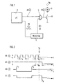
- Fig. 1 shows a block diagram of a safety device for an additional heater of a Motor vehicle, for example, a truck or cars.
- auxiliary heaters are well known and therefore need not be explained in detail here to become. It is z. B. referred to numerous patents and patent applications the assignee of the present invention.
- An essential part of an auxiliary heater for a vehicle is a Control device, with the u. a. the operation of a fuel metering pump controlled which meters the burner of the heater fuel.
- Fig. 1 shows a control device in the form of a microcontroller ( ⁇ C) 2, the in not shown here, different input signals of adjusting devices, Receives sensors or the like, and to various devices of the heater control signals and control signals are.
- ⁇ C microcontroller
- the output signals of the microcontroller 2 of interest here are a drive signal AS and a retrigger signal RS .
- the retrigger signal is applied to the input of a retriggerable or retriggerable monoflop 3.
- T R the retrigger signal having a certain period duration
- the monoflop 3 outputs a continuous signal DS at its output off with a high level.
- retrigger signal RS is shown at 0. at is the continuous signal output from the monoflop 3 shown.
- Fig. 2 the output from the microcontroller 2 drive signal AS.
- This drive signal AS initially have a high level, then go to low level at t 1 , in order then to go high at t 2 .
- the retrigger signal RS and the drive signal AS are applied to the two inputs of an open AND gate 4, at whose output a control signal St is formed. Due to the AND operation of the signals DS and AS, this is the case in FIG shown actuating signal, which goes to low level at t 1 and at t 2 again reaches high level, since the continuous signal DS at the one input of the AND gate 4 is constantly at a high level, and thus the control signal St follows the drive signal AS.
- a fault occurs in the microcontroller 2, according to which the microcontroller no longer outputs the retrigger signal RS.
- the control signal ST passes from the output of the AND gate 4 to the base of an acting as an actuator transistor 8, in whose collector branch is a connection of a metering pump (DP) 6, whose other terminal is connected to the battery voltage V B.
- the emitter of the transistor 8 is grounded.
- the control signal ST is applied to the base of the NPN transistor 8, the transistor 8 is conductive, and consequently the metering pump 6 is turned on. If the control signal ST low level, the transistor 8 blocks, and the metering pump 6 is stationary.
- the next pulse of the retrigger signal RS remains at out.
- the continuous signal DS remains at the output of the monoflop 3 for a while at a high level, this remaining time determined by the typical for the monoflop period T M , which after triggering the monoflop to to drop the output signal passes, if not in this time a new trigger signal is applied to the input of the monoflop.
- the AND gate 4 is disabled, so that at the time t y with the change of the logic level at the output of the monoflop 3 and the level of the output signal of the AND gate 4 forcibly corresponds to the low level "L". Since in the example shown at the time ty the control signal ST had high level, the control signal ST falls together with the signal DS at the time t y to low level.
- the transistor 8 Due to the low level of the control signal ST, the transistor 8 is turned off and so that the metering pump 6 is stopped.
- the fault that has occurred in the microcontroller 2 So can not lead to the dangerous condition that the metering pump uncontrolled switched on and / or off.
Landscapes
- Physics & Mathematics (AREA)
- Thermal Sciences (AREA)
- Engineering & Computer Science (AREA)
- Mechanical Engineering (AREA)
- Safety Devices In Control Systems (AREA)
- Electrical Control Of Air Or Fuel Supplied To Internal-Combustion Engine (AREA)
Description
- Fig. 1
- ein schematisches Blockdiagramm einer Sicherheitsvorrichtung für ein Fahrzeug-Zusatzheizgerät gemäß einer Ausführungsform der Erfindung,
- Fig. 2
- ein Impulsdiagramm, das verschiedene Signalverläufe in der in Fig. 1 dargestellten Sicherheitsvorrichtung zeigt, um die Arbeitsweise der Vorrichtung zu veranschaulichen.


Claims (5)
- Fahrzeug-Zusatzheizgerät mit einer Brennstoff-Dosierpumpe (6) und einer Steuereinrichtung (2), die Ansteuersignale (AS) für die Dosierpumpe (6) ausgibt,
gekennzeichnet durch
ein neu-triggerbares Monoflop (3), das an einem Eingang periodische Signale (RS) von der Steuereinrichtung (2) empfängt und demzufolge an einem Ausgang ständig ein Dauersignal (DS) abgibt, welches auf einen ersten Eingang eines UND-Verknüpfungsglieds (4) gegeben wird, dessen zweiter Eingang das Ansteuersignal (AS) aus der Steuereinrichtung (2) empfängt, und dessen Ausgang mit einem Stellglied (8) für die Dosierpumpe (6) verbunden ist. - Fahrzeug-Zusatzheizgerät nach Anspruch 1,
dadurch gekennzeichnet, dass die Steuereinrichtung ein Mikrocontroller (2) ist. - Fahrzeug-Zusatzheizgerät nach Anspruch 1 oder 2,
dadurch gekennzeichnet, dass das Stellglied ein Transistor (8) ist. - Sicherheitsvorrichtung für ein Fahrzeug-Zusatzheizgerät nach einem der Ansprüche 1 bis 3,
dadurch gekennzeichnet, dass das neu-triggerbare Monoflop (3) und das UND-Verknüpfungsglied (4) als diskrete Bauelemente zusätzlich zu der Steuerung (2) ausgebildet sind. - Sicherheitsvorrichtung nach Anspruch 4,
dadurch gekennzeichnet, dass die Sicherheitsvorrichtung als Nachrüstsatz für ein Fahrzeug-Zusatzheizgerät ausgebildet ist.
Applications Claiming Priority (2)
| Application Number | Priority Date | Filing Date | Title |
|---|---|---|---|
| DE10157857 | 2001-11-26 | ||
| DE10157857A DE10157857C1 (de) | 2001-11-26 | 2001-11-26 | Sicherheitsvorrichtung für ein Fahrzeug-Zusatzheizgerät |
Publications (3)
| Publication Number | Publication Date |
|---|---|
| EP1314591A2 EP1314591A2 (de) | 2003-05-28 |
| EP1314591A3 EP1314591A3 (de) | 2004-06-23 |
| EP1314591B1 true EP1314591B1 (de) | 2005-06-29 |
Family
ID=7706965
Family Applications (1)
| Application Number | Title | Priority Date | Filing Date |
|---|---|---|---|
| EP02026084A Revoked EP1314591B1 (de) | 2001-11-26 | 2002-11-22 | Fahrzeug-Zusatzheizgerät und Sicherheitsvorrichtung für ein solches Zusatzheizgerät |
Country Status (2)
| Country | Link |
|---|---|
| EP (1) | EP1314591B1 (de) |
| DE (2) | DE10157857C1 (de) |
Family Cites Families (6)
| Publication number | Priority date | Publication date | Assignee | Title |
|---|---|---|---|---|
| US4081694A (en) * | 1976-08-23 | 1978-03-28 | Ford Motor Company | Circuit for detecting the occurrence of a predetermined input frequency |
| US4263886A (en) * | 1979-03-09 | 1981-04-28 | White Consolidated Industries, Inc. | Method and apparatus for controlling a liquid fuel space heater |
| GB2087118B (en) * | 1980-11-06 | 1984-11-07 | British Gas Corp | Fuel burner control system circuit |
| AT401692B (de) * | 1993-02-02 | 1996-11-25 | Vaillant Gmbh | Verfahren zur ansteuerung eines verbrauchers |
| DE19929891B4 (de) * | 1999-06-29 | 2008-10-16 | J. Eberspächer GmbH & Co. KG | Steuerung eines mit Brennstoff betriebenen Heizgerätes |
| ES2155404B1 (es) * | 1999-07-23 | 2001-12-01 | Fagor S Coop | Circuito de control para encimeras de gas con sistema de seguridad ante doble fallo. |
-
2001
- 2001-11-26 DE DE10157857A patent/DE10157857C1/de not_active Expired - Fee Related
-
2002
- 2002-11-22 EP EP02026084A patent/EP1314591B1/de not_active Revoked
- 2002-11-22 DE DE50203489T patent/DE50203489D1/de not_active Revoked
Also Published As
| Publication number | Publication date |
|---|---|
| EP1314591A2 (de) | 2003-05-28 |
| EP1314591A3 (de) | 2004-06-23 |
| DE10157857C1 (de) | 2003-06-26 |
| DE50203489D1 (de) | 2005-08-04 |
Similar Documents
| Publication | Publication Date | Title |
|---|---|---|
| EP1269274B2 (de) | Sicherheitsschaltgerät und verfahren zur einstellung eines betriebsmodus eines sicherheitsschaltgeräts | |
| DE10117450B4 (de) | Verfahren und Vorrichtung zur Steuerung der Drosselklappe für einen Verbrennungsmotor zum Antrieb eines Fahrzeugs unter Nutzung redundanter Drosselsignale | |
| DE3335237A1 (de) | Verfahren und vorrichtung zur regelung eines elektromotors, bei welchem die drehzahl im lastfreien leerlaufbetrieb automatisch abgesenkt wird | |
| DE10143454A1 (de) | Fahrzeugsteuereinrichtung | |
| DE10200847B4 (de) | Fehlererfassungseinrichtung einer Kraftstoffeinspritzvorrichtung für eine Brennkraftmaschine mit mehreren Zylindern | |
| DE102006028695A1 (de) | Elektronisches Steuersystem mit Fehlfunktionsüberwachung | |
| EP0284606B2 (de) | Vorrichtung zum rücksetzen von recheneinrichtungen | |
| DE10339464A1 (de) | Kommunikationsfehler-Detektionsverfahren für ein Buskommunikationsnetz in einem Fahrzeug | |
| DE3925881A1 (de) | Verfahren und vorrichtung zur steuerung und/oder regelung der motorleistung einer brennkraftmaschine eines kraftfahrzeugs | |
| DE3246523C2 (de) | ||
| DE3316660C2 (de) | ||
| DE4137611A1 (de) | Richtungs- und warnblinkanlage fuer ein fahrzeug, insbesondere fuer ein kraftfahrzeug | |
| DE3833333C2 (de) | ||
| DE2618028C2 (de) | Universell einsetzbares, in integrierter Schaltkreistechnik ausführbares Zeitglied | |
| DE102006034837A1 (de) | Maschinenanlasser und Maschinenstartverfahren | |
| EP0060326A2 (de) | Schutz- und Überwachungseinrichtung für Steuerschaltungsanordnungen in Kraftfahrzeugen | |
| DE4202761C2 (de) | Schaltung zur Ansteuerung und Überwachung induktiver Lasten, insbesondere von Magnetventilen in einem Antiblockierregelsystem | |
| DE2816886A1 (de) | Impulszeit-additionsschaltung, insbesondere fuer das brennstoffeinspritzsystem einer brennkraftmaschine | |
| EP1287250A1 (de) | Verfahren zur überprüfung eines kapazitiven stellgliedes | |
| DE1950764A1 (de) | Vorrichtung zur Speisung von Verbrennungsmotoren | |
| EP1434934B1 (de) | Brennkraftmaschinensteuerung sowie verfahren zum betrieb einer brennkraftmaschinensteuerung | |
| DE10157857C1 (de) | Sicherheitsvorrichtung für ein Fahrzeug-Zusatzheizgerät | |
| DE102020202227B4 (de) | Elektronische Steuerungseinheit | |
| DE10231088A1 (de) | Schalteinrichtung für die Startanlage eines Kfz-Verbrennungsmotors | |
| DE102004058672A1 (de) | Elektrische Schaltung zur Ansteuerung eines piezoelektrischen Elements insbesondere einer Kraftstoffeinspritzanlage eines Kraftfahrzeugs |
Legal Events
| Date | Code | Title | Description |
|---|---|---|---|
| PUAI | Public reference made under article 153(3) epc to a published international application that has entered the european phase |
Free format text: ORIGINAL CODE: 0009012 |
|
| AK | Designated contracting states |
Designated state(s): AT BE BG CH CY CZ DE DK EE ES FI FR GB GR IE IT LI LU MC NL PT SE SK TR |
|
| AX | Request for extension of the european patent |
Extension state: AL LT LV MK RO SI |
|
| PUAL | Search report despatched |
Free format text: ORIGINAL CODE: 0009013 |
|
| AK | Designated contracting states |
Kind code of ref document: A3 Designated state(s): AT BE BG CH CY CZ DE DK EE ES FI FR GB GR IE IT LI LU MC NL PT SE SK TR |
|
| AX | Request for extension of the european patent |
Extension state: AL LT LV MK RO SI |
|
| RIC1 | Information provided on ipc code assigned before grant |
Ipc: 7B 60H 1/22 A Ipc: 7G 06F 11/00 B Ipc: 7F 23N 5/24 B |
|
| 17P | Request for examination filed |
Effective date: 20040831 |
|
| GRAP | Despatch of communication of intention to grant a patent |
Free format text: ORIGINAL CODE: EPIDOSNIGR1 |
|
| 17Q | First examination report despatched |
Effective date: 20040928 |
|
| AKX | Designation fees paid |
Designated state(s): CZ DE |
|
| GRAS | Grant fee paid |
Free format text: ORIGINAL CODE: EPIDOSNIGR3 |
|
| GRAA | (expected) grant |
Free format text: ORIGINAL CODE: 0009210 |
|
| AK | Designated contracting states |
Kind code of ref document: B1 Designated state(s): CZ DE |
|
| REF | Corresponds to: |
Ref document number: 50203489 Country of ref document: DE Date of ref document: 20050804 Kind code of ref document: P |
|
| PLBI | Opposition filed |
Free format text: ORIGINAL CODE: 0009260 |
|
| PLAX | Notice of opposition and request to file observation + time limit sent |
Free format text: ORIGINAL CODE: EPIDOSNOBS2 |
|
| 26 | Opposition filed |
Opponent name: WEBASTO AG Effective date: 20060328 |
|
| PLBB | Reply of patent proprietor to notice(s) of opposition received |
Free format text: ORIGINAL CODE: EPIDOSNOBS3 |
|
| PGFP | Annual fee paid to national office [announced via postgrant information from national office to epo] |
Ref country code: DE Payment date: 20061130 Year of fee payment: 5 |
|
| RDAF | Communication despatched that patent is revoked |
Free format text: ORIGINAL CODE: EPIDOSNREV1 |
|
| PGFP | Annual fee paid to national office [announced via postgrant information from national office to epo] |
Ref country code: CZ Payment date: 20071108 Year of fee payment: 6 |
|
| RDAG | Patent revoked |
Free format text: ORIGINAL CODE: 0009271 |
|
| STAA | Information on the status of an ep patent application or granted ep patent |
Free format text: STATUS: PATENT REVOKED |
|
| 27W | Patent revoked |
Effective date: 20071125 |
|
| REG | Reference to a national code |
Ref country code: DE Ref legal event code: R082 Ref document number: 50203489 Country of ref document: DE Representative=s name: SCHMITT-NILSON SCHRAUD WAIBEL WOHLFROM PATENTA, DE |