EP1312934A2 - Magnetometersonde - Google Patents
Magnetometersonde Download PDFInfo
- Publication number
- EP1312934A2 EP1312934A2 EP02023614A EP02023614A EP1312934A2 EP 1312934 A2 EP1312934 A2 EP 1312934A2 EP 02023614 A EP02023614 A EP 02023614A EP 02023614 A EP02023614 A EP 02023614A EP 1312934 A2 EP1312934 A2 EP 1312934A2
- Authority
- EP
- European Patent Office
- Prior art keywords
- inductor
- probe
- probe housing
- magnetometer
- holder
- Prior art date
- Legal status (The legal status is an assumption and is not a legal conclusion. Google has not performed a legal analysis and makes no representation as to the accuracy of the status listed.)
- Withdrawn
Links
- 239000000523 sample Substances 0.000 title claims description 124
- 239000013013 elastic material Substances 0.000 claims description 2
- 238000007789 sealing Methods 0.000 claims description 2
- 238000005259 measurement Methods 0.000 abstract description 3
- 229920003002 synthetic resin Polymers 0.000 description 3
- 239000000057 synthetic resin Substances 0.000 description 3
- 238000004804 winding Methods 0.000 description 3
- 238000005266 casting Methods 0.000 description 2
- 238000011161 development Methods 0.000 description 2
- 230000018109 developmental process Effects 0.000 description 2
- 230000005284 excitation Effects 0.000 description 2
- 230000035945 sensitivity Effects 0.000 description 2
- XLYOFNOQVPJJNP-UHFFFAOYSA-N water Substances O XLYOFNOQVPJJNP-UHFFFAOYSA-N 0.000 description 2
- 238000010276 construction Methods 0.000 description 1
- 230000006698 induction Effects 0.000 description 1
- 238000004519 manufacturing process Methods 0.000 description 1
- 239000000463 material Substances 0.000 description 1
Images
Classifications
-
- G—PHYSICS
- G01—MEASURING; TESTING
- G01R—MEASURING ELECTRIC VARIABLES; MEASURING MAGNETIC VARIABLES
- G01R33/00—Arrangements or instruments for measuring magnetic variables
- G01R33/02—Measuring direction or magnitude of magnetic fields or magnetic flux
- G01R33/022—Measuring gradient
-
- G—PHYSICS
- G01—MEASURING; TESTING
- G01V—GEOPHYSICS; GRAVITATIONAL MEASUREMENTS; DETECTING MASSES OR OBJECTS; TAGS
- G01V3/00—Electric or magnetic prospecting or detecting; Measuring magnetic field characteristics of the earth, e.g. declination, deviation
- G01V3/08—Electric or magnetic prospecting or detecting; Measuring magnetic field characteristics of the earth, e.g. declination, deviation operating with magnetic or electric fields produced or modified by objects or geological structures or by detecting devices
- G01V3/10—Electric or magnetic prospecting or detecting; Measuring magnetic field characteristics of the earth, e.g. declination, deviation operating with magnetic or electric fields produced or modified by objects or geological structures or by detecting devices using induction coils
- G01V3/104—Electric or magnetic prospecting or detecting; Measuring magnetic field characteristics of the earth, e.g. declination, deviation operating with magnetic or electric fields produced or modified by objects or geological structures or by detecting devices using induction coils using several coupled or uncoupled coils
Definitions
- the invention relates to a magnetometer probe according to the Preamble of claim 1.
- EP 0 590 349 B1 is known and is used, among other things, for searching and locations of objects in the ground that represent the natural magnetic field influence, or for geophysical magnetic field measurements used. Especially for searching and locations of objects influencing the magnetic field so-called saturation magnetometer in the manner of a Field strength difference meter enforced.
- This type of magnetometer probe is equipped with two magnetically sensitive ones Inductors equipped, each inductor with a equipped with a measuring strip surrounded by an excitation winding is.
- the inductors are in a given Base distance from each other coaxially in a tubular probe housing added. Both inductors are in difference switched so that the earth's magnetic field largely is compensated.
- One near the magnetometer probe located object which is the natural magnetic earth field disturbs or has its own field, which the magnetic Earth field overlays due to the spatial distance the inductors to an electrical difference signal, issued by the magnetometer probe.
- Such magnetometer probes are very sensitive; she solve about a hundred thousandth of the total intensity of the earth's field and are therefore able to produce differential field strengths in the nanotesla range.
- basics A prerequisite for achieving such a high level Sensitivity is the so-called mechanical parallelization the measuring strips as well as the electrical adjustment of the Inductors.
- the measuring strips of the two inductors must be included aligned with great accuracy parallel to each other be there, even the slightest deviations in position between these influence the measurement signal.
- the measuring strips are allowed to achieve high sensitivity the position of the inductors in a range of approximately Deviate 1/100 degrees so that the magnetic field of the Earth induced induction on the respective inductor the same amount are the same opposite.
- a magnetometer probe is known from DE 25 25 751 B1, in which the two inductors each have an adjustment device are provided, the pivoting of the two Inductors relative to the magnetometer housing around each other right-angled transverse axes of the magnetometer housing allow to parallelize the measuring strips.
- this known magnetometer probe there are two adjustment devices for parallelization of the measuring strips of inductors necessary, with each adjustment device has a complex structure.
- a magnetometer probe is known from EP 0 590 349 B1 known in which only one of the two inductors in a transverse to the longitudinal axis of the probe housing Directionally pivoted and in its swivel position can be locked in order to parallelize the measuring strips. So that the two inductors are aligned with each other the two inductors are independent of each other rotatably mounted about the longitudinal axis of the probe housing.
- the invention solves the problem with a magnetometer probe with the features of claim 1.
- the is pivotable Inductor thanks to an elastic bearing in the probe housing pivoted.
- the elastic storage is included designed so that the swiveling inductor by two at right angles to the longitudinal axis of the probe housing and at right angles directions to each other is pivotable.
- the pivotable inductor can thus with respect to the second Inductor with its measuring strip to be parallelized in one of the two right-angled directions defined level can be adjusted continuously.
- To this Wise is an additional mobility of the second inductor not mandatory, so the build up the magnetometer probe as a whole is simplified.
- the design of the magnetometer probe is compared simplified with the known magnetometer probes, since the Inductor only through the elastic mounting in the probe housing is stored without additional bearing elements are mandatory. Furthermore, the elastic Storage a very precise adjustment of the swiveling Inductor, because when it is locked in the set Swiveling position of the swiveling inductor through the Lock is held in the desired pivot position and the swiveling inductor opposite from outside Vibrations dampened by the elastic mounting is.
- the magnetometer probe proposed the swiveling inductor in one Include inductor holder with which the swiveling inductor is stored in the elastic storage.
- the inductor holder By using of the inductor holder will have various advantages reached. On the one hand, it is comparatively sensitive Inductor for both assembly and adjustment especially against mechanical damage from the inductor holder protected. On the other hand, the inductor holder optimal to the design specifications of the elastic bearing can be customized.
- the elastic mounting is preferably made of at least two axially spaced apart elastic elements formed the swiveling inductor or the inductor holder Store swiveling in the probe housing.
- the distance between the elastic elements works elastic element, near which the inductor or the inductor holder is locked in the set swivel position, as a biasing element by the pivoting of the inductor or inductor holder is elastically deformable and on this way the inductor or the inductor holder in the probe housing mechanically preloaded in the desired swivel position.
- the second elastic element spaced from it serves as a swivel bearing.
- elements are made of elastic rings Material used because of the ring shape of the elastic Elements the desired adjustability in the two directions perpendicular to each other in simple Way can be realized. In particular, this will O-rings are used, which are essentially one circular cross-section, because these are special Apply evenly to surfaces.
- the two O-rings either directly on the inductor or when used of an inductor holder, to be pushed onto the inductor holder.
- the one with the two elastic rings The inductor or inductor holder is so after its assembly recorded in the probe housing that the two elastic Rings under tension on the inner wall of the probe housing apply and the inductor or the inductor holder at a distance hold the inside of the probe housing.
- This way of arranging the two elastic rings is extremely precise in a very simple and elegant way Positioning the inductor or the inductor holder in the Probe housing possible, with possible dimensional deviations the surfaces on which the elastic rings lie, due to the elastic deformability of the elastic rings be balanced.
- the inductor or the inductor holder due to the elasticity of the elastic Rings when inserting concentrically at a distance from the inner wall held in the probe housing.
- Magnetometer probe is suggested on the probe housing to provide an adjusting device which swiveling inductor or the inductor holder in its set swivel position.
- the adjustment device With the help of the adjustment device becomes the pivot position of the pivotable inductor adjusted with respect to the second inductor, the Adjustment device at the same time the swiveling inductor or the inductor holder in the adjusted swivel position secures or locks.
- the adjusting device preferably has a concentric to the longitudinal axis arranged adjusting ring, which on Probe housing is attached and through which the inductor or the inductor holder partially protrudes. Evenly over the scope the adjustment ring are distributed at least three with respect the longitudinal axis of the probe housing is radially adjustable Adjustment elements provided that the swiveling inductor or the swiveling inductor holder in the set Hold the swivel position with respect to the longitudinal axis.
- Distributed control elements can be the swiveling inductor with its section to be aligned within that of the two directions perpendicular to the longitudinal axis defined level in any desired swivel position can be easily adjusted to the measuring strips parallelize, the actuating elements the pivotable Keep the inductor defined in the desired swivel position.
- adjusting screws are used as adjusting elements used in the correspondingly trained on the adjustment ring Through threads are screwed in.
- the adjustment ring is preferably at the end of the probe housing attached to which the pivotable inductor is provided is, the elastic bearing immediately adjacent is arranged to the adjustment ring in the probe housing.
- This type of arrangement of the adjusting ring together the elastic mounting makes it particularly compact Structure of the magnetometer probe reached, so that to hold of the swiveling inductor in the desired swivel position required holding forces due to the low Distance of the elastic bearing to the adjusting ring also are low.
- the Magnetometer probe for the second inductor an inductor holder provided in which the second inductor is added and through which the second inductor is held in the probe housing is. Also by using this second inductor holder there are the advantages described above that the second inductor in particular against external mechanical Is well protected.
- the inductor or inductors each by means of elastic elements, which on the respective Inductor are slid in the respective To keep inductor assigned inductor holder.
- elastic elements for example elastic rings achieved that the inductor is held precisely in the inductor holder is, with possible dimensional deviations on the inductor or on the inductor holder through the elastic elements be balanced easily.
- the second inductor holder provided this is provided by elastic elements in the probe housing to hold so that the second inductor holder of the second inductor in a correspondingly precise manner is positioned in the probe housing.
- Magnetometer probe also becomes the second inductor corresponding to the pivotable first inductor by a elastic bearing in the probe housing pivoted, with the second inductor in its set Swivel position can be locked.
- both inductors are both relative to each other as well as pivotable relative to the probe housing, so that even larger bearing deviations between the measuring strips of the two inductors balanced without much effort and the two measuring strips of the inductors parallel to each other can be aligned.
- the elastic mounting of the second inductor is included preferably designed as the elastic storage of the first swiveling inductor.
- the magnetometer probe is also suitable for underwater use is suitable, it is also proposed the probe housing to be sealed fluid-tight to the outside.
- the magnetometer probe In a preferred embodiment of the magnetometer probe is proposed for this purpose, for sealing the probe housing on these caps that provide the two open Close the ends in which the inductors are inserted.
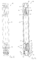
- a magnetometer probe 10 is shown, with the objects that affect the earth's magnetic field or that generate a magnetic field themselves can be.
- the probe 10 has a probe housing 12, in which two inductors 14 and 16 are accommodated.
- the two Inductors 14 and 16 are in the longitudinal direction L of the probe housing 12 viewed axially spaced apart.
- a measuring strip (not shown) added by a not shown Excitation winding is surrounded.
- inductor 14 is pivotable educated.
- the inductor 14 is in one pivotable inductor holder 18 added. Is held the pivotable inductor 14 by two axially spaced apart elastic retaining rings 20 and 21 with which he concentric in one formed in the inductor holder 18 Holding bore 22 is held. The retaining rings 20 and 21 are doing so with great pre-tension on the inner wall of the Holding hole 22 that the inductor 14 in the desired Position in the inductor holder 18 is secured.
- the inductor 14 can also be cast, for example with synthetic resin, held in the inductor holder 18.
- the pivotable inductor holder 18 is pivotably supported in the probe housing 12 by an elastic mounting 24.
- two circumferential grooves 26 and 27 spaced apart from one another are formed on the outer circumference of the essentially hollow cylindrical inductor holder 18.
- an O-ring 28 and 29 made of an elastic material is received in each of the grooves 26 and 27, in each of the grooves 26 and 27, an O-ring 28 and 29 made of an elastic material is received.
- the inductor holder 18 is due to the elastic storage 24 held in the open end of the probe housing 12, wherein the two O-rings 28 and 29 together the inductor holder 18 with the inductor 14 also essentially coaxial hold to the longitudinal axis L of the probe housing 12.
- a radially projecting collar 30 is formed, the purpose of which will be explained later.
- the pivotable inductor holder 18 projects through an adjusting device 32, the one shown in Fig. 2 below End of the probe housing 12 is provided.
- the adjustment device 32 has an adjustment ring 34 which is essentially positioned coaxially to the longitudinal axis L of the probe housing 12 is. In the axial direction is from the adjustment ring 34 a threaded collar 36 with which the adjusting ring 34 in an internal thread 38 provided on the probe housing 12 is screwed in is.
- the threaded collar 36 as be formed smooth collar with which the adjusting ring 34th in the probe housing 12 by casting, for example with Synthetic resin, is secured.
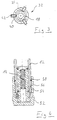
- each threaded bore 40 is a set screw 42 screwed in with her Longitudinal axis radially with respect to the longitudinal axis L of the probe housing 12 runs.
- the trained as grub screws The end faces of adjusting screws 42 are pivotable Inductor holder 18, and hold it in one desired position, as will be explained later.
- the second inductor 16 is identical to that first inductor 14 in a second inductor holder 44 Retaining rings 46 and 47 held.
- the second inductor too can alternatively by casting, for example with Synthetic resin, be secured in the second inductor holder 44.
- the second inductor holder 44 corresponds in shape essentially the swiveling inductor holder 18. However is the outside diameter of the probe housing 12 inserted portion of the second inductor holder 44 dimensioned larger than that of the first inductor holder 18, can but also identical in size to the first inductor holder 18 be formed. Also the second inductor holder 44 is through second O-rings 48 and 49 in the probe housing 12 held defined, the second inductor holder 44 with its inserted into the probe housing 12 End rests on a collar 50 formed in the probe housing 12.
- the second inductor holder 44 is also used the holder rings 46 and 47 and the two O-rings 48 and 49 achieves that the second inductor 16 with respect to the Longitudinal axis L essentially coaxially precise in the probe housing 12 is held.
- the two inductors 14 and 16 must be in one predetermined base distance arranged in the probe housing 12 his.
- the collar 50 facilitates the rotation of the second inductor 16 about the longitudinal axis L of the probe housing 12, the inductor holder 44 after assembly with the collar 50 bears against the end face of the probe housing 12.
- pivotable first inductor 14 relative to the second inductor 16 can be adjusted axially.
- the spatial Location of the measuring strips of the two inductors 14 and 16 see above aligned that the earth field in the inductors 14 and 16 induced voltages are the same.
- the full swing adjustment is then usually done by electrical symmetry of the two inductor windings.
- the two inductors 14 and 16 relative to each other and with respect to the probe housing 12 about the longitudinal axis L of the Probe housing 12 rotated. Then you can adjust it of the various adjusting screws 42 of the adjusting device 32 the swiveling inductor holder 18 in the elastic Storage 24 are moved back and forth. It serves the O-ring 29 near the adjusting device 32 as a resilient Element that has the necessary counter pressure to fix the three set screws 42 are generated while axially spaced from this arranged O-ring 28 as a pivot bearing acts.
- the two inductors 14 and 16 are compared by mutual rotation of the inductors 14 and 16 and by Tilting or swiveling the swiveling inductor 14 in this way, the pivotable inductor 14 and thus its Measuring strips in two perpendicular to each other Directions X and Y that are perpendicular to the same time Longitudinal axis L of the probe housing 12 extend continuously be pivoted.
- caps 52 can be closed. 4 is one such cap 52 shown in section, the is attached to the end of the probe housing 12 into which the pivotable inductor 14 is introduced.
- the closure cap 52 is provided with an internal thread 54, with which the flap 52 on a on the probe housing 12 provided external thread 56 is screwed on.
- the inductors 14 and 16 by inductor holders 18 and 44 in the probe housing 12 held. With an appropriate design of the inductors 14 and 16, however, it is also possible to use such To dispense with inductor holders 18 and 44. Furthermore it is possible to use both inductors 14 and 16 in the previously described Way to make swiveling so that for both Inductors 14 and 16 each have an adjusting device 32 is attached to the probe housing 12.
Landscapes
- Physics & Mathematics (AREA)
- Engineering & Computer Science (AREA)
- General Physics & Mathematics (AREA)
- Remote Sensing (AREA)
- Life Sciences & Earth Sciences (AREA)
- Geology (AREA)
- Environmental & Geological Engineering (AREA)
- General Life Sciences & Earth Sciences (AREA)
- Electromagnetism (AREA)
- Geophysics (AREA)
- Condensed Matter Physics & Semiconductors (AREA)
- Measuring Magnetic Variables (AREA)
- Investigating Or Analyzing Materials By The Use Of Magnetic Means (AREA)
Abstract
Description
- Fig. 1
- eine Seitenansicht einer erfindungsgemäßen Magnetometersonde;
- Fig. 2
- eine Schnittansicht in Längsrichtung der Magnetometersonde nach Fig. 1;
- Fig. 3
- eine Schnittansicht entlang der Schnittlinie A-A in Fig. 2 durch die erfindungsgemäße Magnetometersonde und
- Fig. 4
- einen Ausschnitt der in Fig. 2 gezeigten Schnittansicht der erfindungsgemäßen Magnetometersonde mit aufgeschraubter Verschlusskappe.
In der Nut 26 bzw. 27 ist jeweils ein O-Ring 28 bzw. 29 aus einem elastischen Material aufgenommen.
Claims (16)
- Magnetometersonde mit einem rohrförmigen Sondengehäuse (12) und zwei im Wesentlichen koaxial zur Längsachse (L) des Sondengehäuses (12) in diesem voneinander beabstandet angeordneten Induktoren (14, 16), wobei zumindest einer der Induktoren (14) bezüglich der Längsachse (L) des Sondengehäuses (12) in diesem schwenkbar gelagert und in seiner Schwenkposition arretierbar ist,
dadurch gekennzeichnet, dass der schwenkbare Induktor (14) durch eine elastische Lagerung (24) um zwei rechtwinklig zur Längsachse (L) des Sondengehäuses (12) und rechtwinklig zueinander verlaufende Richtungen (X, Y) schwenkbar gelagert ist. - Magnetometersonde nach Anspruch 1,
dadurch gekennzeichnet, dass der schwenkbare Induktor (14) in einem Induktorhalter (18) aufgenommen ist, mit dem der schwenkbare Induktor (14) in der elastischen Lagerung (24) gelagert ist. - Magnetometersonde nach Anspruch 1 oder 2,
dadurch gekennzeichnet, dass die elastische Lagerung (24) aus mindestens zwei axial voneinander beabstandeten elastischen Elementen (28, 29) gebildet ist, die den schwenkbaren Induktor (14) oder den Induktorhalter (18) im Sondengehäuse (12) schwenkbar lagern. - Magnetometersonde nach Anspruch 3,
dass die beiden elastischen Elemente zwei Ringe (28, 29) aus einem elastischen Material, insbesondere O-Ringe sind. - Magnetometersonde nach Anspruch 4,
dadurch gekennzeichnet, dass die beiden elastischen Ringe (28, 29) auf den Induktor (14) oder auf den Induktorhalter (18) aufgeschoben sind, unter Vorspannung an der Innenwand des Sondengehäuses (12) anliegen und den Induktor (14) oder den Induktorhalter (18) mit Abstand zur Innenwand des Sondengehäuses (12) in diesem halten. - Magnetometersonde nach Anspruch 4 oder 5,
dadurch gekennzeichnet, dass jeder elastische Ring (28, 29) in einer Nut (26, 27) am Induktor (14) oder am Induktorhalter (18) aufgenommen ist. - Magnetometersonde nach einem der vorhergehenden Ansprüche,
dadurch gekennzeichnet, dass am Sondengehäuse (12) eine Justiervorrichtung (32) vorgesehen ist, welche den schwenkbaren Induktor (14) oder den Induktorhalter (18) in seiner eingestellten Schwenkposition hält. - Magnetometersonde nach Anspruch 7,
dadurch gekennzeichnet,dass die Justiervorrichtung (32) einen konzentrisch zur Längsachse (L) angeordneten Justierring (34) aufweist, der am Sondengehäuse (12) befestigt ist und durch den der Induktor (14) oder der Induktorhalter (18) teilweise ragt, unddass gleichmäßig über den Umfang des Justierrings (34) verteilt mindestens drei bezüglich der Längsachse (L) des Sondengehäuses (12) radial verstellbare Stellelemente, insbesondere drei Stellschrauben (42), vorgesehen sind, die den schwenkbaren Induktor (14) oder den schwenkbaren Induktorhalter (18) in der eingestellten Schwenkposition bezüglich der Längsachse (L) halten. - Magnetometersonde nach Anspruch 8,
dadurch gekennzeichnet,dass der Justierring (34) an dem Ende des Sondengehäuses (12), an dem der schwenkbare Induktor (14) vorgesehen ist, befestigt ist unddass die elastische Lagerung (24) unmittelbar benachbart zum Justierring (34) im Sondengehäuse (12) angeordnet ist. - Magnetometersonde nach einem der vorhergehenden Ansprüche,
dadurch gekennzeichnet, dass der schwenkbare Induktor (14) und/oder der zweite Induktor (16) um die Längsachse (L) des Sondengehäuses (12) verdrehbar sind bzw. ist. - Magnetometersonde nach einem der vorhergehenden Ansprüche,
dadurch gekennzeichnet, dass der zweite Induktor (16) in einem zweiten Induktorhalter (44) aufgenommen und durch diesen im Sondengehäuse (12) gehalten ist. - Magnetometersonde nach einem der Ansprüche 2 bis 11,
dadurch gekennzeichnet, dass der Induktor (14, 16) oder die Induktoren (14, 16) jeweils durch elastische Elemente (20, 21, 46, 47), welche auf den jeweiligen Induktor (14, 16) aufgeschoben sind, in dem dem jeweiligen Induktor (14, 16) zugeordneten Induktorhalter (18, 44) gehalten ist bzw. sind. - Magnetometersonde nach einem der vorhergehenden Ansprüche,
dadurch gekennzeichnet, dass der zweite Induktor (16) entsprechend dem schwenkbaren Induktor (14) durch eine elastische Lagerung im Sondengehäuse (12) schwenkbar gelagert und in seiner Schwenkposition arretierbar ist. - Magnetometersonde nach Anspruch 13,
dadurch gekennzeichnet, dass die elastische Lagerung des zweiten Induktors (16) entsprechend einem der Ansprüche 3 bis 6 und, sofern vorgesehen, die Justiervorrichtung des zweiten Induktors (16) entsprechend einem der Ansprüche 7 bis 9 ausgebildet ist. - Magnetometersonde nach einem der Anprüche 1 bis 14,
dadurch gekennzeichnet, dass das Sondengehäuse (12) nach außen hin fluiddicht abgedichtet ist. - Magnetometersonde nach Anspruch 15,
dadurch gekennzeichnet, dass zum Abdichten des Sondengehäuses (12) an diesem Verschlusskappen (50) vorgesehen sind, die die beiden offenen Enden, in die die Induktoren (14, 16) eingesetzt sind, verschließen.
Applications Claiming Priority (2)
| Application Number | Priority Date | Filing Date | Title |
|---|---|---|---|
| DE20118655U | 2001-11-15 | ||
| DE20118655U DE20118655U1 (de) | 2001-11-15 | 2001-11-15 | Magnetometersonde |
Publications (2)
| Publication Number | Publication Date |
|---|---|
| EP1312934A2 true EP1312934A2 (de) | 2003-05-21 |
| EP1312934A3 EP1312934A3 (de) | 2009-12-02 |
Family
ID=7964056
Family Applications (1)
| Application Number | Title | Priority Date | Filing Date |
|---|---|---|---|
| EP02023614A Withdrawn EP1312934A3 (de) | 2001-11-15 | 2002-10-17 | Magnetometersonde |
Country Status (2)
| Country | Link |
|---|---|
| EP (1) | EP1312934A3 (de) |
| DE (1) | DE20118655U1 (de) |
Families Citing this family (2)
| Publication number | Priority date | Publication date | Assignee | Title |
|---|---|---|---|---|
| DE10248891A1 (de) * | 2002-10-18 | 2004-04-29 | MDS Medical Device Solutions AG | Sonde |
| DE102004059199A1 (de) † | 2004-07-02 | 2006-02-09 | OKM Ortungstechnik Krauß & Müller GmbH | Anordnung zum Betreiben eines geophysikalischen Ortungsgeräts |
Family Cites Families (4)
| Publication number | Priority date | Publication date | Assignee | Title |
|---|---|---|---|---|
| US3281660A (en) * | 1964-05-28 | 1966-10-25 | David K Studenick | Locator for magnetic and conducting materials including means for adjusting the relative positions of a pair of sensing coils |
| GB1445063A (en) * | 1974-02-22 | 1976-08-04 | Foerster F | Magnetic gradient detector |
| DE2525751C2 (de) * | 1975-06-10 | 1977-06-16 | Foerster Inst Dr Friedrich | Verstelleinrichtung fuer magnetsonde |
| DE4232466A1 (de) * | 1992-09-28 | 1994-03-31 | Klaus Ebinger | Magnetometersonde |
-
2001
- 2001-11-15 DE DE20118655U patent/DE20118655U1/de not_active Expired - Lifetime
-
2002
- 2002-10-17 EP EP02023614A patent/EP1312934A3/de not_active Withdrawn
Also Published As
| Publication number | Publication date |
|---|---|
| DE20118655U1 (de) | 2002-01-31 |
| EP1312934A3 (de) | 2009-12-02 |
Similar Documents
| Publication | Publication Date | Title |
|---|---|---|
| CH628143A5 (de) | Vorrichtung zur bestimmung der magnetischen kernresonanz einer zu pruefenden materialprobe. | |
| DE60037555T2 (de) | Abstimmvorrichtung für einen dielektrischen Resonator in einem Hohlraum | |
| DE3613098A1 (de) | Permanentmagnetringanordnung fuer abbildungssysteme mit kernmagnetischer resonanz und verfahren zur verwendung einer derartigen anordnung | |
| DE2551968A1 (de) | Magnetsensor | |
| DE10111672C2 (de) | Vorrichtung zur genauen Zentrierung eines NMR-Probengläschens | |
| EP1371996A2 (de) | Vorrichtung zur Positionierung eines länglichen Probenröhrchens relativ zu einem NMR-Empfangsspulensystem | |
| DE2942847C2 (de) | Magnetfelddifferenzsonde | |
| EP1312934A2 (de) | Magnetometersonde | |
| DE2113690C3 (de) | Vorrichtung zur Übertragung von Meßwerten aus oder von Steuerimpulsen in Maschinen bzw. Einrichtungen mit relativ zueinander rotierenden Teilen | |
| DE3124255C2 (de) | Magnetisches Sensorgerät | |
| EP0301651B1 (de) | Positioniervorrichtung für einen Messwertaufnehmer | |
| DE3408137C2 (de) | ||
| DE1938722B2 (de) | Kernresonanz-sondensystem | |
| EP0590349B1 (de) | Magnetometersonde | |
| DE2239555C3 (de) | Vorrichtung zur fuehrung von schlitten, traversen oder anderen verstellbaren maschinenteilen an fuehrungssaeulen | |
| DE3843800C1 (de) | ||
| DE2929404C2 (de) | Differenzfeldsonde | |
| DE2331652C3 (de) | Aufnahmevorrichtung für Vorratsrollen, insbesondere KopierpapierroUen in Lichtpausmaschinen | |
| DE2146032A1 (de) | Vorrichtung zum einstellen der magnetkerne von hochleistungsmagneten | |
| DE2335243A1 (de) | Vorrichtung zum messen von spannungen in einem bauteil u.dgl | |
| DE9213051U1 (de) | Magnetometersonde | |
| DE3905533A1 (de) | Halterung fuer eine spinn- oder zwirnspindel | |
| DE202022102912U1 (de) | Magnetring und Geräusch- und/oder Frequenzlogger | |
| EP2315044B1 (de) | Differenzmagnetometersonde | |
| DE3833590A1 (de) | Vorrichtung zum messen des magnetischen feldes von gradientenspulen an einem mr-tomographiegeraet |
Legal Events
| Date | Code | Title | Description |
|---|---|---|---|
| PUAI | Public reference made under article 153(3) epc to a published international application that has entered the european phase |
Free format text: ORIGINAL CODE: 0009012 |
|
| AK | Designated contracting states |
Designated state(s): AT BE BG CH CY CZ DE DK EE ES FI FR GB GR IE IT LI LU MC NL PT SE SK TR |
|
| AX | Request for extension of the european patent |
Extension state: AL LT LV MK RO SI |
|
| PUAL | Search report despatched |
Free format text: ORIGINAL CODE: 0009013 |
|
| AK | Designated contracting states |
Kind code of ref document: A3 Designated state(s): AT BE BG CH CY CZ DE DK EE ES FI FR GB GR IE IT LI LU MC NL PT SE SK TR |
|
| AX | Request for extension of the european patent |
Extension state: AL LT LV MK RO SI |
|
| 17P | Request for examination filed |
Effective date: 20100107 |
|
| 17Q | First examination report despatched |
Effective date: 20100202 |
|
| STAA | Information on the status of an ep patent application or granted ep patent |
Free format text: STATUS: THE APPLICATION HAS BEEN WITHDRAWN |
|
| 18W | Application withdrawn |
Effective date: 20100527 |