EP1312865A1 - Chambre de combustion annulaire de turbine à gaz - Google Patents
Chambre de combustion annulaire de turbine à gaz Download PDFInfo
- Publication number
- EP1312865A1 EP1312865A1 EP01127137A EP01127137A EP1312865A1 EP 1312865 A1 EP1312865 A1 EP 1312865A1 EP 01127137 A EP01127137 A EP 01127137A EP 01127137 A EP01127137 A EP 01127137A EP 1312865 A1 EP1312865 A1 EP 1312865A1
- Authority
- EP
- European Patent Office
- Prior art keywords
- combustion chamber
- liner
- annular combustion
- wall
- chamber according
- Prior art date
- Legal status (The legal status is an assumption and is not a legal conclusion. Google has not performed a legal analysis and makes no representation as to the accuracy of the status listed.)
- Withdrawn
Links
Images


Classifications
-
- F—MECHANICAL ENGINEERING; LIGHTING; HEATING; WEAPONS; BLASTING
- F23—COMBUSTION APPARATUS; COMBUSTION PROCESSES
- F23R—GENERATING COMBUSTION PRODUCTS OF HIGH PRESSURE OR HIGH VELOCITY, e.g. GAS-TURBINE COMBUSTION CHAMBERS
- F23R3/00—Continuous combustion chambers using liquid or gaseous fuel
- F23R3/002—Wall structures
-
- F—MECHANICAL ENGINEERING; LIGHTING; HEATING; WEAPONS; BLASTING
- F23—COMBUSTION APPARATUS; COMBUSTION PROCESSES
- F23R—GENERATING COMBUSTION PRODUCTS OF HIGH PRESSURE OR HIGH VELOCITY, e.g. GAS-TURBINE COMBUSTION CHAMBERS
- F23R3/00—Continuous combustion chambers using liquid or gaseous fuel
- F23R3/42—Continuous combustion chambers using liquid or gaseous fuel characterised by the arrangement or form of the flame tubes or combustion chambers
- F23R3/50—Combustion chambers comprising an annular flame tube within an annular casing
-
- F—MECHANICAL ENGINEERING; LIGHTING; HEATING; WEAPONS; BLASTING
- F23—COMBUSTION APPARATUS; COMBUSTION PROCESSES
- F23R—GENERATING COMBUSTION PRODUCTS OF HIGH PRESSURE OR HIGH VELOCITY, e.g. GAS-TURBINE COMBUSTION CHAMBERS
- F23R3/00—Continuous combustion chambers using liquid or gaseous fuel
- F23R3/42—Continuous combustion chambers using liquid or gaseous fuel characterised by the arrangement or form of the flame tubes or combustion chambers
- F23R3/60—Support structures; Attaching or mounting means
-
- Y—GENERAL TAGGING OF NEW TECHNOLOGICAL DEVELOPMENTS; GENERAL TAGGING OF CROSS-SECTIONAL TECHNOLOGIES SPANNING OVER SEVERAL SECTIONS OF THE IPC; TECHNICAL SUBJECTS COVERED BY FORMER USPC CROSS-REFERENCE ART COLLECTIONS [XRACs] AND DIGESTS
- Y02—TECHNOLOGIES OR APPLICATIONS FOR MITIGATION OR ADAPTATION AGAINST CLIMATE CHANGE
- Y02T—CLIMATE CHANGE MITIGATION TECHNOLOGIES RELATED TO TRANSPORTATION
- Y02T50/00—Aeronautics or air transport
- Y02T50/60—Efficient propulsion technologies, e.g. for aircraft
Definitions
- the invention relates to an annular combustion chamber for a gas turbine with at least one inlet opening for a burner and an outlet opening into a turbine space.
- the invention also relates to a gas turbine with such an annular combustion chamber.
- Gas turbines are used in addition to generating one Feed force, for example in aircraft, in the Power plant technology widely used.
- a fuel / air mixture is ignited and burns in the combustion chamber.
- the resulting hot combustion gases expand into Direction of a turbine chamber downstream of the combustion chamber, meet an arrangement of guide vanes and Blades and drive the blades and thus the connected to the rotor blades of the turbine.
- the so Mechanical energy obtained can finally, for example be used to generate electricity.
- Annular combustion chambers to which the invention relates, still combustion chamber arrangements with several individual combustion chambers, known as the Cans.
- the present invention relates to at least one, usually several burners, ignited gas mixture introduced into an annular combustion chamber in which it spreads evenly and in an annular stream in the direction of the leading and radially arranged around a rotor shaft Blades of the turbine chamber are flowing.
- the one when burning The resulting high temperatures act on the walls the annular combustion chamber so that it can be used to cool this Walls require special requirements.
- cooling systems also exist Steam, so-called steam cooling, and those with air, so-called Air cooling.
- open cooling systems so-called closed cooling systems.
- open air cooling cooling air is turned on the housing parts to be cooled passed and finally discharged.
- the cooling air can reach the one to be cooled Places to be introduced directly into the combustion chamber together with the hot gas generated during combustion in Direction of the turbine chamber.
- the cooling air can with open cooling, however, also from the turbine housing be led out.
- a problem with open air cooling is that the amount of air required for cooling the total air supply available for the turbine must be removed, with which this portion of the combustion is no longer available. Because on the one hand the overall efficiency of the turbine is reduced, on the other hand a "clean" combustion from an environmental point of view the concept of open air cooling is difficult The concept of closed air cooling explained below inferior.
- Closed air cooling primarily for combustion chambers of the so-called can type is used, uses the for Cooling of the combustion chamber wall used cooling air completely as combustion air. Cooling losses do not occur on, there is no additional need for cooling air.
- Known ring combustion chambers are used for a temperature-resistant construction from the prior art with an inner lining, usually from a variety of temperature-resistant, for example ceramic, elements, provided between the inner lining and the actual annular combustion chamber housing a gap for the passage of the cooling medium is left.
- this structure proves to be complicated because it involves a variety of parts, he is on the other hand because of that between the individual lining segments existing column for training a closed air cooling not suitable.
- the object of the present invention is therefore to provide an annular combustion chamber for a gas turbine of the type mentioned at the outset, which is of simple construction and is suitable for the liner of a closed cooling system.
- annular combustor for a gas turbine with at least one inlet opening for a burner and an opening into a turbine chamber outlet
- the annular combustion chamber an annular space defining the outer wall and disposed in the annular space
- the annular liner for guiding Has hot gas from the at least one inlet opening to the outlet, a gap being left between the liner and the outer wall for the flow of a cooling medium.
- the annular combustion chamber constructed in accordance with the invention stands out through a simple and functional design with a small number of parts.
- Annular combustion chamber designs in which for a double-shell Structure of the ring combustion chamber a lining from a A variety of lining elements typically formed from ceramic is arranged, has the invention Ring combustion chamber instead of the lining a simple liner (a so-called liner) in which the hot gas is guided becomes.
- a simple liner a so-called liner
- the invention is suitable Ring combustion chamber particularly good for the liner of a closed one Air cooling.
- the interior of the liner can be used to cool the liner air completely used to burn the burner are fed.
- the cooling air is preferably in the counterflow principle contrary to the one running inside the liner Hot gas flow led. The during the cooling of the cooling air is absorbed heat by the fact that the cooling air as Combustion air is used, returned to the process, is therefore not lost and contributes to high efficiency the combustion at.
- Liner formed from a thin sheet of metal is formed from a thin sheet of metal.
- Liners results in a material-saving structure
- the thin wall thickness means that the Low temperature gradient across the wall of the liner can be held. This fact makes it possible efficient cooling because of cooling the liner on the outside the ones on the inside of the liner Temperatures can be kept low. Training a low temperature gradient across the wall the liner also leads to comparatively low thermal Tension in the material of the liner and thus contributes a long service life of the liner.
- a simple and inexpensive Structure of such a metal sheet less Strength-formed liners result when this is made from welded together, preferably submerged-arc welded, Ring segments is formed.
- the elastic suspensions are for this purpose preferably by a spring-loaded in the direction of the outer wall, relatively slidable connection between liner and Outer wall formed.
- a spring-loaded in the direction of the outer wall relatively slidable connection between liner and Outer wall formed.
- the elastic suspensions By in the direction of the outer wall directional spring loading exercise the elastic suspensions a permanent pull on the liner, which the liner stabilized in its form.
- the elastic suspensions preferably have a friction damping.
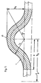
- stiffening structures running in its circumferential direction, preferably stiffening beads.
- the arrangement of the stiffening structures or the elastic Suspensions can vary in the longitudinal direction of the liner Distances, depending on the static or dynamic Stiffening requirements.
- the ring combustion chamber according to the invention is easy to maintain According to an advantageous further development, the Invention provided that the liner and / or the outer wall constructed from at least two axially separated sections is connected to each other along a flange line are. Such an axial separation of the components mentioned enables a to be carried out with comparatively little effort Maintenance. So does not have to disassemble the combustion chamber the entire turbine housing can be opened, the ring combustion chamber segments can after being detached from each other are comparatively easy to remove from the turbine. It is not necessary to remove the rotor.
- this on its inside adjacent to the hot gas to be provided with a thermal barrier coating.
- a thermal barrier coating This can preferably in the form of an atmospheric plasma spray (APS) be applied.
- APS atmospheric plasma spray
- the inside of the liner can be used also protected with a very thin anti-oxidation layer his.
- a piston ring seal of the invention is ideal for Sealing of the outer area through which cooling air flows the interior of the liner in which the hot gas is led.
- the cooling air through an arrangement of through openings directly on the outer surface of the liner, impinges there and creates an intense cooling effect. Because due the speed and temperature distribution of the inside of the liner-guided hot gas flow have different cooling requirements result, it is advantageous if the cooling of the Liners divided according to the cooling requirements Zones are done differently. According to an advantageous development the invention are in the area of an entry zone, in which the hot gas from the burner enters the combustion chamber, in the one left between the outer wall and the liner Space between baffle cooling segments arranged.
- the invention proposes to form these with a small wall thickness and via stiffening structures, preferably stiffening ribs, too stabilize.
- the stiffening ribs preferably run in the circumferential direction.
- a labyrinth seal For sealing the burner bushing through the outer housing is advantageously a labyrinth seal according to the invention proposed.
- a labyrinth seal provides a simple and low leak seal between the in the space between the liner and the outer housing Cooling air and the outside of the outer casing of the ring combustion chamber located within a pressure-tight outer housing Air.
- the invention proposes that the first The turbine guide vanes are fixed to the annular combustion chamber connected is.
- the first is for turbines of conventional design Guide vane row coupled to a guide vane carrier and "pendulum" suspended, because large thermal at this point Difference paths occur.
- the first row of guide blades into the annular combustion chamber the large thermal differential paths at this point avoided.
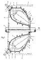
- FIG. 1 is a schematic representation of a longitudinal section by an annular combustion chamber 1 according to the invention and its Position shown in relation to other components of the turbine.
- the annular combustion chamber 1 is in a pressure-resistant outer housing 2 arranged. It is limited by an outer wall 3, in an annular liner 4 is used to guide hot gas is. Remains between the outer wall 3 and the liner 4 a gap 7 for the passage of a cooling medium.
- burner 5 are embedded.
- the burners 5 open into the liner 4, from where the ignited in the burner 5 Hot gases flow-wise in the direction of the burner side opposite ring combustion chamber exit 8.
- a rotor shaft 6 runs along a machine axis MA extends the turbine.
- the annular combustion chamber 1 to the machine axis MA runs at an angle, with the Hot gas flow in the transition area between the ring combustion chamber 1 and the turbine space downstream of this in the direction the machine axis is deflected.
- FIG. 1 is the upper portion of FIG. 1 shown in FIG Sectional view through the annular combustion chamber according to the invention 1 shown.
- the Outer wall 3 constructed from a total of 3 sub-segments, namely an outer segment 31, an inner segment 32 and one Burner passage segment 33.
- the individual segments are connected to one another via flange connections 35 or via Flange connections 36 to the first turbine vane ring 9 connected.
- the liner 4 is also composed of sub-segments, namely an outer segment 41 and an inner segment 42. Both segments are together on a flange 43 connected.
- the liner is in the area of the combustion chamber outlet 8 firmly connected to the outer wall 3 via bolts 44.
- the liner 4 is over in the figure schematically indicated elastic supports with the outer wall 3 relatively slidably connected to this.
- the elastic support 10 can thus differ in thermal expansion on the one hand and for example mechanical movements caused by the gas flows balanced between the outer wall 3 and the liner 4 on the other hand become.
- the entire ring combustor network supports itself on the shaft guard 15.
- a burner 5 passes through the pressure-tight outer housing 2 through an opening in the burner passage segment 33 of the outer wall 3 led and finally flows into the liner 4. Die Carried out through the burner passage segment 33 of the outer wall 3 is sealed by means of a labyrinth seal 51, the entry of the burner 5 into the liner 4 seals one Piston ring seal 52.
- a coating 46 preferably a thermal barrier coating or at least one anti-oxidation layer Mistake.
- a thermal barrier coating can be used as so-called APS (Atmospheric Plasma Spray) can be applied.
- Thermal insulation layers of more durable thickness can be the hot gas side Reduce temperatures by approx. 120 ° C so that the existing heat flow densities on the liner 4 maximum metal temperatures 750 ° C and reasonable thermal stress or lifetime values.
- the baffle cooling segments are designed as metallic hollow boxes. These impingement cooling segments 14 cooling air is supplied separately and they point a shower head-like surface on its surface facing the liner 4 Opening pattern through which cooling air is targeted the surface of the liner 4 is guided in this area.
- the distribution and the diameter of those in the impingement cooling segments 14 trained openings can be particularly thermally stressed in the Inlet zone 11 causes highly efficient cooling become.
- the impingement cooling segments 14 conducted cooling air not distracted by disturbing cross currents, which enables a high impact cooling efficiency.
- a central section 12 adjoins the inlet zone 11 and an outlet zone 13.
- the liner 4 is impact-cooled by means of cooling air directed through the opening arrangement in the outer wall 3 onto the liner 4.
- the outlet zone 13 is also impact-cooled.
- the cooling air flow is divided into two parts, a first part m k1 through the openings formed in the outer wall 3 being used for impingement cooling of the central section 12 or the outlet zone 13, and a second part m k2 directly for the impingement cooling segments 14 is supplied and is used via this for impingement cooling of the inlet zone 11.
- the entire cooling air of the cooling air flows m k1 and m k2 are fed together as cooling air flow m k to the burner and are used there completely as combustion air. In this way, closed air cooling is achieved, which enables the gas turbine to be highly efficient. The heat absorbed by the cooling air is returned to the system, so it is not lost.
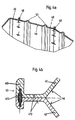
- FIG. 3 is a perspective view of the liner 4 Annular combustion chamber 1 shown. To recognize are here alongside the reinforcing beads running along the circumference 45 starting points 48 for elastic suspensions 10. There are also evenly distributed burner openings 47 can be seen in which the torches arranged in a ring 5 mouth.
- the liner 4 is made up of individual, annular sheet metal segments built up, the welds 49 (Fig. 4a), preferably UP welds are connected to each other. This Construction enables inexpensive and simple manufacture a liner 4 for an annular combustion chamber according to the invention.
- FIG. 4b is a detailed view of the flange 43 for connection of the inner segment 42 and the outer segment 41 of the Liners 4 shown. It can be seen that at this point Inner segment 42 and outer segment 41 meet, the Flange 43 at the end of a slim section in one bead-like stiffening ring 410 ends. This bends you Denting of the outer segment 41 before. Along the narrow area of the flange 43 are those which meet there Inner segment 42 and the outer segment 41 on the outside with a local outer coating 412 to even out the Provide metal temperatures. Inside the stiffening ring 410, which in part through the inner segment 42 to a other part formed by the outer segment 41 of the liner 4 is in a cavity a sealing plate 411 for sealing of the flange 43 used.
- H s is the height of the bead, which in the exemplary embodiment shown is selected to be a bead radius r s .
- the bead spacing designated with b s like the bead width e and the bead height h s, is selected in accordance with the mechanical stiffening requirements; the geometry of the bead can be chosen to vary over the length of the liner 4.
- FIG. 6 is an elastic suspension in detail 10 between the liner 4 and the outer wall 3 shown.
- a tension pin 101 is with a liner point 48 of the liner 4 screwed.
- the tension bolt 101 penetrates the outer wall 3 and protrudes into the outer wall at this point 3 inserted housing 102.
- a Piston 103 used and against the housing 102 by means of Seals 104 sealed.
- a coil spring 105 Between the housing 102 and the Piston 104 uses a coil spring 105.
- the Coil spring exerts one directed away from the housing 102 Compressive force on the piston 103.
- the pull pin 101 is by means of an adjusting nut 106 connected to the piston 103, the surface of the adjusting nut bearing against the piston 103 106 convex, the corresponding surface of the piston 103 is concave. In this way, between the Adjusting nut and the piston 103 formed a ball seat. A counter nut is used to secure the fixing of the draw bolt 107 clamped against the adjusting nut 106. To compensate of relative movements between the liner 4 and the outer wall 3, the piston 103 in the housing 102 in Move the longitudinal direction of the draw bolt 101. By the coil spring 105 is constantly on the draw bolt 101 in the direction the outer wall 3 directed pull, the liner 4 is biased.
- Friction damping element 108 used, which in a corrugated Structure in a direction of extension of the draw bolt 101 extending slot formed in the housing 102 empties. Due to the wave-like design of the friction damping element 108 in this area arise between the housing 102 and the friction damping element 108 in this area high friction forces, the relative movements between the liner 4 and dampen the outer wall 3 and thus the formation of Prevent vibrations. With ⁇ n is a relative thermal expansion of the liner 4 indicated that the elastic Suspensions is compensated.
- annular combustion chamber which is simple and made up of a few parts and that especially for cooling by means of closed air cooling suitable.
Landscapes
- Engineering & Computer Science (AREA)
- Chemical & Material Sciences (AREA)
- Combustion & Propulsion (AREA)
- Mechanical Engineering (AREA)
- General Engineering & Computer Science (AREA)
- Turbine Rotor Nozzle Sealing (AREA)
Priority Applications (5)
| Application Number | Priority Date | Filing Date | Title |
|---|---|---|---|
| EP01127137A EP1312865A1 (fr) | 2001-11-15 | 2001-11-15 | Chambre de combustion annulaire de turbine à gaz |
| PCT/EP2002/012448 WO2003042597A1 (fr) | 2001-11-15 | 2002-11-07 | Chambre de combustion annulaire pour turbine a gaz |
| JP2003544390A JP2005509827A (ja) | 2001-11-15 | 2002-11-07 | ガスタービン用の環状燃焼器 |
| US10/495,832 US20040250549A1 (en) | 2001-11-15 | 2002-11-07 | Annular combustion chamber for a gas turbine |
| EP02802992A EP1446614A1 (fr) | 2001-11-15 | 2002-11-07 | Chambre de combustion annulaire pour turbine a gaz |
Applications Claiming Priority (1)
| Application Number | Priority Date | Filing Date | Title |
|---|---|---|---|
| EP01127137A EP1312865A1 (fr) | 2001-11-15 | 2001-11-15 | Chambre de combustion annulaire de turbine à gaz |
Publications (1)
| Publication Number | Publication Date |
|---|---|
| EP1312865A1 true EP1312865A1 (fr) | 2003-05-21 |
Family
ID=8179243
Family Applications (2)
| Application Number | Title | Priority Date | Filing Date |
|---|---|---|---|
| EP01127137A Withdrawn EP1312865A1 (fr) | 2001-11-15 | 2001-11-15 | Chambre de combustion annulaire de turbine à gaz |
| EP02802992A Withdrawn EP1446614A1 (fr) | 2001-11-15 | 2002-11-07 | Chambre de combustion annulaire pour turbine a gaz |
Family Applications After (1)
| Application Number | Title | Priority Date | Filing Date |
|---|---|---|---|
| EP02802992A Withdrawn EP1446614A1 (fr) | 2001-11-15 | 2002-11-07 | Chambre de combustion annulaire pour turbine a gaz |
Country Status (4)
| Country | Link |
|---|---|
| US (1) | US20040250549A1 (fr) |
| EP (2) | EP1312865A1 (fr) |
| JP (1) | JP2005509827A (fr) |
| WO (1) | WO2003042597A1 (fr) |
Cited By (8)
| Publication number | Priority date | Publication date | Assignee | Title |
|---|---|---|---|---|
| EP1482246A1 (fr) * | 2003-05-30 | 2004-12-01 | Siemens Aktiengesellschaft | Chambre de combustion |
| EP1826491A1 (fr) * | 2006-02-27 | 2007-08-29 | Snecma | Chambre de combustion annulaire à fond amovible |
| EP2031303A1 (fr) * | 2007-08-30 | 2009-03-04 | Snecma | Turbomachine à chambre annulaire de combustion |
| EP2487417A1 (fr) * | 2011-02-09 | 2012-08-15 | Siemens Aktiengesellschaft | Boîtier de chambre de combustion |
| DE102011076473A1 (de) * | 2011-05-25 | 2012-11-29 | Rolls-Royce Deutschland Ltd & Co Kg | Segmentbauteil aus Hochtemperaturgussmaterial für eine Ringbrennkammer, Ringbrennkammer für ein Flugzeugtriebwerk, Flugzeugtriebwerk und Verfahren zur Herstellung einer Ringbrennkammer |
| US8516823B2 (en) | 2007-09-24 | 2013-08-27 | Alstom Technology Ltd. | Gas turbine with welded combustor liners |
| FR2996289A1 (fr) * | 2012-10-01 | 2014-04-04 | Turbomeca | Chambre de combustion comprenant un tube a flamme fixe au moyen de trois elements de centrage. |
| EP3002519A1 (fr) * | 2014-09-30 | 2016-04-06 | ALSTOM Technology Ltd | Agencement de chambre de combustion avec système de fixation pour pièces de chambre de combustion |
Families Citing this family (16)
| Publication number | Priority date | Publication date | Assignee | Title |
|---|---|---|---|---|
| EP1724526A1 (fr) * | 2005-05-13 | 2006-11-22 | Siemens Aktiengesellschaft | Coquille de turbine à gaz, turbine à gaz et procédé de démarrage et d'arrêt d'une turbine à gaz |
| US7493771B2 (en) * | 2005-11-30 | 2009-02-24 | General Electric Company | Methods and apparatuses for assembling a gas turbine engine |
| DE102009035550A1 (de) | 2009-07-31 | 2011-02-03 | Man Diesel & Turbo Se | Gasturbinenbrennkammer |
| US8695352B2 (en) | 2012-07-12 | 2014-04-15 | Solar Turbines Inc. | Baffle assembly for bleed air system of gas turbine engine |
| US20140223919A1 (en) * | 2013-02-14 | 2014-08-14 | United Technologies Corporation | Flexible liner hanger |
| EP3084303B1 (fr) * | 2013-12-19 | 2022-01-26 | Raytheon Technologies Corporation | Réseau de dépressions mécaniques thermiques pour un ensemble paroi de chambre de combustion |
| US9890953B2 (en) * | 2014-01-10 | 2018-02-13 | United Technologies Corporation | Attachment of ceramic matrix composite panel to liner |
| US10281140B2 (en) | 2014-07-15 | 2019-05-07 | Chevron U.S.A. Inc. | Low NOx combustion method and apparatus |
| DE102014226707A1 (de) * | 2014-12-19 | 2016-06-23 | Rolls-Royce Deutschland Ltd & Co Kg | Gasturbinenbrennkammer mit veränderter Wandstärke |
| US10465907B2 (en) * | 2015-09-09 | 2019-11-05 | General Electric Company | System and method having annular flow path architecture |
| EP3252378A1 (fr) * | 2016-05-31 | 2017-12-06 | Siemens Aktiengesellschaft | Agencement de chambre de combustion annulaire de turbine à gaz |
| US20180306120A1 (en) | 2017-04-21 | 2018-10-25 | General Electric Company | Pressure regulated piston seal for a gas turbine combustor liner |
| CN109098860A (zh) * | 2017-06-21 | 2018-12-28 | 杨航 | 一种动力装置 |
| DE102017212575A1 (de) * | 2017-07-21 | 2019-01-24 | Siemens Aktiengesellschaft | Verfahren zur Erhöhung der Leistung einer Gasturbine |
| US10801469B2 (en) * | 2017-11-07 | 2020-10-13 | General Electric Company | Wind blade joints with floating connectors |
| JP2023183452A (ja) * | 2022-06-16 | 2023-12-28 | 川崎重工業株式会社 | ガスタービンの燃焼器 |
Citations (8)
| Publication number | Priority date | Publication date | Assignee | Title |
|---|---|---|---|---|
| US4168609A (en) * | 1977-12-01 | 1979-09-25 | United Technologies Corporation | Folded-over pilot burner |
| US4195475A (en) * | 1977-12-21 | 1980-04-01 | General Motors Corporation | Ring connection for porous combustor wall panels |
| EP0534193A2 (fr) * | 1991-09-23 | 1993-03-31 | Eastman Kodak Company | Procédé de détection d'impression à jet d'encre ou matricielle |
| US5209067A (en) * | 1990-10-17 | 1993-05-11 | Societe Nationale D'etude Et De Construction De Moteurs D'aviation S.N.E.C.M.A. | Gas turbine combustion chamber wall structure for minimizing cooling film disturbances |
| US5329773A (en) * | 1989-08-31 | 1994-07-19 | Alliedsignal Inc. | Turbine combustor cooling system |
| EP0780638A2 (fr) * | 1995-12-20 | 1997-06-25 | Mtu Motoren- Und Turbinen-Union MàNchen Gmbh | Chambre de combustion pour turbine à gaz |
| EP0896193A2 (fr) * | 1997-08-05 | 1999-02-10 | European Gas Turbines Limited | Chambre de combustion pour turbine à gaz |
| WO1999027304A1 (fr) * | 1997-11-19 | 1999-06-03 | Siemens Aktiengesellschaft | Chambre de combustion et procede de refroidissement par vapeur d'une chambre de combustion |
Family Cites Families (79)
| Publication number | Priority date | Publication date | Assignee | Title |
|---|---|---|---|---|
| BE489359A (fr) * | 1944-10-05 | |||
| US3031844A (en) * | 1960-08-12 | 1962-05-01 | William A Tomolonius | Split combustion liner |
| US3169367A (en) * | 1963-07-18 | 1965-02-16 | Westinghouse Electric Corp | Combustion apparatus |
| US3702058A (en) * | 1971-01-13 | 1972-11-07 | Westinghouse Electric Corp | Double wall combustion chamber |
| US4912922A (en) * | 1972-12-19 | 1990-04-03 | General Electric Company | Combustion chamber construction |
| US4555901A (en) * | 1972-12-19 | 1985-12-03 | General Electric Company | Combustion chamber construction |
| US4480436A (en) * | 1972-12-19 | 1984-11-06 | General Electric Company | Combustion chamber construction |
| US3879940A (en) * | 1973-07-30 | 1975-04-29 | Gen Electric | Gas turbine engine fuel delivery tube assembly |
| US3899882A (en) * | 1974-03-27 | 1975-08-19 | Westinghouse Electric Corp | Gas turbine combustor basket cooling |
| US4198815A (en) * | 1975-12-24 | 1980-04-22 | General Electric Company | Central injection fuel carburetor |
| US4151713A (en) * | 1977-03-15 | 1979-05-01 | United Technologies Corporation | Burner for gas turbine engine |
| US4112676A (en) * | 1977-04-05 | 1978-09-12 | Westinghouse Electric Corp. | Hybrid combustor with staged injection of pre-mixed fuel |
| CH633347A5 (de) * | 1978-08-03 | 1982-11-30 | Bbc Brown Boveri & Cie | Gasturbine. |
| JPS5554636A (en) * | 1978-10-16 | 1980-04-22 | Hitachi Ltd | Combustor of gas turbine |
| GB2044912B (en) * | 1979-03-22 | 1983-02-23 | Rolls Royce | Gas turbine combustion chamber |
| US4232527A (en) * | 1979-04-13 | 1980-11-11 | General Motors Corporation | Combustor liner joints |
| JPS56124834A (en) * | 1980-03-05 | 1981-09-30 | Hitachi Ltd | Gas-turbine combustor |
| GB2087065B (en) * | 1980-11-08 | 1984-11-07 | Rolls Royce | Wall structure for a combustion chamber |
| US4413477A (en) * | 1980-12-29 | 1983-11-08 | General Electric Company | Liner assembly for gas turbine combustor |
| US4819438A (en) * | 1982-12-23 | 1989-04-11 | United States Of America | Steam cooled rich-burn combustor liner |
| US4466239A (en) * | 1983-02-22 | 1984-08-21 | General Electric Company | Gas turbine engine with improved air cooling circuit |
| JPS59229114A (ja) * | 1983-06-08 | 1984-12-22 | Hitachi Ltd | ガスタ−ビン用燃焼器 |
| US4719748A (en) * | 1985-05-14 | 1988-01-19 | General Electric Company | Impingement cooled transition duct |
| FR2599821B1 (fr) * | 1986-06-04 | 1988-09-02 | Snecma | Chambre de combustion pour turbomachines a orifices de melange assurant le positionnement de la paroi chaude sur la paroi froide |
| US4815272A (en) * | 1987-05-05 | 1989-03-28 | United Technologies Corporation | Turbine cooling and thermal control |
| FR2624953B1 (fr) * | 1987-12-16 | 1990-04-20 | Snecma | Chambre de combustion, pour turbomachines, possedant un convergent a doubles parois |
| US5083422A (en) * | 1988-03-25 | 1992-01-28 | General Electric Company | Method of breach cooling |
| US4944151A (en) * | 1988-09-26 | 1990-07-31 | Avco Corporation | Segmented combustor panel |
| US5003773A (en) * | 1989-06-23 | 1991-04-02 | United Technologies Corporation | Bypass conduit for gas turbine engine |
| US5174108A (en) * | 1989-12-11 | 1992-12-29 | Sundstrand Corporation | Turbine engine combustor without air film cooling |
| FR2661714B1 (fr) * | 1990-05-03 | 1994-06-17 | Snecma | Dispositif d'alimentation en comburant d'une turbine a gaz. |
| GB9018014D0 (en) * | 1990-08-16 | 1990-10-03 | Rolls Royce Plc | Gas turbine engine combustor |
| GB9018013D0 (en) * | 1990-08-16 | 1990-10-03 | Rolls Royce Plc | Gas turbine engine combustor |
| GB2247522B (en) * | 1990-09-01 | 1993-11-10 | Rolls Royce Plc | Gas turbine engine combustor |
| US5181377A (en) * | 1991-04-16 | 1993-01-26 | General Electric Company | Damped combustor cowl structure |
| FR2679010B1 (fr) * | 1991-07-10 | 1993-09-24 | Snecma | Chambre de combustion de turbomachine a bols de prevaporisation demontables. |
| CA2089272C (fr) * | 1992-03-23 | 2002-09-03 | James Norman Reinhold, Jr. | Chambre de combustion presentant une resistance aux chocs |
| US5237813A (en) * | 1992-08-21 | 1993-08-24 | Allied-Signal Inc. | Annular combustor with outer transition liner cooling |
| US5335502A (en) * | 1992-09-09 | 1994-08-09 | General Electric Company | Arched combustor |
| IT1255613B (it) * | 1992-09-24 | 1995-11-09 | Eniricerche Spa | Sistema di combustione a basse emissioni inquinanti per turbine a gas |
| US5363643A (en) * | 1993-02-08 | 1994-11-15 | General Electric Company | Segmented combustor |
| FR2710968B1 (fr) * | 1993-10-06 | 1995-11-03 | Snecma | Chambre de combustion à double paroi. |
| US5461866A (en) * | 1994-12-15 | 1995-10-31 | United Technologies Corporation | Gas turbine engine combustion liner float wall cooling arrangement |
| US5924288A (en) * | 1994-12-22 | 1999-07-20 | General Electric Company | One-piece combustor cowl |
| US5704208A (en) * | 1995-12-05 | 1998-01-06 | Brewer; Keith S. | Serviceable liner for gas turbine engine |
| US5974805A (en) * | 1997-10-28 | 1999-11-02 | Rolls-Royce Plc | Heat shielding for a turbine combustor |
| JP4172913B2 (ja) * | 1998-03-19 | 2008-10-29 | シーメンス アクチエンゲゼルシヤフト | 燃焼器用壁セグメントおよび燃焼器 |
| US6098397A (en) * | 1998-06-08 | 2000-08-08 | Caterpillar Inc. | Combustor for a low-emissions gas turbine engine |
| US6260359B1 (en) * | 1999-11-01 | 2001-07-17 | General Electric Company | Offset dilution combustor liner |
| US6438958B1 (en) * | 2000-02-28 | 2002-08-27 | General Electric Company | Apparatus for reducing heat load in combustor panels |
| US6497104B1 (en) * | 2000-10-30 | 2002-12-24 | General Electric Company | Damped combustion cowl structure |
| US6526756B2 (en) * | 2001-02-14 | 2003-03-04 | General Electric Company | Method and apparatus for enhancing heat transfer in a combustor liner for a gas turbine |
| US6606861B2 (en) * | 2001-02-26 | 2003-08-19 | United Technologies Corporation | Low emissions combustor for a gas turbine engine |
| US6449952B1 (en) * | 2001-04-17 | 2002-09-17 | General Electric Company | Removable cowl for gas turbine combustor |
| US6530227B1 (en) * | 2001-04-27 | 2003-03-11 | General Electric Co. | Methods and apparatus for cooling gas turbine engine combustors |
| JP2004524479A (ja) * | 2001-04-27 | 2004-08-12 | シーメンス アクチエンゲゼルシヤフト | 特にガスタービンの燃焼室 |
| US6675582B2 (en) * | 2001-05-23 | 2004-01-13 | General Electric Company | Slot cooled combustor line |
| FR2825787B1 (fr) * | 2001-06-06 | 2004-08-27 | Snecma Moteurs | Montage de chambre de combustion cmc de turbomachine par viroles de liaison souples |
| FR2825783B1 (fr) * | 2001-06-06 | 2003-11-07 | Snecma Moteurs | Accrochage de chambre de combustion cmc de turbomachine par pattes brasees |
| FR2825784B1 (fr) * | 2001-06-06 | 2003-08-29 | Snecma Moteurs | Accrochage de chambre de combustion cmc de turbomachine utilisant les trous de dilution |
| US6513331B1 (en) * | 2001-08-21 | 2003-02-04 | General Electric Company | Preferential multihole combustor liner |
| US6530225B1 (en) * | 2001-09-21 | 2003-03-11 | Honeywell International, Inc. | Waffle cooling |
| US6735956B2 (en) * | 2001-10-26 | 2004-05-18 | Pratt & Whitney Canada Corp. | High pressure turbine blade cooling scoop |
| US6701714B2 (en) * | 2001-12-05 | 2004-03-09 | United Technologies Corporation | Gas turbine combustor |
| US6640546B2 (en) * | 2001-12-20 | 2003-11-04 | General Electric Company | Foil formed cooling area enhancement |
| US6651437B2 (en) * | 2001-12-21 | 2003-11-25 | General Electric Company | Combustor liner and method for making thereof |
| GB2384046B (en) * | 2002-01-15 | 2005-07-06 | Rolls Royce Plc | A double wall combuster tile arrangement |
| US6865889B2 (en) * | 2002-02-01 | 2005-03-15 | General Electric Company | Method and apparatus to decrease combustor emissions |
| US6715279B2 (en) * | 2002-03-04 | 2004-04-06 | General Electric Company | Apparatus for positioning an igniter within a liner port of a gas turbine engine |
| US6655147B2 (en) * | 2002-04-10 | 2003-12-02 | General Electric Company | Annular one-piece corrugated liner for combustor of a gas turbine engine |
| US6751961B2 (en) * | 2002-05-14 | 2004-06-22 | United Technologies Corporation | Bulkhead panel for use in a combustion chamber of a gas turbine engine |
| US6834505B2 (en) * | 2002-10-07 | 2004-12-28 | General Electric Company | Hybrid swirler |
| US6826913B2 (en) * | 2002-10-31 | 2004-12-07 | Honeywell International Inc. | Airflow modulation technique for low emissions combustors |
| US7003959B2 (en) * | 2002-12-31 | 2006-02-28 | General Electric Company | High temperature splash plate for temperature reduction by optical reflection and process for manufacturing |
| US6925811B2 (en) * | 2002-12-31 | 2005-08-09 | General Electric Company | High temperature combustor wall for temperature reduction by optical reflection and process for manufacturing |
| US6986253B2 (en) * | 2003-07-16 | 2006-01-17 | General Electric Company | Methods and apparatus for cooling gas turbine engine combustors |
| US6976363B2 (en) * | 2003-08-11 | 2005-12-20 | General Electric Company | Combustor dome assembly of a gas turbine engine having a contoured swirler |
| US7043921B2 (en) * | 2003-08-26 | 2006-05-16 | Honeywell International, Inc. | Tube cooled combustor |
| US7007481B2 (en) * | 2003-09-10 | 2006-03-07 | General Electric Company | Thick coated combustor liner |
-
2001
- 2001-11-15 EP EP01127137A patent/EP1312865A1/fr not_active Withdrawn
-
2002
- 2002-11-07 JP JP2003544390A patent/JP2005509827A/ja not_active Abandoned
- 2002-11-07 US US10/495,832 patent/US20040250549A1/en not_active Abandoned
- 2002-11-07 WO PCT/EP2002/012448 patent/WO2003042597A1/fr active Application Filing
- 2002-11-07 EP EP02802992A patent/EP1446614A1/fr not_active Withdrawn
Patent Citations (8)
| Publication number | Priority date | Publication date | Assignee | Title |
|---|---|---|---|---|
| US4168609A (en) * | 1977-12-01 | 1979-09-25 | United Technologies Corporation | Folded-over pilot burner |
| US4195475A (en) * | 1977-12-21 | 1980-04-01 | General Motors Corporation | Ring connection for porous combustor wall panels |
| US5329773A (en) * | 1989-08-31 | 1994-07-19 | Alliedsignal Inc. | Turbine combustor cooling system |
| US5209067A (en) * | 1990-10-17 | 1993-05-11 | Societe Nationale D'etude Et De Construction De Moteurs D'aviation S.N.E.C.M.A. | Gas turbine combustion chamber wall structure for minimizing cooling film disturbances |
| EP0534193A2 (fr) * | 1991-09-23 | 1993-03-31 | Eastman Kodak Company | Procédé de détection d'impression à jet d'encre ou matricielle |
| EP0780638A2 (fr) * | 1995-12-20 | 1997-06-25 | Mtu Motoren- Und Turbinen-Union MàNchen Gmbh | Chambre de combustion pour turbine à gaz |
| EP0896193A2 (fr) * | 1997-08-05 | 1999-02-10 | European Gas Turbines Limited | Chambre de combustion pour turbine à gaz |
| WO1999027304A1 (fr) * | 1997-11-19 | 1999-06-03 | Siemens Aktiengesellschaft | Chambre de combustion et procede de refroidissement par vapeur d'une chambre de combustion |
Cited By (18)
| Publication number | Priority date | Publication date | Assignee | Title |
|---|---|---|---|---|
| WO2004106809A1 (fr) * | 2003-05-30 | 2004-12-09 | Siemens Aktiengesellschaft | Chambre a combustion |
| EP1482246A1 (fr) * | 2003-05-30 | 2004-12-01 | Siemens Aktiengesellschaft | Chambre de combustion |
| US8245513B2 (en) | 2003-05-30 | 2012-08-21 | Siemens Aktiengesellschaft | Combustion chamber |
| EP1826491A1 (fr) * | 2006-02-27 | 2007-08-29 | Snecma | Chambre de combustion annulaire à fond amovible |
| FR2897923A1 (fr) * | 2006-02-27 | 2007-08-31 | Snecma Sa | Chambre de combustion annulaire a fond amovible |
| US7854126B2 (en) | 2006-02-27 | 2010-12-21 | Snecma | Annular combustion chamber with a removable end wall |
| EP2031303A1 (fr) * | 2007-08-30 | 2009-03-04 | Snecma | Turbomachine à chambre annulaire de combustion |
| FR2920524A1 (fr) * | 2007-08-30 | 2009-03-06 | Snecma Sa | Turbomachine a chambre annulaire de combustion |
| US7661273B2 (en) | 2007-08-30 | 2010-02-16 | Snecma | Turbomachine with annular combustion chamber |
| US8516823B2 (en) | 2007-09-24 | 2013-08-27 | Alstom Technology Ltd. | Gas turbine with welded combustor liners |
| EP2487417A1 (fr) * | 2011-02-09 | 2012-08-15 | Siemens Aktiengesellschaft | Boîtier de chambre de combustion |
| RU2583327C2 (ru) * | 2011-02-09 | 2016-05-10 | Сименс Акциенгезелльшафт | Корпус камеры сгорания |
| DE102011076473A1 (de) * | 2011-05-25 | 2012-11-29 | Rolls-Royce Deutschland Ltd & Co Kg | Segmentbauteil aus Hochtemperaturgussmaterial für eine Ringbrennkammer, Ringbrennkammer für ein Flugzeugtriebwerk, Flugzeugtriebwerk und Verfahren zur Herstellung einer Ringbrennkammer |
| US8646279B2 (en) | 2011-05-25 | 2014-02-11 | Rolls-Royce Deutschland Ltd & Co Kg | Segment component in high-temperature casting material for an annular combustion chamber, annular combustion chamber for an aircraft engine, aircraft engine and method for the manufacture of an annular combustion chamber |
| FR2996289A1 (fr) * | 2012-10-01 | 2014-04-04 | Turbomeca | Chambre de combustion comprenant un tube a flamme fixe au moyen de trois elements de centrage. |
| WO2014053728A1 (fr) * | 2012-10-01 | 2014-04-10 | Turbomeca | Chambre de combustion comprenant un tube à flamme fixé au moyen de trois éléments de centrage |
| EP3002519A1 (fr) * | 2014-09-30 | 2016-04-06 | ALSTOM Technology Ltd | Agencement de chambre de combustion avec système de fixation pour pièces de chambre de combustion |
| US10151489B2 (en) | 2014-09-30 | 2018-12-11 | Ansaldo Energia Switzerland AG | Combustor arrangement with fastening system for combustor parts |
Also Published As
| Publication number | Publication date |
|---|---|
| WO2003042597A1 (fr) | 2003-05-22 |
| EP1446614A1 (fr) | 2004-08-18 |
| JP2005509827A (ja) | 2005-04-14 |
| US20040250549A1 (en) | 2004-12-16 |
Similar Documents
| Publication | Publication Date | Title |
|---|---|---|
| EP1312865A1 (fr) | Chambre de combustion annulaire de turbine à gaz | |
| EP1636526B1 (fr) | Chambre a combustion | |
| DE69818376T2 (de) | Gasturbinenbrennkammer | |
| DE602005001682T2 (de) | Helmholtzresonator für eine Brennkammer eines Gasturbinentriebwerks | |
| DE2907769C2 (de) | Turbinenschaufel-Mantelhalterung | |
| EP1182398B1 (fr) | Procédé pour accroítre la stabilité fluidique d'un brûleur de prémélange ainsi que brûleur de prémélange pour mettre en oeuvre le procédé | |
| DE2012949A1 (de) | Wandkonstruktion und Luftzufuhrlöcher für ein Gasturbinentriebwerk | |
| DE874680C (de) | Duesenkasten fuer Gasturbinentriebwerke | |
| EP2340397B1 (fr) | Pièce du brûleur pour une chambre de combustion d'une turbine à gaz et turbine à gaz | |
| DE112007002152T5 (de) | Prallplattenkuppelanordnung für einen Turbinenmotor | |
| CH697920A2 (de) | Turbinentriebwerk mit einer Brennkammerauskleidung mit wirbelluftgekühltem hinterem Ende und Kühlverfahren. | |
| DE102005025823A1 (de) | Verfahren und Vorrichtung zum Kühlen einer Brennkammerauskleidung und eines Übergangsteils einer Gasturbine | |
| DE3200972A1 (de) | Brennereinsatz, insbesondere fuer ein gasturbinentriebwerk | |
| EP1865259A2 (fr) | Paroi de chambre de combustion de turbine à gaz pour une chambre de turbine à gaz à combustion pauvre | |
| DE1953047A1 (de) | Gas- oder Dampfturbine der Axialbauart fuer hohe Arbeitsmitteltemperaturen | |
| EP1904717B1 (fr) | Element de carter conducteur de gaz chaud, enveloppe de protection d'arbre et systeme de turbine a gaz | |
| EP2184445A1 (fr) | Support d'aubes statorique axialement segmenté d'une turbine à gaz | |
| DE2414376A1 (de) | Kuehlschlitzanordnung fuer einen brennkammereinsatz | |
| DE4446611A1 (de) | Brennkammer | |
| EP1724526A1 (fr) | Coquille de turbine à gaz, turbine à gaz et procédé de démarrage et d'arrêt d'une turbine à gaz | |
| DE60122619T2 (de) | Gasturbinenbrennkammerwand | |
| EP2409086B1 (fr) | Arrangement de brûleur pour une turbine à gaz | |
| EP2347100B1 (fr) | Turbine à gaz avec insert de refroidissement | |
| EP1588102B1 (fr) | Element de bouclier thermique, chambre de combustion et turbine a gaz | |
| DE102016212649A1 (de) | Brennerdichtung einer Gasturbine und Verfahren zu deren Herstellung |
Legal Events
| Date | Code | Title | Description |
|---|---|---|---|
| PUAI | Public reference made under article 153(3) epc to a published international application that has entered the european phase |
Free format text: ORIGINAL CODE: 0009012 |
|
| AK | Designated contracting states |
Designated state(s): AT BE CH CY DE DK ES FI FR GB GR IE IT LI LU MC NL PT SE TR |
|
| AX | Request for extension of the european patent |
Extension state: AL LT LV MK RO SI |
|
| AKX | Designation fees paid | ||
| REG | Reference to a national code |
Ref country code: DE Ref legal event code: 8566 |
|
| STAA | Information on the status of an ep patent application or granted ep patent |
Free format text: STATUS: THE APPLICATION IS DEEMED TO BE WITHDRAWN |
|
| 18D | Application deemed to be withdrawn |
Effective date: 20031122 |