EP1312803A2 - Automatische Pumpe - Google Patents
Automatische Pumpe Download PDFInfo
- Publication number
- EP1312803A2 EP1312803A2 EP02016058A EP02016058A EP1312803A2 EP 1312803 A2 EP1312803 A2 EP 1312803A2 EP 02016058 A EP02016058 A EP 02016058A EP 02016058 A EP02016058 A EP 02016058A EP 1312803 A2 EP1312803 A2 EP 1312803A2
- Authority
- EP
- European Patent Office
- Prior art keywords
- valve
- inclined surface
- automatic pump
- housing
- fluid
- Prior art date
- Legal status (The legal status is an assumption and is not a legal conclusion. Google has not performed a legal analysis and makes no representation as to the accuracy of the status listed.)
- Granted
Links
Images


Classifications
-
- F—MECHANICAL ENGINEERING; LIGHTING; HEATING; WEAPONS; BLASTING
- F04—POSITIVE - DISPLACEMENT MACHINES FOR LIQUIDS; PUMPS FOR LIQUIDS OR ELASTIC FLUIDS
- F04D—NON-POSITIVE-DISPLACEMENT PUMPS
- F04D15/00—Control, e.g. regulation, of pumps, pumping installations or systems
- F04D15/0005—Control, e.g. regulation, of pumps, pumping installations or systems by using valves
- F04D15/0022—Control, e.g. regulation, of pumps, pumping installations or systems by using valves throttling valves or valves varying the pump inlet opening or the outlet opening
-
- F—MECHANICAL ENGINEERING; LIGHTING; HEATING; WEAPONS; BLASTING
- F04—POSITIVE - DISPLACEMENT MACHINES FOR LIQUIDS; PUMPS FOR LIQUIDS OR ELASTIC FLUIDS
- F04D—NON-POSITIVE-DISPLACEMENT PUMPS
- F04D29/00—Details, component parts, or accessories
- F04D29/40—Casings; Connections of working fluid
- F04D29/42—Casings; Connections of working fluid for radial or helico-centrifugal pumps
Definitions
- the present invention relates to an automatic pump, especially an automatic pump with an improved Valve construction that has a fluid channel in a pump can open / close and at the same time the pump depending on Can switch on / off the presence of a fluid flow in the fluid channel.
- a pump is an apparatus for transporting fluid through the company of an engine. Especially with an automatic pump, the Flow of the fluid automatically controlled. Below is below 1, a conventional automatic pump described.
- Fig. 1 is a partially cutaway side view of a conventional automatic pump, the schematic of which Construction shows.
- a pump comprises a housing 10, which includes an impeller 11 and in which a fluid channel is formed.
- the fluid channel in the housing 10 is with an inlet pipe 13a and Outlet pipe 13b connected through which fluid is sucked or is expelled.
- the impeller 11 is rotated by a motor 15 and causes the suction of the fluid through the inlet pipe 13a and ejecting the fluid through the outlet pipe 13b.
- a valve 21 is arranged on one end of the fluid channel of the housing 10 on the side of the Outlet pipe 13b .
- valve 21 The function of the valve 21 is described below.
- valve 21 In the conventional automatic pump, the one described above Construction, the valve 21 must be in the upright position, since that Valve 21 is lowered by its own weight. So that is necessarily a restriction of direction when installing the conventional automatic pump connected.
- the present invention aims to: aforementioned problems associated with the prior art are to be solved, and an object of the present invention is automatic pump that can be installed regardless of the direction.
- a pump comprising: a metal housing in which a fluid channel is provided a first end and a second end is formed, the first end is connected to an inlet pipe which is connected to a Water source is connected, and the second end to one Outlet pipe is connected, which with a consumer side is connected, and wherein the housing is a control unit on one side of the housing; an impeller arranged in the housing, which Draws fluid through the inlet pipe and ejects it through the outlet pipe; a motor located outside the housing, the impeller rotates according to the control unit; a leader who at a portion of the fluid channel of the housing near the Outlet pipe is arranged; a valve in which the guide member so is used that the guide member in the linear direction by the Valve can be moved back and forth, the valve being a first End side, which acts on the pressure in the inlet pipe, and a second End side, which acts on pressure in the outlet pipe, and the valve through the pressure difference between the inlet pipe and the outlet pipe linearly moving
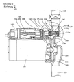
- FIG. 2 is a partially cutaway side view of a automatic pump according to a preferred embodiment of the present invention schematically showing its construction;
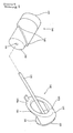
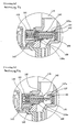
- FIG. 3 is an exploded view of a Guide member and a valve in the automatic pump Fig. 2 are used; 4a and 4b are enlarged Representations of a cross section of a valve to illustrate the Function of the automatic pump from Fig. 2;
- an automatic pump 100 includes after the present embodiment, a housing 110 made of a magnetic conductive material such as metal in which a fluid channel 111 is formed.
- a housing 110 made of a magnetic conductive material such as metal in which a fluid channel 111 is formed.
- One end of the fluid channel 111 of the housing 110 is connected to one Inlet pipe 113 connected, which is connected to a water source while the other end of the fluid channel 111 of the housing 110 is connected to an outlet pipe 115, which with a Consumer side is connected.
- Impeller 121 is arranged, and outside of the housing 110 is a Motor 125 arranged for rotating the impeller 121. The impeller 121 sucks fluid through the inlet tube 113 and pushes it through the Exhaust pipe 115 out.
- a seat recess 117 At a portion of the fluid channel 111 of the housing 110 in the Near the outlet pipe 115 is a seat recess 117 with a step 117a, and in a portion of the housing 110 opposite a valve actuation opening 119 is formed in the seat recess 117.
- the valve actuation opening 119 is preferably in the direction of the Motor 125 and an outer cover 160 aligned, which later is described in more detail.
- a guide member 130 comprising one, is seated in the seat recess 117 Base 131, a foot 133, a guide rod 135, a contact piece 137 and a contact ring 139.
- the base is disc-shaped and is in step 117a of seat recess 117 is inserted, and foot 133 extends from a surface of the base 131 so that it is at a Bottom surface 117b of the seat recess 117 abuts. It extends further the guide rod 135 from a middle portion of the other Area of the base 131 through the valve operating opening 119, and that Contact piece 137 extends from an upper half of a circumference the other surface of the base 131. This means that the contact piece 137 has a semi-cylindrical shape.
- the first is sloping Surface 137a of contact piece 137 at a predetermined distance of the base 131 arranged and inclined at a fixed inclination, so that it has a semi-ellipsoidal shape.
- the first sloping surface 137a of the contact piece 137 is arranged so that it is connected to a valve 140 is present, which will be described later.
- the contact ring 139 extends from the contact piece 137 in such a way that a second inclined surface 139a of the contact ring 139 also with is inclined at the same inclination as the first inclined surface 137a.
- the first inclined surface 137a of the contact piece 137 and the second inclined surface 139a of the contact ring 139 is shaped so that they are on the same plane, so that the first slant Surface 137a of contact piece 137 and the second inclined surface 139a of the contact ring 139 together form an ellipsoidal shape.
- the second inclined surface 139a of the contact ring 139 also arranged to be in contact with the valve 140, which will be described later.
- the guide rod 135 is inserted into a valve through hole 141 which is formed through the valve 140 which has a cylindrical shape so that the valve 140 along the Guide rod 135 can be moved back and forth.
- the Guide rod 135 and the valve through hole 141 have same ellipsoidal cross-section so that valve 140 does not is rotated, but can perform a linear reciprocating motion.
- an inclined valve surface 145 formed that of the first inclined surface 137a of the contact piece 137 and the second inclined surface 139a of the contact ring 139 corresponds.
- a first space 113a is formed on the Hydraulic pressure in the inlet pipe 113 acts, and between a second End face 143 of valve 140 and one described below Valve cover 150 formed a second space 115 on which the Hydraulic pressure in the outlet pipe 115 acts.
- the valve cover 150 which consists of a non-magnetically conductive Material like plastic is made over Valve actuation opening 119 of the housing 110 attached.
- the Valve cover 150 covers the second end side 143 of valve 140 and one end of the guide rod 135 passing through the valve 140 extends and is exposed to the outside of the housing 110. How As described above, the second space 115a into which the fluid is introduced from the outlet pipe 115, between the valve cover 150 and the second end side 143 of the valve 140 defined.
- the outer cover 160 is on a portion of the housing 110 mounted, which is arranged outside the valve cover 150, and A control unit 163 is arranged in the outer cover 160.
- the Control unit 163 comprises a cable connection section 164, one A plurality of electric cables 163 and a leaf spring switch 166.
- the leaf spring switch 166 is in the vicinity of the valve cover 150 arranged and is switched on / off. This will be done later described in more detail.
- the automatic pump comprises a first means which the leaf spring switch 166 on and off.
- the first means forces valve 140 to be linear Movement so that the valve 140 on the contact piece 137 and the Contact ring 139 of the guide member 130 abuts when no fluid through the outlet pipe 115 is ejected.
- the first is Means a first magnet 171 which on the second end side 143 of the Valve 140 is arranged and moves in the same way as that Valve 140.
- valve 140 The function of the valve 140 and the first means follows described in more detail with reference to FIGS. 4a and 4b.
- valve 140 by the force of attraction between the am Valve 140 arranged first magnet 171 and the one magnetically conductive material manufactured housing 110 its State from that shown in Fig. 4b to that in Fig. 4a shown state.
- inlet pipe 113 and outlet pipe 115 are apart disconnected, and at the same time the leaf spring switch 166 is turned off, to stop the operation of the engine 125.
- the valve 140 of the automatic pump 100 according to the present Embodiment, the second end face 143 has a larger area than the first end side 142. So if the pressures in the inlet pipe 113 and in Exhaust pipe 115 become the same height, the valve 140 due to the Difference in the areas of the two end sides of the valve 140 slightly be returned to its original state.
- the automatic pump 100 is constructed so that when the valve 140 and the guide member 130 abut each other, the second end side 143 of the valve 140 in the valve actuation opening 119 is located, so that the valve easily is pressed.
- the housing 110 has chamfered flat corners 110a and 110b that coincide with same inclination with respect to the first inclined surface 137a of the Contact piece 137 and the second inclined surface 139a of the Contact rings 139 of the guide member 130 are arranged.
- the opposing arrangement of flat corners 110a and 110b first inclined surface 137a of the contact piece 137 and the second inclined surface 139a of the contact ring 139 of the guide member 130 minimizes the resistance of the fluid and thus maximizes the amount of the sucked and expelled fluid.
- the inclined valve surface 145 is the valve 140 therefore at the same inclination as the first inclined surface 137a of the Contact piece 137 and the second inclined surface 139a of the Contact rings 139 performed so that they are close to each other can.
- valve 140 can be positioned without directional restriction, since the first magnet 171 is able to force the valve 140 in to move his starting position. This means that the valve 140 in vertical, horizontal or oblique direction can be installed.
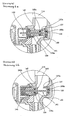
- 5a and 5b are enlarged representations of a cross section of a valve in an automatic pump after another Embodiment of the present invention is used, and clarify the construction and operation of the automatic Pump. The following is just the difference between the present embodiment and the first embodiment described.
- An elastic member 181 such as a spring is between the Valve cover 150 and the second end side 143 of the valve 140 arranged. If no fluid is expelled from the outlet pipe 115 the elastic member 181 forces the valve 140 to be linear Movement so that the inclined valve surface 145 of the valve 140 on the first inclined surface 137a of the contact piece 137 and the second inclined surface 139a of the contact ring 139 of the guide member 130 is applied.
- the elastic member 181 continues to support the valve 140 elastic in such a way that the inclined valve surface 145 of the Valve 140 fixed to the first sloping surface 137a of the contact piece 137 and the second inclined surface 139a of the contact ring 139 of the Guide member 130 abuts.
- 6a and 6b are enlarged representations of a cross section of a valve in an automatic pump after another Embodiment of the present invention is used, and clarify the construction and operation of the automatic Pump. The following is just the difference between the present embodiment and the first embodiment described.
- a second magnet 185a is near the first end side 142 of the Valve 140 is arranged, and a third magnet 185b is in the foot 133 of the Guide member 130 arranged.
- the second magnet 185a and the third magnet 185b arranged so that their opposite polarities are so arranged side by side that an attractive force acts between the magnets. Work through it the second magnet 185a and the third magnet 185b together to to force the valve 140 to move linearly so that the oblique valve surface 145 of valve 140 on the first oblique Surface 137a of the contact piece 137 and on the second slope Surface 139a of the contact ring 139 of the guide member 130 rests, when no fluid is discharged through the outlet pipe 115.
- the second magnet 185a and third magnet 185b continue to assist the valve in such a way that the inclined valve surface 145 of the Valve 140 fixed to the first sloping surface 137a of the contact piece 137 and the inclined surface 139a of the contact ring 139 of the Guide member 130 abuts.
Landscapes
- Engineering & Computer Science (AREA)
- Mechanical Engineering (AREA)
- General Engineering & Computer Science (AREA)
- Structures Of Non-Positive Displacement Pumps (AREA)
- Control Of Non-Positive-Displacement Pumps (AREA)
Abstract
Description
Claims (10)
- Automatische Pumpe, umfassend:ein Gehäuse aus Metall, in dem ein Fluidkanal mit einem ersten Ende und einem zweiten Ende geformt ist, wobei das erste Ende mit einem Einlaßrohr verbunden ist, welches mit einer Wasserquelle verbunden ist, und das zweite Ende mit einem Auslaßrohr verbunden ist, welches mit einer Verbraucherseite verbunden ist, und wobei das Gehäuse ein Steuerwerk an einer Seite des Gehäuses hat;ein im Gehäuse angeordnetes Flügelrad, welches Fluid durch das Einlaßrohr ansaugt und durch das Auslaßrohr ausstößt;einen außerhalb des Gehäuses angeordneten Motor, der das Flügelrad nach Maßgabe des Steuerwerks dreht;ein Führungsglied, das an einem Abschnitt des Fluidkanals des Gehäuses in der Nähe des Auslaßrohrs angeordnet ist;ein Ventil, in welches das Führungsglied so eingesetzt wird, daß das Führungsglied in linearer Richtung durch das Ventil hin- und herbewegt werden kann, wobei das Ventil eine erste Endseite hat, auf die Druck im Einlaßrohr wirkt, und eine zweite Endseite hat, auf die Druck im Auslaßrohr wirkt, und das Ventil durch den Druckunterschied zwischen dem Einlaßrohr und dem Auslaßrohr linear in einer Richtung auf die zweite Endseite des Ventils zu bewegt wird, wodurch das Einlaßrohr 113 und das Auslaßrohr miteinander verbunden werden, wenn Fluid durch das Auslaßrohr ausgestoßen wird, und das Ventil am Führungsglied anliegt und dadurch das Einlaßrohr und das Auslaßrohr voneinander trennt, wenn kein Fluid durch das Auslaßrohr ausgestoßen wird;und ein erstes Mittel zum Ein- und Ausschalten des Steuerwerks, wobei das erste Mittel das Ventil zwingt, eine lineare Bewegung durchzuführen, so daß das Ventil an dem Führungsglied anliegt, wenn kein Fluid durch das Auslaßrohr ausgestoßen wird.
- Automatische Pumpe nach Anspruch 1, dadurch gekennzeichnet, daß das Gehäuse eine Sitzvertiefung mit einer Stufe hat, auf der das Führungsglied sitzt, und in einem Abschnitt des Gehäuses gegenüber der Sitzvertiefung eine Ventilbetätigungsöffnung geformt ist, und das Führungsglied eine Basis, einen Fuß, eine Führungsstange, ein Kontaktstück und einen Kontaktring umfaßt, wobei die Basis scheibenförmig ist und in die Stufe der Sitzvertiefung eingesetzt wird und sich der Fuß von einer ersten Fläche der Basis so erstreckt, daß er an einer Bodenfläche der Sitzvertiefung anliegt, und sich die Führungsstange von einem mittleren Abschnitt der anderen Fläche der Basis durch die Ventilbetätigungsöffnung und durch das Ventil hindurch erstreckt und sich das Kontaktstück von einer oberen Hälfte eines Umfangs einer zweiten Fläche der Basis erstreckt, wobei das Kontaktstück es möglich macht, daß zwischen der Basis und einer ersten Endseite des Ventils ein erster Raum gebildet wird, in den Fluid im Einlaßrohr eingeleitet wird, und sich der Kontaktring vom Kontaktstück erstreckt, wobei das Einlaßrohr und das Auslaßrohr voneinander getrennt sind, wenn das Kontaktstück und der Kontaktring an einer äußeren zylindrischen Fläche des Ventils anliegen, und das Ventil eine solche Länge hat, daß die zweite Endseite des Ventils in der Ventilbetätigungsöffnung angeordnet ist, wenn das Kontaktstück und der Kontaktring an einer äußeren zylindrischen Fläche des Ventils anliegen, und die Ventilbetätigungsöffnung von einem Ventildeckel verdeckt wird, der aus einem nicht magnetisch leitfähigen Material hergestellt wird und der die zweite Endseite des Ventils und ein Ende der durch das Ventil hindurch verlaufenden Führungsstange verdeckt, wobei der Ventildeckel es möglich macht, daß zwischen dem Ventildeckel und der zweiten Endseite des Ventils ein zweiter Raum definiert wird, in den Fluid aus dem Auslaßrohr 115 eingeführt wird.
- Automatische Pumpe nach Anspruch 2, dadurch gekennzeichnet, daß das Kontaktstück eine erste schräge Fläche und der Kontaktring eine zweite schräge Fläche hat und das Ventil eine schräge Ventilfläche um das Ventil herum hat, wobei die erste schräge Fläche und die zweite schräge Fläche die gleiche Neigung haben und wobei das Kontaktstück und der Kontaktring zu einem Teil zusammengefaßt sind und in derselben Ebene angeordnet sind, so daß die erste schräge Fläche des Kontaktstücks und die zweite schräge Fläche des Kontaktrings zusammen eine ellipsoidale Form bilden, wobei die schräge Ventilfläche eine Neigung hat, die identisch ist mit der Neigung der ersten schrägen Fläche und der zweiten schrägen Fläche, so daß die schräge Ventilfläche eng an der ersten schrägen Fläche und der zweiten schrägen Fläche anliegen kann.
- Automatische Pumpe nach Anspruch 2, dadurch gekennzeichnet, daß das Gehäuse abgefaste flache Ecken hat, die mit einer gleichen Neigung gegenüber der ersten schrägen Fläche des Kontaktstücks und der zweiten schrägen Fläche des Kontaktrings angeordnet sind.
- Automatische Pumpe nach Anspruch 2, dadurch gekennzeichnet, daß die Führungsstange einen ellipsoidalen Querschnitt hat.
- Automatische Pumpe nach Anspruch 2, dadurch gekennzeichnet, daß das Steuerwerk einen Blattfederschalter umfaßt, der in der Nähe des Ventildeckels angeordnet ist, und das erste Mittel einen ersten Magneten an der zweiten Endseite des Ventils umfaßt und der erste Magnet den Blattfederschalter ein- und ausschaltet, wobei der erste Magnet vom Gehäuse angezogen wird.
- Automatische Pumpe nach Anspruch 6, weiter umfassend ein zweites Mittel, um das Ventil zu einer linearen Bewegung zu zwingen, so daß das Ventil am Führungsglied anliegt, wenn kein Fluid durch das Auslaßrohr ausgestoßen wird.
- Automatische Pumpe nach Anspruch 7, dadurch gekennzeichnet, daß das zweite Mittel ein elastisches Glied umfaßt, das zwischen dem Ventildeckel und der zweiten Endseite des Ventils angeordnet ist.
- Automatische Pumpe nach Anspruch 7, dadurch gekennzeichnet, daß das zweite Mittel einen zweiten Magneten und einen dritten Magneten umfaßt, wobei der zweite Magnet an der ersten Endseite des Ventils und der dritte Magnet am Führungsglied angeordnet ist, wobei der zweite Magnet und der dritte Magnet so angeordnet sind, daß ihre entgegengesetzten Polaritäten nebeneinander angeordnet sind, so daß eine Anziehungskraft zwischen dem zweiten und dem dritten Magneten wirkt.
- Automatische Pumpe nach Anspruch 2, dadurch gekennzeichnet, daß die erste Endseite des Ventils eine Fläche hat, die kleiner ist als die Fläche der zweiten Endseite des Ventils.
Applications Claiming Priority (2)
| Application Number | Priority Date | Filing Date | Title |
|---|---|---|---|
| KR10-2001-0070973A KR100411513B1 (ko) | 2001-11-15 | 2001-11-15 | 자동펌프 |
| KR2001070973 | 2001-11-15 |
Publications (3)
| Publication Number | Publication Date |
|---|---|
| EP1312803A2 true EP1312803A2 (de) | 2003-05-21 |
| EP1312803A3 EP1312803A3 (de) | 2004-01-21 |
| EP1312803B1 EP1312803B1 (de) | 2007-10-17 |
Family
ID=19715993
Family Applications (1)
| Application Number | Title | Priority Date | Filing Date |
|---|---|---|---|
| EP02016058A Expired - Lifetime EP1312803B1 (de) | 2001-11-15 | 2002-07-19 | Automatische Pumpe |
Country Status (4)
| Country | Link |
|---|---|
| EP (1) | EP1312803B1 (de) |
| KR (1) | KR100411513B1 (de) |
| CN (1) | CN2566017Y (de) |
| DE (1) | DE50211077D1 (de) |
Cited By (2)
| Publication number | Priority date | Publication date | Assignee | Title |
|---|---|---|---|---|
| EP2299084A1 (de) * | 2009-09-16 | 2011-03-23 | Pierburg Pump Technology GmbH | Mechanische Kühlpumpe |
| CN110285078A (zh) * | 2019-07-23 | 2019-09-27 | 浙江耀达智能科技股份有限公司 | 一种水泵控制器 |
Families Citing this family (3)
| Publication number | Priority date | Publication date | Assignee | Title |
|---|---|---|---|---|
| KR100583402B1 (ko) * | 2005-01-14 | 2006-05-26 | 윌로펌프 주식회사 | 자동펌프 |
| KR100764855B1 (ko) * | 2006-05-18 | 2007-10-09 | 윌로펌프 주식회사 | 자동펌프 |
| KR101128258B1 (ko) | 2009-10-13 | 2012-03-23 | 윌로펌프 주식회사 | 자동펌프 |
Family Cites Families (10)
| Publication number | Priority date | Publication date | Assignee | Title |
|---|---|---|---|---|
| CH183756A (de) * | 1935-10-17 | 1936-04-30 | Sulzer Ag | Steuerungseinrichtung mit Servomotor zum selbsttätigen Steuern eines in einer Druckleitung, insbesondere in einer langen Zentrifugalpumpen-Druckleitung angeordneten Abschlussorganes in Abhängigkeit von dem in der Druckleitung herrschenden Druck. |
| GB1184650A (en) * | 1966-03-04 | 1970-03-18 | Lucas Industries Ltd | Liquid Pumps. |
| JPS56154185A (en) * | 1980-04-28 | 1981-11-28 | Hitachi Ltd | Capacity controller for compressor |
| JPS60111088A (ja) * | 1983-11-18 | 1985-06-17 | Sanyo Electric Co Ltd | 自動式ポンプ |
| JPH07145874A (ja) * | 1993-11-25 | 1995-06-06 | Matsushita Electric Works Ltd | 排気装置 |
| IT1268937B1 (it) * | 1994-01-14 | 1997-03-18 | Co Ge S R L | Dispositivo per il comando di un impianto di distribuzione d'acqua |
| DE4438705A1 (de) * | 1994-10-29 | 1996-05-02 | Wolfgang Kube | Selbsttätig arbeitende Absperrarmatur für Kreiselpumpen |
| KR100197690B1 (ko) * | 1995-07-26 | 1999-06-15 | 윤종용 | 냉장고의 물분배기 |
| EP1232343A1 (de) * | 1999-11-10 | 2002-08-21 | Aker Maritime ASA | System, um die betriebsbedingungen einer mechanischen pumpe zu regeln und regelventil dafür |
| KR100372321B1 (ko) * | 2000-04-14 | 2003-02-17 | 박헌우 | 영구자석을 이용한 차압밸브 |
-
2001
- 2001-11-15 KR KR10-2001-0070973A patent/KR100411513B1/ko not_active Expired - Lifetime
-
2002
- 2002-07-19 EP EP02016058A patent/EP1312803B1/de not_active Expired - Lifetime
- 2002-07-19 DE DE50211077T patent/DE50211077D1/de not_active Expired - Lifetime
- 2002-08-13 CN CN02246879U patent/CN2566017Y/zh not_active Expired - Lifetime
Cited By (4)
| Publication number | Priority date | Publication date | Assignee | Title |
|---|---|---|---|---|
| EP2299084A1 (de) * | 2009-09-16 | 2011-03-23 | Pierburg Pump Technology GmbH | Mechanische Kühlpumpe |
| WO2011032808A1 (en) * | 2009-09-16 | 2011-03-24 | Pierburg Pump Technology Gmbh | Mechanical coolant pump |
| US8955471B2 (en) | 2009-09-16 | 2015-02-17 | Pierburg Pump Technology Gmbh | Mechanical coolant pump |
| CN110285078A (zh) * | 2019-07-23 | 2019-09-27 | 浙江耀达智能科技股份有限公司 | 一种水泵控制器 |
Also Published As
| Publication number | Publication date |
|---|---|
| KR100411513B1 (ko) | 2003-12-18 |
| KR20020001682A (ko) | 2002-01-09 |
| CN2566017Y (zh) | 2003-08-13 |
| EP1312803B1 (de) | 2007-10-17 |
| EP1312803A3 (de) | 2004-01-21 |
| DE50211077D1 (de) | 2007-12-06 |
Similar Documents
| Publication | Publication Date | Title |
|---|---|---|
| EP0271765B1 (de) | Eigenmediumgesteuertes, durch ein vorzugsweise elektromagnetisch betätigtes Steuerventil auslösbares Ventil | |
| EP2488776B1 (de) | Druckhalteventil | |
| DE102017125761A1 (de) | Elektromagnetisches Ventil | |
| EP1072556A1 (de) | Zapfsystem für Tanksäulen | |
| DE3346290A1 (de) | Magnetventil | |
| DE1528605B1 (de) | Zerstäuberpumpe mit positiv wirkendem Auslassventil | |
| DE69431543T2 (de) | ventilanordnung | |
| DE4024726A1 (de) | Membranventil | |
| CH654882A5 (de) | Impulsventil. | |
| DE3042328A1 (de) | Kolbenpumpe | |
| DE3152349A1 (en) | Back-flow prevention valve | |
| EP0901591B1 (de) | Magnetventil | |
| DE3500500A1 (de) | Stellventil | |
| EP1312803B1 (de) | Automatische Pumpe | |
| EP2148986B1 (de) | Pumpe | |
| DE202025104530U1 (de) | Ölauslassdüse für Ölfässer | |
| DE2844142C2 (de) | Durchfluß-Steuerventil | |
| DE3855689T2 (de) | Hin- und herbewegende Schaltungsstruktur für Pumpen | |
| DE3134613C2 (de) | ||
| EP0791772A2 (de) | Dreiwegeventil für hydraulische Schnittstelle | |
| DE1802976A1 (de) | Pneumatischer Pulsator | |
| DE1653614B2 (de) | Drehschieberventil für eine Schlammpumpe, z.B. Betonpumpe | |
| EP1249611B1 (de) | Pumpe mit Strömungsventil | |
| DE3743842C2 (de) | Überflutungssicherung für Waschmaschinen | |
| DE29611173U1 (de) | Anordnung von mindestens zwei in Reihe geschalteten Verdrängerpumpen |
Legal Events
| Date | Code | Title | Description |
|---|---|---|---|
| PUAI | Public reference made under article 153(3) epc to a published international application that has entered the european phase |
Free format text: ORIGINAL CODE: 0009012 |
|
| AK | Designated contracting states |
Designated state(s): AT BE BG CH CY CZ DE DK EE ES FI FR GB GR IE IT LI LU MC NL PT SE SK TR |
|
| AX | Request for extension of the european patent |
Extension state: AL LT LV MK RO SI |
|
| PUAL | Search report despatched |
Free format text: ORIGINAL CODE: 0009013 |
|
| AK | Designated contracting states |
Kind code of ref document: A3 Designated state(s): AT BE BG CH CY CZ DE DK EE ES FI FR GB GR IE IT LI LU MC NL PT SE SK TR |
|
| AX | Request for extension of the european patent |
Extension state: AL LT LV MK RO SI |
|
| 17P | Request for examination filed |
Effective date: 20040407 |
|
| AKX | Designation fees paid |
Designated state(s): DE FR GB IT |
|
| GRAJ | Information related to disapproval of communication of intention to grant by the applicant or resumption of examination proceedings by the epo deleted |
Free format text: ORIGINAL CODE: EPIDOSDIGR1 |
|
| GRAP | Despatch of communication of intention to grant a patent |
Free format text: ORIGINAL CODE: EPIDOSNIGR1 |
|
| GRAS | Grant fee paid |
Free format text: ORIGINAL CODE: EPIDOSNIGR3 |
|
| GRAA | (expected) grant |
Free format text: ORIGINAL CODE: 0009210 |
|
| AK | Designated contracting states |
Kind code of ref document: B1 Designated state(s): DE FR GB IT |
|
| REG | Reference to a national code |
Ref country code: GB Ref legal event code: FG4D Free format text: NOT ENGLISH |
|
| REF | Corresponds to: |
Ref document number: 50211077 Country of ref document: DE Date of ref document: 20071206 Kind code of ref document: P |
|
| GBT | Gb: translation of ep patent filed (gb section 77(6)(a)/1977) |
Effective date: 20080116 |
|
| ET | Fr: translation filed | ||
| PLBE | No opposition filed within time limit |
Free format text: ORIGINAL CODE: 0009261 |
|
| STAA | Information on the status of an ep patent application or granted ep patent |
Free format text: STATUS: NO OPPOSITION FILED WITHIN TIME LIMIT |
|
| 26N | No opposition filed |
Effective date: 20080718 |
|
| PGFP | Annual fee paid to national office [announced via postgrant information from national office to epo] |
Ref country code: DE Payment date: 20140716 Year of fee payment: 13 |
|
| PGFP | Annual fee paid to national office [announced via postgrant information from national office to epo] |
Ref country code: FR Payment date: 20140708 Year of fee payment: 13 Ref country code: GB Payment date: 20140716 Year of fee payment: 13 |
|
| PGFP | Annual fee paid to national office [announced via postgrant information from national office to epo] |
Ref country code: IT Payment date: 20140716 Year of fee payment: 13 |
|
| REG | Reference to a national code |
Ref country code: DE Ref legal event code: R119 Ref document number: 50211077 Country of ref document: DE |
|
| GBPC | Gb: european patent ceased through non-payment of renewal fee |
Effective date: 20150719 |
|
| PG25 | Lapsed in a contracting state [announced via postgrant information from national office to epo] |
Ref country code: GB Free format text: LAPSE BECAUSE OF NON-PAYMENT OF DUE FEES Effective date: 20150719 Ref country code: IT Free format text: LAPSE BECAUSE OF NON-PAYMENT OF DUE FEES Effective date: 20150719 Ref country code: DE Free format text: LAPSE BECAUSE OF NON-PAYMENT OF DUE FEES Effective date: 20160202 |
|
| REG | Reference to a national code |
Ref country code: FR Ref legal event code: ST Effective date: 20160331 |
|
| PG25 | Lapsed in a contracting state [announced via postgrant information from national office to epo] |
Ref country code: FR Free format text: LAPSE BECAUSE OF NON-PAYMENT OF DUE FEES Effective date: 20150731 |