EP2148986B1 - Pumpe - Google Patents
Pumpe Download PDFInfo
- Publication number
- EP2148986B1 EP2148986B1 EP08734663A EP08734663A EP2148986B1 EP 2148986 B1 EP2148986 B1 EP 2148986B1 EP 08734663 A EP08734663 A EP 08734663A EP 08734663 A EP08734663 A EP 08734663A EP 2148986 B1 EP2148986 B1 EP 2148986B1
- Authority
- EP
- European Patent Office
- Prior art keywords
- rocker
- valve
- pump
- switching valve
- chamber
- Prior art date
- Legal status (The legal status is an assumption and is not a legal conclusion. Google has not performed a legal analysis and makes no representation as to the accuracy of the status listed.)
- Active
Links
- 239000012530 fluid Substances 0.000 claims abstract description 53
- 238000007789 sealing Methods 0.000 claims description 16
- 230000010349 pulsation Effects 0.000 claims description 14
- 239000013013 elastic material Substances 0.000 claims description 10
- 239000000463 material Substances 0.000 claims description 7
- 230000007246 mechanism Effects 0.000 claims description 5
- 239000012528 membrane Substances 0.000 claims description 5
- 238000010276 construction Methods 0.000 claims description 3
- 239000002184 metal Substances 0.000 claims description 3
- 230000010355 oscillation Effects 0.000 claims description 3
- 229920002725 thermoplastic elastomer Polymers 0.000 claims description 3
- 230000006835 compression Effects 0.000 claims 5
- 238000007906 compression Methods 0.000 claims 5
- 238000005086 pumping Methods 0.000 abstract description 2
- 238000005192 partition Methods 0.000 description 11
- 238000005299 abrasion Methods 0.000 description 2
- 230000015572 biosynthetic process Effects 0.000 description 2
- 230000000694 effects Effects 0.000 description 2
- 238000009434 installation Methods 0.000 description 2
- 238000000926 separation method Methods 0.000 description 2
- 239000000126 substance Substances 0.000 description 2
- 239000002253 acid Substances 0.000 description 1
- 150000007513 acids Chemical class 0.000 description 1
- 238000005253 cladding Methods 0.000 description 1
- 238000011109 contamination Methods 0.000 description 1
- 230000007423 decrease Effects 0.000 description 1
- 230000005489 elastic deformation Effects 0.000 description 1
- 229920001971 elastomer Polymers 0.000 description 1
- 239000000806 elastomer Substances 0.000 description 1
- 238000005265 energy consumption Methods 0.000 description 1
- 239000006260 foam Substances 0.000 description 1
- 238000004519 manufacturing process Methods 0.000 description 1
- 238000000465 moulding Methods 0.000 description 1
- 238000010943 off-gassing Methods 0.000 description 1
- 230000002028 premature Effects 0.000 description 1
- 238000003825 pressing Methods 0.000 description 1
- 239000007787 solid Substances 0.000 description 1
- 238000003860 storage Methods 0.000 description 1
- 239000000725 suspension Substances 0.000 description 1
Images


Classifications
-
- F—MECHANICAL ENGINEERING; LIGHTING; HEATING; WEAPONS; BLASTING
- F04—POSITIVE - DISPLACEMENT MACHINES FOR LIQUIDS; PUMPS FOR LIQUIDS OR ELASTIC FLUIDS
- F04B—POSITIVE-DISPLACEMENT MACHINES FOR LIQUIDS; PUMPS
- F04B7/00—Piston machines or pumps characterised by having positively-driven valving
- F04B7/0003—Piston machines or pumps characterised by having positively-driven valving the distribution member forming both the inlet and discharge distributor for one single pumping chamber
- F04B7/0011—Piston machines or pumps characterised by having positively-driven valving the distribution member forming both the inlet and discharge distributor for one single pumping chamber and having an oscillating movement
-
- F—MECHANICAL ENGINEERING; LIGHTING; HEATING; WEAPONS; BLASTING
- F04—POSITIVE - DISPLACEMENT MACHINES FOR LIQUIDS; PUMPS FOR LIQUIDS OR ELASTIC FLUIDS
- F04B—POSITIVE-DISPLACEMENT MACHINES FOR LIQUIDS; PUMPS
- F04B43/00—Machines, pumps, or pumping installations having flexible working members
- F04B43/02—Machines, pumps, or pumping installations having flexible working members having plate-like flexible members, e.g. diaphragms
-
- F—MECHANICAL ENGINEERING; LIGHTING; HEATING; WEAPONS; BLASTING
- F16—ENGINEERING ELEMENTS AND UNITS; GENERAL MEASURES FOR PRODUCING AND MAINTAINING EFFECTIVE FUNCTIONING OF MACHINES OR INSTALLATIONS; THERMAL INSULATION IN GENERAL
- F16K—VALVES; TAPS; COCKS; ACTUATING-FLOATS; DEVICES FOR VENTING OR AERATING
- F16K11/00—Multiple-way valves, e.g. mixing valves; Pipe fittings incorporating such valves
- F16K11/02—Multiple-way valves, e.g. mixing valves; Pipe fittings incorporating such valves with all movable sealing faces moving as one unit
- F16K11/04—Multiple-way valves, e.g. mixing valves; Pipe fittings incorporating such valves with all movable sealing faces moving as one unit comprising only lift valves
- F16K11/052—Multiple-way valves, e.g. mixing valves; Pipe fittings incorporating such valves with all movable sealing faces moving as one unit comprising only lift valves with pivoted closure members, e.g. butterfly valves
- F16K11/0525—Multiple-way valves, e.g. mixing valves; Pipe fittings incorporating such valves with all movable sealing faces moving as one unit comprising only lift valves with pivoted closure members, e.g. butterfly valves the closure members being pivoted around an essentially central axis
-
- F—MECHANICAL ENGINEERING; LIGHTING; HEATING; WEAPONS; BLASTING
- F16—ENGINEERING ELEMENTS AND UNITS; GENERAL MEASURES FOR PRODUCING AND MAINTAINING EFFECTIVE FUNCTIONING OF MACHINES OR INSTALLATIONS; THERMAL INSULATION IN GENERAL
- F16K—VALVES; TAPS; COCKS; ACTUATING-FLOATS; DEVICES FOR VENTING OR AERATING
- F16K31/00—Actuating devices; Operating means; Releasing devices
- F16K31/02—Actuating devices; Operating means; Releasing devices electric; magnetic
- F16K31/06—Actuating devices; Operating means; Releasing devices electric; magnetic using a magnet, e.g. diaphragm valves, cutting off by means of a liquid
- F16K31/0603—Multiple-way valves
- F16K31/0624—Lift valves
- F16K31/0627—Lift valves with movable valve member positioned between seats
-
- F—MECHANICAL ENGINEERING; LIGHTING; HEATING; WEAPONS; BLASTING
- F16—ENGINEERING ELEMENTS AND UNITS; GENERAL MEASURES FOR PRODUCING AND MAINTAINING EFFECTIVE FUNCTIONING OF MACHINES OR INSTALLATIONS; THERMAL INSULATION IN GENERAL
- F16K—VALVES; TAPS; COCKS; ACTUATING-FLOATS; DEVICES FOR VENTING OR AERATING
- F16K31/00—Actuating devices; Operating means; Releasing devices
- F16K31/02—Actuating devices; Operating means; Releasing devices electric; magnetic
- F16K31/06—Actuating devices; Operating means; Releasing devices electric; magnetic using a magnet, e.g. diaphragm valves, cutting off by means of a liquid
- F16K31/10—Actuating devices; Operating means; Releasing devices electric; magnetic using a magnet, e.g. diaphragm valves, cutting off by means of a liquid with additional mechanism between armature and closure member
- F16K31/105—Actuating devices; Operating means; Releasing devices electric; magnetic using a magnet, e.g. diaphragm valves, cutting off by means of a liquid with additional mechanism between armature and closure member for rotating valves
Definitions
- the invention relates to a pump with a pump head in which an inlet valve and an outlet valve arranged and connected on the one hand with a working space and on the other hand with a suction port and a pressure port and between the inlet and outlet valves and pump suction / pressure ports, a switching valve for Switching the conveying direction is arranged.
- Oscillating pumps with pressure actuated valves are known and have proven themselves for their simple and robust construction.
- each of the suction and pressure side is provided with a differential pressure operated valve, so inlet and outlet valve, which each allow a predetermined flow direction and lock in the opposite direction the flow.
- the conveying direction is predetermined by the installation of the two pressure-operated valves.
- the conveying direction is independent of the direction of rotation of the pump drive.
- a valve can be connected to the suction and pressure connections, which switches these two ports hydraulically crosswise.
- Such a pump is for example from the international patent application WO 97/10902 (closest prior art) known.
- the pump has a rotary slide valve valve with four fluid connections which is located outside the pump housing and which is connected through a rotatable valve rotor in pairs cross over each other are connectable.
- the valve rotor performs a sliding movement with respect to the valve space inner wall during switching, which can cause abrasion and wear.
- the sealing of the valve, in particular the outer operating lever, is difficult and expensive.
- Such known valves generally do not satisfy the prescribed by the associated, preferably designed as a diaphragm pump pump properties in particular with regard to the chemical resistance, a hermetic seal, the type of seal, the dry running safety, ice crush resistance and the like.
- such separate valves are structurally complex because more components are required and thereby build larger valves. Also with regard to the hydraulic connection and sealing between the pump and the valve more effort is required, among other things, because additional seals between the inlet and outlet valves and the changeover valve are required.
- a rocker valve with pneumatic pilot control which comprises a housing with pressure medium connections, in which housing a between two end positions about an axis movable and cooperating with at least one sealing surface for two connected via a throttle pressure medium connections rocker is used, wherein a leg of the rocker over a pilot control port can be acted upon by a pilot pressure and the rocker in one end position connects a pressure medium connection with the supply pressure connection and in the other end position the other pressure medium connection with a vent connection.
- a vacuum milking apparatus in which a pump is provided with a pump head, in which an inlet valve and an outlet valve arranged and connected on the one hand with a working frame and on the other hand with a suction port and a pressure port, wherein a switching valve is provided for switching the conveying direction ,
- a pump in which a valve body oscillates to effect the opening and closing of the pump ports required for the pumping operation.
- a valve device which comprises a switching element designed as a switching rocker to form an amplifier, wherein on the both sides of the pivoting range of the rocker arm rocker arms each acts via a control channel acted upon by a low control pressure actuating diaphragm and each one of a channel mouth, which fluid flows for high pressure and high throughput is provided, associated closure part is formed.
- Object of the present invention is to provide a pump of the type mentioned, which is easily switchable in its conveying direction, but still maintaining the simple and robust structure.
- a particularly simple and compact construction of the changeover valve according to the invention is given by the formation of the changeover valve as a rocker valve with a rocker and both sides of a rocker bearing rocker parts.
- the rocker parts form valve body for closing fluid connections of the changeover valve.
- This embodiment has, inter alia, the advantage that no sliding parts are present in the fluid area, so that accordingly no abrasion and no contamination of the pumped medium can occur. There are also no sliding seals from the fluid area to the outside. Therefore, the switching valve is also suitable for solutions, acids, alkalis,
- the switching valve has two adjacently disposed, separate chambers, each having three fluid ports, of which two are alternately closed by the rocker parts.
- the three fluid connections of the one chamber of the switching valve connected to the valve suction port of the inlet valve and the other two, alternately through the rocker located in this chamber part closable fluid ports with pump suction / pressure ports of the three fluid ports of the another chamber is connected to the valve-pressure port of the outlet valve and the other two, closable to the pump suction / pressure ports and wherein the pump suction / pressure ports alternately a pump-pressure port or a depending on the Umschaltventil position Form pump suction port.
- the respectively closed or opened fluid ports of both chambers are connected to different pump suction / pressure ports.
- one of the two suction / pressure ports in one position of the switching valve forms a pump suction port and the other suction / pressure port forms a pump pressure port, while in the other position of the switching valve the pump suction port to the pump pressure port and the Pump pressure port to the pump suction port is.
- a partition between the two chambers is designed as a rocker bearing.
- the partition wall and the rocker support are at least partially elastic, wherein the rocker has an outwardly guided, sealed continuation as an external point of attack for actuating the valve rocker.
- the rocker can be moved from the outside, for example, mechanically controlled, the movement is made possible by elastic deformation in the rocker bearing, so that a mechanism with sliding seal can be avoided.
- the changeover valve has a rocker core made of comparatively rigid material, for example metal, and an at least partially cladding of the rocker core made of soft elastic material.
- the rocker core made of rigid material ensures sufficient stability of the rocker.
- the rocker core preferably extends continuously at least up to the fluid connections that can be closed alternately by the rocker parts.
- the sheath is only partially available in the area of the closable fluid connections, the material and manufacturing costs can be reduced.
- this embodiment is advantageous.
- the entire rocker core is enveloped by a soft elastic, resistant material.
- the entire rocker core is protected from chemical attack by the fluid.
- An advantageous embodiment provides that the envelope of the rocker core of soft elastic material extends into the region of the partition wall and forms it.
- valve chambers and the partition wall located therebetween a circumferential Having sealing wall, which consists of soft elastic material and is preferably integrally connected to the partition wall and the casing of the rocker core.
- the envelope of the rocker core is made of a vulcanized or thermoplastic elastomer.
- valve seats in conjunction with the feature that the closable by the rocker fluid connections of the switching valve are provided with valve seats, as is provided for a reliable sealing of the valve rocker on the valve seats.
- a chemically resistant and externally hermetically sealed design is thus possible.
- the two halves of the rocker can also be designed as a separate part including the respective seal, which can be controlled in parallel by means of external mechanics.
- the connected to the valve suction port of the pump chamber of the changeover valve may be connected to a vibration chamber.
- This pulsations in the suction line can be reduced in oscillating diaphragm pumps and vacuum peaks are avoided. Phenomena such as outgassing and cavitation are thereby reduced.
- the chamber of the switching valve connected to the valve-pressure port of the pump may be connected to a pulsation damper to smooth out exhaust-side pulsations.
- the vibration chamber and / or the pulsation damper are integrated into the pump head.
- a diaphragm pump 1 From a diaphragm pump 1 is in Fig.1 the region of the pump head 2 is shown in a longitudinal section, wherein a pump diaphragm 3, which can be moved back and forth according to the double arrow PF1, an inlet valve 4, an outlet valve 5 and a changeover valve 6 can be seen.
- the pump diaphragm 3 limits a working space 7, which with an inlet to the inlet valve 4 and an outlet to the outlet valve 5 is connected.
- the dot-dash line within the working space 7 indicates approximately the position of the diaphragm in top dead center position.
- the inlet valve 4, facing away from the working space 7, is connected to a valve suction port 8 and the outlet valve 5 is connected to a valve pressure port 9.
- the suction port 8 and the pressure port 9 lead from the valves 4, 5 to the switching valve 6. With the help of the switching valve 6, the conveying direction can be switched.
- the switching valve 6 is connected to a first suction / pressure port 10 and to a second suction / pressure port 11.
- the first connection 10 forms a suction connection and the connection 11 forms a pressure connection
- the first connection 10 forms a pressure connection and the second connection 11 forms a suction connection.
- the pump head is constructed essentially by three plates with the valves 4, 5, 6 arranged therein or in between, which are placed on the pump housing 12.
- the pump can be easily rebuilt and used with or without a changeover valve.
- the changeover module with the changeover valve 6 can also be used separately in conjunction with other pumps or other applications.
- the switching valve 6 is formed as a rocker valve with a rocker 16 and both sides of a rocker bearing 17 rocker parts 16a, 16b. How good in particular in Fig.1 and 2 recognizable, the switching valve 6 has two juxtaposed, separate chambers 18,19, each having three fluid connections. In each case two of the fluid connections of a chamber, namely the fluid connections 20a, 20b of the chamber 18 and the fluid connections 21a, 21b of the chamber 19 are alternately closed by the rocker parts 16a, 16b.
- the rocker parts 16a, 16b form valve body.
- the third fluid port 36 of the chamber 18 is connected to the valve suction port 8 and the third fluid port 37 of the chamber 19 to the valve 9.
- Each simultaneously closed or simultaneously opened fluid ports 20a, 21b; 20b, 21a of both chambers 18,19 are connected to different suction / pressure ports 11.
- the fluid port 20a of the chamber 18 and the fluid port 21a of the chamber 19 are connected to the suction / pressure port 10 and the fluid port 20b of the chamber 18 and the fluid port 21b of the chamber 19 to the second suction / pressure port 11.
- the terminal 10 forms a pressure port while the port 11 forms a suction port.
- the conveying direction is reversed, so that the terminal 10 the Suction connection and the connection 11 form the pressure connection.
- the respective fluid streams are in Fig.1 through the arrows PF2 and in Fig.2 indicated by the arrows PF3.
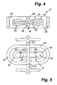
- the switching valve 6 is preferably formed as a one-piece installation unit, as well in the 3 to 5 is recognizable.
- the switching valve 6 has a rocker core 22, for example made of metal and a sheath 23 of the rocker core of soft elastic material.
- This envelope 23 forms in the region of the rocker bearing 17 a partition wall 24 between the two chambers 18,19.
- the rocker 16 and the partition wall 24 are bounded by a circumferential sealing wall 25, which also forms the outer boundary of the two chambers 18 and 19 at the same time.
- These sealing wall 25 is integrally connected in the embodiment with the partition wall 24 and the enclosure 23.
- the material for these parts is elastic, so that on the one hand the necessary seals when clamping between the connection plate 15 and the center plate 14 in the region of the sealing wall 25 and the partition 24 is given and on the other hand, but also the mobility of the rocker 16.
- Als soft elastic material for example, vulcanized elastomers or thermoplastic elastomers in question.
- the sealing wall 25 is annular and is in the functional position ( Fig.1 and 2 ) in annular grooves 26 on the one hand, the connection plate 15 and on the other hand, the center plate 14 sealingly.
- the chambers 18 and 19 are thereby limited in each case by a part of the sealing wall 25, the partition wall 24 and the middle plate 14 and the connection plate 15.
- the rocker core 22 has in the region of its rocker bearing 17, the partition wall 24 and the sealing wall 25 to the outside by cross Continuations 27 (compare Figure 3 and 5 ) which serve as external points of attack for actuating the valve rocker 16.
- an electric magnetic drive can be provided as an actuating drive for the rocker 16
- an actuating lever 28 can be seen, which is connectable to the continuations 27 and on the one hand a solenoid for adjusting the rocker engages in a switching position on the other hand acts in the opposite direction, a return spring which moves the rocker 16 in the other switching position and holds.
- the spring can be dimensioned or adjustable so that an overpressure limitation is formed.
- a manually operable, external hand lever can be provided for actuating the rocker 16.
- the continuations 27, which are guided outward on both sides of the rocker core in the area of the rocker bearing 17, can also serve for the outer mounting of the rocker 16. This storage can be done on outer housing parts.
- the rocker parts 16a, 16b have at their ends with the valve seats 29 of the closable fluid connections cooperating projections 30 as valve body, which are shaped so that in the respective inclined position of the rocker 16 is a good seal of the respective fluid connections.
- the elastic sheath 23 is designed to be somewhat larger with respect to their layer thickness and arranged the contact surface according to the tilting position of the rocker obliquely. Due to the larger layer thickness, a greater flexibility and thus a better sealing ability is given.
- the closable fluid connections 20a, 20b, 21a, 21b have the same cross sections. But there is also the possibility that the connected to the outlet valve 5 chamber 19, closable fluid connections 21a, 21b has a larger passage cross-section than that of the closable fluid ports 20a, 2Qb of the other chamber 18, which is connected to the inlet valve 4.
- the pressure forces acting on the rocker 16 cause a self-energizing closing and smaller driving forces.
- closable fluid connections 21a, 21b with the larger passage cross-section is assigned a molding 30 with a greater layer thickness than the closable fluid connections 20a, 20b of the other chamber 18, readjusting of the rocker 16 can occur in the area of the rocker support 17 when the bearing point swerves.
- the actuating forces which are applied from the outside and transmitted to the rocker 16, are composed of forces for deformation in the region of the elastic rocker bearing 17, pressure forces for closing the valve seats and forces for pressing on the valve seats with a certain deformation of the elastic Enclosure, which is required for a reliable seal.
- a pulsation damper 34 is provided, which is connected to the chamber 19, which is connected to the valve-pressure port.
- the pulsation damper 34 has a pulsation chamber with a separation membrane 35, wherein the separation membrane is supported by a volume-compressible material, for example foam.
- Both the oscillation chamber 31 and the pulsation damper 34 are integrated in the pump head 2 in the exemplary embodiment.
- the vibrating diaphragm 32 may be integrally connected to the adjacent valve plate of the intake valve 4. This also applies analogously to the separating diaphragm 35 of the pulsation damper 34, the position of the separating diaphragm and the valve plate of the outlet valve 5 being aligned relative to one another.
- an integrally continuous membrane and valve plate for the pulsation damper, the vibration chamber and the inlet and outlet valves may be provided.
Landscapes
- Engineering & Computer Science (AREA)
- General Engineering & Computer Science (AREA)
- Mechanical Engineering (AREA)
- Reciprocating Pumps (AREA)
- Details Of Reciprocating Pumps (AREA)
Description
- Die Erfindung bezieht sich auf eine Pumpe mit einem Pumpenkopf, in dem ein Einlassventil und ein Auslassventil angeordnet und einerseits mit einem Arbeitsraum und andererseits mit einem Sauganschluss und einem Druckanschluss verbunden sind und zwischen den Ein- und Auslassventilen und Pumpen-Saug/Druckanschlüssen ein Umschaltventil zum Umschalten der Förderrichtung angeordnet ist.
- Oszillierende Pumpen mit druckbetätigten Ventilen sind bekannt und haben sich wegen ihres einfachen und robusten Aufbaus bewährt. Bei diesen Pumpen ist jeweils die Saugund Druckseite mit einem differenzdruckbetätigten Ventil, also Einlass- und Auslassventil versehen, welche je eine vorgegebene Durchflussrichtung erlauben und in die Gegenrichtung den Durchfluss sperren. Somit ist die Förderrichtung durch den Einbau der beiden druckbetätigten Ventile vorgegeben. Hingegen ist die Förderrichtung unabhängig von der Drehrichtung des Pumpenantriebs.
- Für bestimmte Anwendungen ist es erwünscht, die Förderrichtung umschalten zu können, damit die Pumpe beispielsweise ein austrittsseitiges Gefäß und die Leitungen wieder entleeren kann.
- Zu diesem Zweck kann an die Saug- und Druckanschlüsse ein Ventil angeschlossen werden, welches diese beiden Anschlüsse hydraulisch über Kreuz umschaltet.
- Eine solche Pumpe ist beispielsweise aus der internationalen Patentanmeldung
WO 97/10902 - Solche bekannten Ventile genügen in der Regel auch nicht den durch die damit verbundene, vorzugsweise als Membranpumpe ausgebildete Pumpe vorgegebenen Eigenschaften insbesondere bezüglich der chemischen Beständigkeit, einer hermetischen Abdichtung, der Art der Dichtung, der Trockenlaufsicherheit, der Eisdruckfestigkeit und dergleichen. Außerdem sind solche separaten Ventile konstruktiv aufwändig, da mehr Bauelemente erforderlich sind und dadurch diese Ventile größer bauen. Auch hinsichtlich der hydraulischen Verbindung und Abdichtung zwischen der Pumpe und dem Ventil ist mehr Aufwand erforderlich, unter anderem auch, weil zusätzliche Abdichtungen zwischen den Ein- und Auslassventilen sowie dem Umschaltventil erforderlich sind.
- Aus der
EP 0 933 569 A2 ist ein Wippenventil mit pneumatischer Vorsteuerung bekannt, das ein Gehäuse mit Druckmittelanschlüssen umfasst, in welchem Gehäuse eine zwischen zwei Endstellungen um eine Achse bewegliche und mit zumindest einer Dichtfläche für zwei über eine Drossel miteinander verbundene Druckmittelanschlüsse zusammenwirkenden Wippe eingesetzt ist, wobei ein Schenkel der Wippe über einen Vorsteueranschluss mit einem Vorsteuerdruck beaufschlagbar ist und die Wippe in einer Endstellung einen Druckmittelanschluss mit dem Versorgungsdruckanschluss und in der anderen Endstellung den anderen Druckmittelanschluss mit einem Entlüftungsanschluss verbindet. - Aus der
US 2 526 212 A ist eine Vakuum-Melkvorrichtung bekannt, bei welcher eine Pumpe mit einem Pumpenkopf vorgesehen ist, in welchem ein Einlassventil und ein Auslassventil angeordnet und einerseits mit einem Arbeitsrahmen und andererseits mit einem Sauganschluss und einem Druckanschluss verbunden sind, wobei ein Umschaltventil zum Umschalten der Förderrichtung vorgesehen ist. - Aus der
US 4 213 298 A ist eine hydraulische Steuerung für den Schaft einer Doppelmembranpumpe bekannt. - Aus der
US 3 694 112 ist eine Pumpe bekannt, bei der ein Ventilkörper oszilliert, um das für den Pumpvorgang erforderliche Öffnen und Schließen der Pumpenanschlüsse zu bewirken. - Aus der
DE 198 54 620 A1 ist eine Ventileinrichtung bekannt, die zur Bildung eines Verstärkers ein als Schaltwippe ausgeführtes Schaltelement enthält, wobei an den beidseits des Schwenkbereichs der Schaltwippe liegenden Wippenarmen jeweils eine über einen Steuerkanal durch einen niedrigen Steuerdruck beaufschlagte Betätigungsmembran angreift und jeweils eine einer Kanalmündung, welche für Fluidströme hohen Druckes und hohen Durchsatzes vorgesehen ist, zugeordnete Verschlusspartie ausgebildet ist. - Aufgabe der vorliegenden Erfindung ist es, eine Pumpe der eingangs erwähnten Art zu schaffen, die problemlos in ihrer Förderrichtung umschaltbar ist, wobei aber trotzdem der einfache und robuste Aufbau erhalten bleibt.
- Diese Aufgabe wird bei einer Pumpe der eingangs genannten Art durch die Merkmale des Anspruchs 1 gelöst. Das Umschaltventil ist also insbesondere Teil des Pumpenkopfs und in diesen integriert.
- Dadurch ist kein umständliches, externes Anschließen des Umschaltventils an die Saug- und Druckanschlüsse erforderlich und außerdem ergeben sich dadurch kurze, strömungsgünstige Anschlussverbindungen.
- Ein besonders einfacher und kompakter Aufbau des erfindungsgemäßen Umschaltventils ist durch die Ausbildung des Umschaltventils als Wippenventil mit einer Wippe und beidseits einer Wippenlagerung befindlichen Wippenteilen gegeben. Dabei bilden die Wippenteile Ventilkörper zum Verschließen von Fluidanschlüssen des Umschaltventils.
- Diese Ausführungsform hat unter anderem den Vorteil, dass keine gleitenden Teile im Fluidbereich vorhanden sind, so dass dementsprechend kein Abrieb und keine Verunreinigung des Fördermediums auftreten können. Es sind auch keine Gleitdichtungen vom Fluidbereich nach außen vorhanden. Daher ist das Umschaltventil auch geeignet für Lösungen, Säuren, Laugen,
- Suspensionen und dergleichen Fördermedien. Bei Einsatz von Gleitdichtungen würde der Fluidfilm unter der Dichtung austrocknen und die verbleibenden Feststoffe würden die Dichtung beschädigen und zu deren frühzeitigem Ausfall führen.
- Nach einer bevorzugten Ausführungsform weist das Umschaltventil zwei nebeneinander angeordnete, voneinander getrennte Kammern auf, die jeweils drei Fluidanschlüsse haben, von denen jeweils zwei wechselweise durch die Wippenteile verschließbar sind. Dabei sind von den drei Fluidanschlüssen der einen Kammer des Umschaltventils einer mit dem Ventil-Sauganschluss des Einlassventils und die beiden anderen, wechselweise durch das in dieser Kammer befindliche Wippenteil verschließbaren Fluidanschlüsse mit Pumpen- Saug/Druck-Anschlüssen verbunden, wobei von den drei Fluidanschlüssen der anderen Kammer einer mit dem Ventil-Druckanschluss des Auslassventils und die beiden anderen, verschließbaren mit den Pumpen- Saug/Druck-Anschlüssen verbunden sind und wobei die Pumpen- Saug/Druck-Anschlüsse in Abhängigkeit der Umschaltventil-Stellung wechselweise einen Pumpen-Druckanschluss oder einen Pumpen-Sauganschluss bilden.
- Die jeweils gleichzeitig verschlossenen oder geöffneten Fluidanschlüsse beider Kammern sind dabei an unterschiedliche Pumpen- Saug/Druck-Anschlüsse angeschlossen.
- Somit bildet einer der beiden Saug/Druck-Anschlüsse in der einen Stellung des Umschaltventils einen Pumpen-Sauganschluss und der andere Saug/Druck-Anschluss einen Pumpen-Druckanschluss, während in der anderen Stellung des Umschaltventils der Pumpen-Sauganschluss zum Pumpen-Druckanschluss und der Pumpen-Druckanschluss zum Pumpen-Sauganschluss wird.
- Vorzugsweise ist eine Trennwand zwischen den beiden Kammern als Wippenlagerung ausgebildet.
- Dabei sind insbesondere die Trennwand und die Wippenlagerung zumindest bereichsweise elastisch ausgebildet, wobei die Wippe eine nach außen geführte, abgedichtete Fortsetzung als äußere Angriffsstelle zum Betätigen der Ventilwippe aufweist.
- Damit lässt sich die Wippe von außen bewegen, beispielsweise mechanisch ansteuern, wobei die Bewegung durch elastische Verformung im Bereich der Wippenlagerung ermöglicht ist, so dass ein Mechanismus mit Gleitdichtung vermieden werden kann.
- Nach einer Weiterbildung der Erfindung weist das Umschaltventil einen Wippenkern aus vergleichsweise steifem Material, beispielsweise Metall sowie eine zumindest bereichsweise Umhüllung des Wippenkerns aus weichelastischem Material auf. Der aus steifem Material bestehende Wippenkern sorgt für eine ausreichende Stabilität der Wippe. Bevorzugt erstreckt sich dabei der Wippenkern durchgehend zumindest bis über die wechselweise durch die Wippenteile verschließbaren Fluidanschlüsse.
- Ist die Umhüllung nur teilweise im Bereich der verschließbaren Fluidanschlüsse vorhanden, lassen sich die Werkstoff- und Herstellkosten reduzieren.
- Bei nicht aggressiven Fördermedien oder aber, wenn der Wippenkern ausreichend beständig gegen das geförderte Fluid ist, ist diese Ausführungsform vorteilhaft.
- Bevorzugt ist jedoch vorgesehen, dass der ganze Wippenkern von einem weichelastischen, beständigem Material umhüllt ist. Dadurch ist der ganze Wippenkern vor chemischem Angriff durch das Fluid geschützt.
- Eine vorteilhafte Ausführungsform sieht vor, dass sich die Umhüllung des Wippenkerns aus weichelastischem Material in den Bereich der Trennwand erstreckt und diese bildet.
- Dabei ist es besonders vorteilhaft, wenn die Ventil-Kammern und die dazwischen befindliche Trennwand eine umlaufende Abdichtwand aufweist, welche aus weichelastischem Material besteht und vorzugsweise einstückig mit der Trennwand und der Umhüllung des Wippenkerns verbunden ist.
- Damit werden zusätzliche Verbindungsstellen vermieden und die Teilezahl wird reduziert.
- Vorzugsweise besteht die Umhüllung des Wippenkerns aus einem vulkanisierten oder thermoplastischen Elastomer.
- Insbesondere in Verbindung mit dem Merkmal, dass die von der Wippe verschließbaren Fluidanschlüsse des Umschaltventils mit Ventilsitzen versehen sind, wird so für eine zuverlässige Abdichtung der Ventilwippe auf den Ventilsitzen gesorgt. Insbesondere ist damit auch eine chemiebeständige und nach außen hermetisch dichte Ausführung möglich.
- Erwähnt sei noch, dass die beiden Hälften der Wippe auch je als ein separates Teil einschließlich der jeweiligen Abdichtung ausgeführt sein können, die mittels außen liegender Mechanik parallel angesteuert sein können.
- Nach einer Ausgestaltung der Erfindung kann die mit dem Ventil-Sauganschluss der Pumpe verbundene Kammer des Umschaltventils mit einer Schwingkammer verbunden sein.
- Damit können Pulsationen in der Saugleitung bei oszillierenden Membranpumpen reduziert und Unterdruckspitzen vermieden werden. Phänomene wie Ausgasung und Kavitation werden dadurch verringert.
- Weiterhin kann die mit dem Ventil-Druckanschluss der Pumpe verbundene Kammer des Umschaltventils mit einem Pulsationsdämpfer verbunden sein, um auslassseitige Pulsationen zu glätten.
- Zweckmäßigerweise sind dabei die Schwingkammer und/oder der Pulsationsdämpfer in den Pumpenkopf integriert.
- Zusätzliche Ausgestaltungen der Erfindung sind in den weiteren Unteransprüchen aufgeführt.
- Nachstehend ist die Erfindung mit ihren wesentlichen Einzelheiten anhand der Zeichnungen noch näher erläutert.
-
- Fig. 1
- eine Längsschnittdarstellung einer teilweise dargestellten Membranpumpe mit einem Pumpenkopf und darin befindlichen Ein- und Auslassventilen sowie einem Umschaltventil,
- Fig. 2
- eine etwa
Fig.1 entsprechende Darstellung, hier jedoch mit dem Umschaltventil in der anderen Schaltposition sowie zusätzlich vorgesehener Schwingkammer und Pulsationsdämpfer, - Fig. 3
- eine perspektivische Darstellung eines Umschaltventils,
- Fig. 4
- eine Querschnittdarstellung des Umschaltventils und
- Fig. 5
- eine Aufsicht des Umschaltventils.
- Von einer Membranpumpe 1 ist in
Fig.1 der Bereich des Pumpenkopfes 2 in Längsschnittdarstellung gezeigt, wobei eine gemäß dem Doppelpfeil PF1 hin und her bewegbare Pumpen-Membrane 3, ein Einlassventil 4, ein Auslassventil 5 sowie ein Umschaltventil 6 erkennbar sind. - Die Pumpen-Membrane 3 begrenzt einen Arbeitsraum 7, der mit einem Einlass an das Einlassventil 4 und einem Auslass an das Auslassventil 5 angeschlossen ist. Die strichpunktierte Linie innerhalb des Arbeitsraumes 7 kennzeichnet etwa die Lage der Membrane in oberer Totpunktstellung.
- Das Einlassventil 4 ist, dem Arbeitsraum 7 abgewandt, an einen Ventil-Sauganschluss 8 und das Auslassventil 5 an einem Ventil-Druckanschluss 9 angeschlossen. Der Sauganschluss 8 und der Druckanschluss 9 führen von den Ventilen 4, 5 zu dem Umschaltventil 6. Mit Hilfe des Umschaltventils 6 kann die Förderrichtung umgeschaltet werden.
- Das Umschaltventil 6 ist an einem ersten Saug/Druck-Anschluss 10 sowie an einem zweiten Saug/Druck-Anschluss 11 angeschlossen. Je nach Stellung des Umschaltventils 6 bildet dabei der erste Anschluss 10 einen Sauganschluss und der Anschluss 11 einen Druckanschluss, während in der anderen Stellung des Umschaltventils der erste Anschluss 10 einen Druckanschluss bildet und der zweite Anschluss 11 einen Sauganschluss.
- Im gezeigten Ausführungsbeispiel ist der Pumpenkopf im wesentlichen durch drei Platten mit den darin beziehungsweise dazwischen angeordneten Ventilen 4,5,6 aufgebaut, die auf das Pumpengehäuse 12 aufgesetzt sind. Als erstes befindet sich auf dem Pumpengehäuse 12 eine Zwischenplatte 13, an die sich eine Mittelplatte 14 anschließt. Zwischen diesen beiden Platten 13, 14 befinden sich die Ein- und Auslassventile 4,5. Auf die Mittelplatte 14 ist eine Anschlussplatte 15 aufgesetzt, zwischen der und der Mittelplatte 14 das Umschaltventil 6 eingesetzt ist.
- Das Umschaltventil 6 zusammen mit der Mittelplatte 14 und der Anschlussplatte 15 bilden ein Wechselmodul, welches von dem übrigen Pumpenkopf abnehmbar und durch eine Abschlussplatte mit darin befindlichem Ventil-Saug-Anschluss 8 und Ventil-DruckAnschluss 9 ersetzt werden kann. Die Pumpe lässt sich so wahlweise mit oder ohne Umschaltventil auf einfache Weise umbauen und einsetzen.
- Das Wechselmodul mit dem Umschaltventil 6 kann auch in Verbindung mit anderen Pumpen oder anderen Anwendungen separat eingesetzt werden.
- Das Umschaltventil 6 ist als Wippenventil mit einer Wippe 16 und beidseits einer Wippenlagerung 17 befindlichen Wippenteilen 16a, 16b ausgebildet. Wie gut insbesondere in
Fig.1 und2 erkennbar, weist das Umschaltventil 6 zwei nebeneinander angeordnete, voneinander getrennte Kammern 18,19 auf, die jeweils drei Fluidanschlüsse haben. Jeweils zwei der Fluidanschlüsse einer Kammer, nämlich die Fluidanschlüsse 20a, 20b der Kammer 18 sowie die Fluidanschlüsse 21a, 21b der Kammer 19 sind wechselweise durch die Wippenteile 16a,16b verschließbar. Die Wippenteile 16a,16b bilden dabei Ventilkörper. - Der dritte Fluidanschluss 36 der Kammer 18 ist an den Ventil-Saug-Anschluss 8 und der dritte Fluidanschluss 37 der Kammer 19 an das Ventil 9 angeschlossen. Jeweils gleichzeitig verschlossene oder gleichzeitig geöffnete Fluidanschlüsse 20a,21b; 20b,21a beider Kammern 18,19 sind an unterschiedliche Saug/Druck-Anschlüsse 11 angeschlossen.
- Wie in
Fig.1 und2 erkennbar, ist der Fluidanschluss 20a der Kammer 18 und der Fluidanschluss 21a der Kammer 19 an den Saug/Druckanschluss 10 und der Fluidanschluss 20b der Kammer 18 und der Fluidanschluss 21b der Kammer 19 an den zweiten Saug/Druck-Anschluss 11 angeschlossen. In der Stellung des Umschaltventils 6 gemäßFig.1 bildet der Anschluss 10 einen Druckanschluss während der Anschluss 11 einen Sauganschluss bildet. In der Stellung des Umschaltventils 6 gemäßFig.2 ist die Förderrichtung umgedreht, so dass der Anschluss 10 den Saug-Anschluss und der Anschluss 11 den Druckanschluss bilden. Die jeweiligen Fluidströme sind inFig.1 durch die Pfeile PF2 und inFig.2 durch die Pfeile PF3 gekennzeichnet. - Das Umschaltventil 6 ist vorzugsweise als einstückige Einbaueinheit ausgebildet, wie dies gut in den
Fig.3 bis 5 erkennbar ist. Das Umschaltventil 6 weist einen Wippenkern 22 beispielsweise aus Metall sowie eine Umhüllung 23 des Wippenkerns aus weichelastischem Material auf. Diese Umhüllung 23 bildet im Bereich der Wippenlagerung 17 eine Trennwand 24 zwischen den beiden Kammern 18,19. Die Wippe 16 und auch die Trennwand 24 sind von einer umlaufenden Abdichtwand 25 umgrenzt, die gleichzeitig auch die äußere Abgrenzung der beiden Kammern 18 und 19 bildet. Auch diese Abdichtwand 25 ist im Ausführungsbeispiel einstückig mit der Trennwand 24 sowie der Umhüllung 23 verbunden. - Wie bereits vorerwähnt, ist das Material für diese Teile elastisch, so dass einerseits die notwendigen Abdichtungen beim Einspannen zwischen der Anschlussplatte 15 und der Mittelplatte 14 im Bereich der Abdichtwand 25 und der Trennwand 24 gegeben ist und andererseits aber auch die Beweglichkeit der Wippe 16. Als weichelastisches Material kommen beispielsweise vulkanisierte Elastomere oder thermoplastische Elastomere in Frage.
- Die Abdichtwand 25 ist ringförmig ausgebildet und liegt in Funktionsstellung (
Fig.1 und2 ) in Ringnuten 26 einerseits der Anschlussplatte 15 und andererseits der Mittelplatte 14 dichtend an. Die Kammern 18 und 19 sind dadurch jeweils durch einen Teil der Abdichtwand 25, die Trennwand 24 sowie die Mittelplatte 14 und die Anschlussplatte 15 begrenzt. - Der Wippenkern 22 weist im Bereich seiner Wippenlagerung 17 die Trennwand 24 und die Abdichtwand 25 nach außen durchgreifende Fortsetzungen 27 auf (vergleiche
Fig.3 und5 ) die als äußere Angriffsstellen zum Betätigen der Ventil-Wippe 16 dienen. Als Betätigungsantrieb für die Wippe 16 kann beispielsweise ein Elektro-Magnetantrieb vorgesehen sein. InFig.3 ist ein Betätigungshebel 28 erkennbar, der mit den Fortsetzungen 27 verbindbar ist und an dem einerseits ein Hubmagnet zum Verstellen der Wippe in eine Schaltstellung angreift andererseits in die Gegenrichtung eine Rückstellfeder wirkt, welche die Wippe 16 in die andere Schaltstellung bewegt und hält. Die Feder kann derart dimensioniert oder einstellbar sein, dass eine Überdruckbegrenzung gebildet ist. Im einfachsten Fall kann zur Betätigung der Wippe 16 auch ein manuell betätigbarer, äußerer Handhebel vorgesehen sein. - Die beidseitig des Wippenkerns im Bereich der Wippenlagerung 17 nach außen geführten Fortsetzungen 27 können auch zur äußeren Lagerung der Wippe 16 dienen. Diese Lagerung kann auf äußeren Gehäuseteilen erfolgen.
- Die Wippenteile 16a,16b weisen an ihren Enden mit den Ventilsitzen 29 der verschließbaren Fluidanschlüsse zusammenwirkende Anformungen 30 als Ventilkörper auf, die so geformt sind, dass in der jeweiligen Schräglage der Wippe 16 eine gute Abdichtung der jeweiligen Fluidanschlüsse gegeben ist. Die elastische Umhüllung 23 ist dazu bezüglich ihrer Schichtdicke etwas größer ausgebildet und die Anlagefläche entsprechend der Kipplage der Wippe schräg verlaufend angeordnet. Durch die größere Schichtdicke ist auch eine größere Nachgiebigkeit und damit eine bessere Dichtmöglichkeit gegeben.
- In den gezeigten Ausführungsbeispielen weisen die verschließbaren Fluidanschlüsse 20a,20b,21a,21b gleich große Querschnitte auf. Es besteht aber auch die Möglichkeit, dass die mit dem Auslassventil 5 verbundene Kammer 19, verschließbare Fluidanschlüsse 21a,21b mit einem größeren Durchlassquerschnitt aufweist als die der verschließbaren Fluidanschlüsse 20a,2Qb der anderen Kammer 18, die mit dem Einlassventil 4 verbunden ist. Die dadurch auf die Wippe 16 einwirkenden Druckkräfte bewirken ein selbstverstärkendes Schließen und kleinere Ansteuerkräfte.
- Wenn den verschließbaren Fluidanschlüssen 21a,21b mit dem größeren Durchlassquerschnitt eine Anformung 30 mit größerer Schichtdicke zugeordnet ist, als dem verschließbaren Fluidanschlüssen 20a,20b der anderen Kammer 18, kann ein Nachstellen der Wippe 16 bei einem Ausweichen des Lagerpunktes im Bereich der Wippenlagerung 17 erfolgen.
- Die Stellkräfte, die von außen aufgebracht und auf die Wippe 16 übertragen werden, setzen sich zusammen aus Kräften für die Deformation im Bereich der elastischen Wippenlagerung 17, aus Druckkräften für das Verschließen der Ventilsitze sowie Kräften zum Anpressen auf die Ventilsitze mit einer gewissen Deformation der elastischen Umhüllung, was für eine zuverlässige Abdichtung erforderlich ist.
- Da die Hauptkraftkomponenten nur im Bereich der Endlagen der Wippe 16 auftreten, sind für die Verstellansteuerung besondere Betätigungsmechaniken vorteilhaft, beispielsweise ein Exzenteroder Kniehebel-Mechanismus. Dadurch wird die Wippe in den jeweiligen Endpositionen mit geringem Kraftaufwand auch gegen große Druckkräfte gehalten beziehungsweise verriegelt. Der Selbsthemmungseffekt wird dadurch ausgenützt und ein Elektromagnet als Antrieb müsste nur im Moment der Betätigung bestromt werden und kann ansonsten ruhen, womit der durchschnittliche Energieaufwand sinkt.
- Zur Reduktion einer Pulsation in der Saugleitung kann, wie in
Fig.2 erkennbar, die mit dem Ventil-Saug-Anschluss 8 verbundene Kammer 18 des Umschaltventils 6 mit einer Schwingkammer 31 verbunden sein. Diese Schwingkammer weist ein durch eine Schwingmembrane 32 abgetrenntes Luftpolster 33 auf. Da die Schwingkammer 31 seitlich neben den Einlassventil 4 angeordnet ist, könnte eine einstückige Ausbildung der Schwingmembrane mit der Ventilplatte des Einlassventils vorgesehen sein. Bei einer anderen Anordnung im Bereich des Auslassventiles wäre dann eine Einstückigkeit mit der Ventilplatte des Auslassventils möglich. Weiterhin ist in dem Ausführungsbeispiel nachFig.2 ein Pulsationsdämpfer 34 vorgesehen, der mit der Kammer 19 verbunden ist, welche an dem Ventil-Druckanschluss angeschlossen ist. Der Pulsationsdämpfer 34 weist eine Pulsationskammer mit einer Trennmembrane 35 auf, wobei die Trennmembrane durch ein volumen-kompressibles Material, zum Beispiel Schaumstoff abgestützt ist. - Sowohl die Schwingkammer 31 als auch der Pulsationsdämpfer 34 sind im Ausführungsbeispiel in dem Pumpenkopf 2 integriert.
- Die Schwingmembrane 32 kann mit der benachbarten Ventilplatte des Einlassventils 4 einstückig verbunden sein. Analog gilt dies auch für die Trennmembrane 35 des Pulsationsdämpfers 34, wobei die Lage der Trennmembrane und der Ventilplatte des Auslassventils 5 relativ zueinander entsprechend ausgerichtet sind. Gegebenenfalls kann auch eine einstückig durchgehende Membran- und Ventilplatte für den Pulsationsdämpfer, die Schwingkammer und die Ein- und Auslassventile vorgesehen sein.
Claims (15)
- Pumpe mit einem Pumpenkopf, in dem ein Einlassventil und ein Auslassventil angeordnet und einerseits mit einem Arbeitsraum (7) und andererseits mit einem Sauganschluss und einem Druckanschluss verbunden sind und zwischen den Ein- und Auslassventilen (4,5) und Pumpen- Saug/Druckanschlüssen (10,11) ein Umschaltventil (6) zum Umschalten der Förderrichtung angeordnet ist dadurch gekennzeichnet, dass das Umschaltventil (6) als Wippenventil mit einer Wippe (16) und beidseits einer Wippenlagerung (17) befindlichen Wippenteilen (16a,16b) ausgebildet ist, wobei das Umschaltventil (6) zwei nebeneinander angeordnete, voneinander getrennte Kammern (18,19) aufweist, die jeweils drei Fluidanschlüsse (20a,20b,36; 21a,21b,37) haben, von denen jeweils zwei (20a,20b; 21a,21b) wechselweise durch die Wippenteile (16a,16b) verschließbar sind.
- Pumpe nach Anspruch 1, dadurch gekennzeichnet, dass das Umschaltventil (6) Teil des Pumpenkopfs (2) ist, vorzugsweise in diesen integriert ist und/oder dass die Wippenteile (16a,16b) Ventilkörper zum Verschließen von Fluidanschlüssen des Umschaltventils (6) bilden.
- Pumpe nach Anspruch 1 oder 2, dadurch gekennzeichnet, dass von den drei Fluidanschlüssen (20a,20b,36) der einen Kammer (18) des Umschaltventils (6) ein Fluidanschluss (36) mit dem Ventil-Sauganschluss (8) des Einlassventils (4) und die beiden anderen, wechselweise durch das in dieser Kammer befindliche Wippenteil verschließbaren Fluidanschlüsse (20a,20b) mit Pumpen-Saug/Druck-Anschlüssen (10,11) verbunden sind, dass von den drei Fluidanschlüssen (21a,21b,37) der anderen Kammer ein Fluidanschluss (37) mit dem Ventil-Druckanschluss (9) des Auslassventils (5) und die beiden anderen (21a, 21b) mit den Pumpen- Saug/Druck-Anschlüssen (10,11) verbunden sind und dass die Pumpen- Saug/DruckAnschlüsse (10,11) in Abhängigkeit der Umschaltventil-Stellung wechselweise einen Pumpen-Druckanschluss oder einen Pumpen-Sauganschluss bilden und/oder dass jeweils gleichzeitig verschlossene oder gleichzeitig geöffnete Fluidanschlüsse (20a,21b; 20b,21a) beider Kammern (18,19) an unterschiedliche Pumpen- Saug/Druck-Anschlüsse (10,11) angeschlossen sind.
- Pumpe nach einem der Ansprüche 1 bis 3, dadurch gekennzeichnet, dass die Wippenlagerung (17) als Trennwand (24) zwischen den beiden Kammern (18,19) ausgebildet ist, insbesondere wobei die Trennwand (24) und Wippenlagerung (17) zumindest bereichsweise elastisch ausgebildet sind und wobei die Wippe (16) eine nach außen geführte, abgedichtete Fortsetzung (27) als äußere Angriffsstelle zum Betätigen der Ventilwippe aufweist.
- Pumpe nach einem der Ansprüche 1 bis 4, dadurch gekennzeichnet, dass das Umschaltventil (6) einen Wippenkern (22) aus vergleichsweise steifem Material, beispielsweise Metall sowie eine zumindest bereichsweise Umhüllung (23) des Wippenkerns (22) aus weichelastischem Material aufweist und/oder dass sich der Wippenkern (22) durchgehend zumindest bis über die wechselweise durch die Wippenteile (16a,16b) verschließbaren Fluidanschlüsse (20a,20b,21a,21b) erstreckt.
- Pumpe nach einem der Ansprüche 1 bis 5, dadurch gekennzeichnet, dass sich das weichelastische Material, insbesondere die Umhüllung (23) des Wippenkerns (22) aus weichelastischem Material in den Bereich der Trennwand (24) erstreckt und diese bildet und/oder dass das weichelastische Material, insbesondere die Umhüllung (23) des Wippenkerns (22) aus einem vulkanisierten oder thermoplastischen Elastomer besteht und/oder dass die von der Wippe (16) verschließbaren Fluidanschlüsse (20a,20b, 21a,21b) des Umschaltventils (6) mit Ventilsitzen (29) versehen sind.
- Pumpe nach einem der Ansprüche 1 bis 6, dadurch gekennzeichnet, dass die Ventil-Kammern (18, 19) und die dazwischen befindliche Trennwand (24) von einer umlaufenden Abdichtwand (25) umgrenzt sind, insbesondere wobei die Abdichtwand (25) aus weichelastischem Material besteht und vorzugsweise einstückig mit der Trennwand (24) und der Umhüllung des Wippenkerns (22) verbunden ist.
- Pumpe nach einem der Ansprüche 1 bis 7, dadurch gekennzeichnet, dass der Wippenkern (22) im Bereich seiner Wippenlagerung (17) wenigstens eine, die Trennwand (24) und die Abdichtwand (25) nach außen durchgreifende Fortsetzung (27) aufweist als äußere Angriffsstelle zum Betätigen der Ventilwippe und/oder dass als Betätigungsmechanik zum Verstellen der Wippe (16) ein Excenter- oder Kniehebel-Mechanismus vorgesehen ist.
- Pumpe nach einem der Ansprüche 1 bis 8, dadurch gekennzeichnet, dass als Betätigungsantrieb für die Wippe (16) ein Elektro-Magnetantrieb vorgesehen ist.
- Pumpe nach einem der Ansprüche 1 bis 9, dadurch gekennzeichnet, dass die Wippe (16) durch Federkraft in einer Endlage gehalten ist und durch einen Betätigungsantrieb in die andere Endlage verstellbar ist, insbesondere wobei die Feder zum Halten der Wippe (16) in einer Endlage derart bemessen oder einstellbar ist, dass eine Überdruckbegrenzung gebildet ist.
- Pumpe nach einem der Ansprüche 1 bis 10, dadurch gekennzeichnet, dass zur Betätigung der Wippe (16) ein manuell betätigbarer Handhebel vorgesehen ist und/oder dass beidseitig des Wippenkerns im Bereich seiner Wippenlagerung (17) nach außen geführte, die Trennwand und die Abdichtwand nach außen durchgreifende Fortsetzungen (27) des Wippenkerns (22) vorgesehen sind, die zur äußeren Lagerung der Wippe (16) dienen und/oder dass die wechselweise durch die Wippenteile (16a,16b) verschließbaren Fluidanschlüsse (20a,20b,21a,21b) gleich große Querschnitte aufweisen.
- Pumpe nach einem der Ansprüche 1 bis 11, dadurch gekennzeichnet, dass die mit dem Auslassventil verbundene Kammer (19) des Umschaltventils (6), verschließbare Fluidanschlüsse (21a,21b) mit einem größeren Durchlassquerschnitt aufweist als die der verschließbaren Fluidanschlüsse (20a,20b) der anderen Kammer (18), insbesondere wobei den verschließbaren Fluidanschlüssen (21a,21b) mit dem größeren Durchlassquerschnitt eine Umhüllung (23) des Wippenkerns (22) mit größerer Schichtdicke zugeordnet ist als den verschließbaren Fluidanschlüsse (20a,20b) der anderen Kammer.
- Pumpe nach einem der Ansprüche 1 bis 12, dadurch gekennzeichnet, dass die mit dem Ventil-Sauganschluss (8) der Pumpe verbundene Kammer (18) des Umschaltventils (6) mit einer Schwingkammer (31) verbunden ist und/oder dass die mit dem Ventil-Druckanschluss (9) der Pumpe verbundene Kammer (19) des Umschaltventils (6) mit einem Pulsationsdämpfer (34) verbunden ist.
- Pumpe nach Anspruch 13, dadurch gekennzeichnet, dass die Schwingkammer (31) und/oder der Pulsationsdämpfer (34) in den Pumpenkopf (2) integriert sind und/oder dass die Schwingmembrane (32) und/oder die Trennmembrane (35) einstückig mit wenigstens einer Einlassventil-Ventilplatte und/oder einer Auslass-Ventilplatte verbunden sind.
- Pumpe nach einem der Ansprüche 1 bis 14, dadurch gekennzeichnet, dass der Pumpenkopf (2) eine Zwischenplatte (13) mit den Ein- und Auslassventilen (4,5) sowie eine Mittelplatte (14) und eine Anschlussplatte (15) mit dazwischen befindlichem Umschaltventil (6) aufweist, insbesondere wobei das Umschaltventil (6) mit der Mittelplatte (14) und der Anschlussplatte (15) auswechselbar als Wechselmodul ausgebildet sind und wobei anstatt dieses Wechselmoduls eine Abschlussplatte auf die Zwischenplatte (13) aufsetzbar ist.
Applications Claiming Priority (2)
| Application Number | Priority Date | Filing Date | Title |
|---|---|---|---|
| DE102007023799A DE102007023799A1 (de) | 2007-05-21 | 2007-05-21 | Pumpe |
| PCT/EP2008/002183 WO2008141690A2 (de) | 2007-05-21 | 2008-03-19 | Pumpe |
Publications (2)
| Publication Number | Publication Date |
|---|---|
| EP2148986A2 EP2148986A2 (de) | 2010-02-03 |
| EP2148986B1 true EP2148986B1 (de) | 2011-10-26 |
Family
ID=39870426
Family Applications (1)
| Application Number | Title | Priority Date | Filing Date |
|---|---|---|---|
| EP08734663A Active EP2148986B1 (de) | 2007-05-21 | 2008-03-19 | Pumpe |
Country Status (4)
| Country | Link |
|---|---|
| EP (1) | EP2148986B1 (de) |
| AT (1) | ATE530768T1 (de) |
| DE (1) | DE102007023799A1 (de) |
| WO (1) | WO2008141690A2 (de) |
Families Citing this family (4)
| Publication number | Priority date | Publication date | Assignee | Title |
|---|---|---|---|---|
| ITBS20100165A1 (it) * | 2010-10-13 | 2012-04-14 | Camozzi S P A Societa Unipersonal E | Valvola di controllo di un fluido |
| ITBS20100166A1 (it) * | 2010-10-13 | 2012-04-14 | Camozzi S P A Societa Unipersonal E | Valvola di controllo di un fluido |
| DE202012004020U1 (de) | 2012-04-20 | 2012-05-15 | Bürkert Werke GmbH | Fluidisches Steuerelement |
| EP3705764A1 (de) | 2019-03-05 | 2020-09-09 | Asco Numatics GmbH | Vorrichtung zur durchflussregelung eines fluids |
Family Cites Families (6)
| Publication number | Priority date | Publication date | Assignee | Title |
|---|---|---|---|---|
| US2526212A (en) * | 1946-05-10 | 1950-10-17 | Separator Ab | Vacuum milking system |
| US3694112A (en) * | 1970-10-15 | 1972-09-26 | New Brunswick Scientific Co | Rotary valve pump |
| US4213298A (en) * | 1978-07-03 | 1980-07-22 | Offshore Devices, Inc. | Self-reversing hydraulic control system and self-reversing pump incorporating such system |
| US5620746A (en) * | 1995-09-22 | 1997-04-15 | Snyder, Jr.; Guy T. | Method and apparatus for reversibly pumping high viscosity fluids |
| AT407431B (de) * | 1998-02-04 | 2001-03-26 | Hygrama Ag | Wippenventil |
| DE19854620C2 (de) * | 1998-11-26 | 2001-05-17 | Festo Ag & Co | Ventileinrichtung, insbesondere Verstärker |
-
2007
- 2007-05-21 DE DE102007023799A patent/DE102007023799A1/de not_active Withdrawn
-
2008
- 2008-03-19 AT AT08734663T patent/ATE530768T1/de active
- 2008-03-19 EP EP08734663A patent/EP2148986B1/de active Active
- 2008-03-19 WO PCT/EP2008/002183 patent/WO2008141690A2/de active Application Filing
Also Published As
| Publication number | Publication date |
|---|---|
| DE102007023799A1 (de) | 2008-11-27 |
| EP2148986A2 (de) | 2010-02-03 |
| ATE530768T1 (de) | 2011-11-15 |
| WO2008141690A3 (de) | 2009-01-29 |
| WO2008141690A2 (de) | 2008-11-27 |
Similar Documents
| Publication | Publication Date | Title |
|---|---|---|
| DE69723788T2 (de) | Gummidichtung eines Ventils | |
| EP1026407B1 (de) | Fluidisches Steuerelement | |
| DE102004026567B4 (de) | Linearkompressor | |
| WO2013045598A2 (de) | Verdrängerpumpe und betriebsverfahren derselben | |
| DE3225626A1 (de) | Membranpumpe | |
| DE10236451A1 (de) | Membranpumpe | |
| EP0951301B1 (de) | Muttermilchpumpe | |
| WO2005108840A1 (de) | Klappenventil | |
| DE102005000896A1 (de) | Vorrichtung zur Veränderung einer Leistung eines Spiralverdichters | |
| EP2148986B1 (de) | Pumpe | |
| WO2007000321A1 (de) | Ventilvorrichtung | |
| DE19616191A1 (de) | Steuerventil für eine Membranpumpe | |
| DE19603109C2 (de) | Kolben-Kältemittelkompressor mit verbesserter Dichtfunktion | |
| DE4024726A1 (de) | Membranventil | |
| DE10312355B4 (de) | Kolbenverdichter | |
| DE3152349A1 (en) | Back-flow prevention valve | |
| WO2017178272A1 (de) | Elektropneumatische ventilgruppe | |
| DE102009048721B4 (de) | Pumpvorrichtung | |
| EP1175563A1 (de) | Membranpumpe mit einer durch die membrane gesteuerten einlassöffnung | |
| EP0085298A1 (de) | Mehrwegeventil, insbesondere zur Verwendung in Dialyse-Geräten | |
| DE69815879T2 (de) | Ventilanordnung | |
| DE69723144T2 (de) | Doppelmembranpumpe | |
| DE3310131C2 (de) | ||
| DE202006006862U1 (de) | Ventilvorrichtung | |
| AT413871B (de) | Einrichtung zum regeln der fördermenge von rotationsverdichtern |
Legal Events
| Date | Code | Title | Description |
|---|---|---|---|
| PUAI | Public reference made under article 153(3) epc to a published international application that has entered the european phase |
Free format text: ORIGINAL CODE: 0009012 |
|
| 17P | Request for examination filed |
Effective date: 20091221 |
|
| AK | Designated contracting states |
Kind code of ref document: A2 Designated state(s): AT BE BG CH CY CZ DE DK EE ES FI FR GB GR HR HU IE IS IT LI LT LU LV MC MT NL NO PL PT RO SE SI SK TR |
|
| AX | Request for extension of the european patent |
Extension state: AL BA MK RS |
|
| GRAP | Despatch of communication of intention to grant a patent |
Free format text: ORIGINAL CODE: EPIDOSNIGR1 |
|
| DAX | Request for extension of the european patent (deleted) | ||
| GRAS | Grant fee paid |
Free format text: ORIGINAL CODE: EPIDOSNIGR3 |
|
| GRAA | (expected) grant |
Free format text: ORIGINAL CODE: 0009210 |
|
| AK | Designated contracting states |
Kind code of ref document: B1 Designated state(s): AT BE BG CH CY CZ DE DK EE ES FI FR GB GR HR HU IE IS IT LI LT LU LV MC MT NL NO PL PT RO SE SI SK TR |
|
| REG | Reference to a national code |
Ref country code: GB Ref legal event code: FG4D Free format text: NOT ENGLISH |
|
| REG | Reference to a national code |
Ref country code: CH Ref legal event code: EP |
|
| REG | Reference to a national code |
Ref country code: IE Ref legal event code: FG4D |
|
| REG | Reference to a national code |
Ref country code: CH Ref legal event code: NV Representative=s name: HANS RUDOLF GACHNANG PATENTANWALT |
|
| REG | Reference to a national code |
Ref country code: DE Ref legal event code: R096 Ref document number: 502008005370 Country of ref document: DE Effective date: 20120126 |
|
| REG | Reference to a national code |
Ref country code: NL Ref legal event code: VDEP Effective date: 20111026 |
|
| LTIE | Lt: invalidation of european patent or patent extension |
Effective date: 20111026 |
|
| PG25 | Lapsed in a contracting state [announced via postgrant information from national office to epo] |
Ref country code: LT Free format text: LAPSE BECAUSE OF FAILURE TO SUBMIT A TRANSLATION OF THE DESCRIPTION OR TO PAY THE FEE WITHIN THE PRESCRIBED TIME-LIMIT Effective date: 20111026 Ref country code: IS Free format text: LAPSE BECAUSE OF FAILURE TO SUBMIT A TRANSLATION OF THE DESCRIPTION OR TO PAY THE FEE WITHIN THE PRESCRIBED TIME-LIMIT Effective date: 20120226 Ref country code: NO Free format text: LAPSE BECAUSE OF FAILURE TO SUBMIT A TRANSLATION OF THE DESCRIPTION OR TO PAY THE FEE WITHIN THE PRESCRIBED TIME-LIMIT Effective date: 20120126 |
|
| PG25 | Lapsed in a contracting state [announced via postgrant information from national office to epo] |
Ref country code: PT Free format text: LAPSE BECAUSE OF FAILURE TO SUBMIT A TRANSLATION OF THE DESCRIPTION OR TO PAY THE FEE WITHIN THE PRESCRIBED TIME-LIMIT Effective date: 20120227 Ref country code: GR Free format text: LAPSE BECAUSE OF FAILURE TO SUBMIT A TRANSLATION OF THE DESCRIPTION OR TO PAY THE FEE WITHIN THE PRESCRIBED TIME-LIMIT Effective date: 20120127 Ref country code: HR Free format text: LAPSE BECAUSE OF FAILURE TO SUBMIT A TRANSLATION OF THE DESCRIPTION OR TO PAY THE FEE WITHIN THE PRESCRIBED TIME-LIMIT Effective date: 20111026 Ref country code: NL Free format text: LAPSE BECAUSE OF FAILURE TO SUBMIT A TRANSLATION OF THE DESCRIPTION OR TO PAY THE FEE WITHIN THE PRESCRIBED TIME-LIMIT Effective date: 20111026 Ref country code: PL Free format text: LAPSE BECAUSE OF FAILURE TO SUBMIT A TRANSLATION OF THE DESCRIPTION OR TO PAY THE FEE WITHIN THE PRESCRIBED TIME-LIMIT Effective date: 20111026 Ref country code: SE Free format text: LAPSE BECAUSE OF FAILURE TO SUBMIT A TRANSLATION OF THE DESCRIPTION OR TO PAY THE FEE WITHIN THE PRESCRIBED TIME-LIMIT Effective date: 20111026 Ref country code: SI Free format text: LAPSE BECAUSE OF FAILURE TO SUBMIT A TRANSLATION OF THE DESCRIPTION OR TO PAY THE FEE WITHIN THE PRESCRIBED TIME-LIMIT Effective date: 20111026 Ref country code: LV Free format text: LAPSE BECAUSE OF FAILURE TO SUBMIT A TRANSLATION OF THE DESCRIPTION OR TO PAY THE FEE WITHIN THE PRESCRIBED TIME-LIMIT Effective date: 20111026 |
|
| REG | Reference to a national code |
Ref country code: IE Ref legal event code: FD4D |
|
| PG25 | Lapsed in a contracting state [announced via postgrant information from national office to epo] |
Ref country code: CY Free format text: LAPSE BECAUSE OF FAILURE TO SUBMIT A TRANSLATION OF THE DESCRIPTION OR TO PAY THE FEE WITHIN THE PRESCRIBED TIME-LIMIT Effective date: 20111026 |
|
| PG25 | Lapsed in a contracting state [announced via postgrant information from national office to epo] |
Ref country code: CZ Free format text: LAPSE BECAUSE OF FAILURE TO SUBMIT A TRANSLATION OF THE DESCRIPTION OR TO PAY THE FEE WITHIN THE PRESCRIBED TIME-LIMIT Effective date: 20111026 Ref country code: DK Free format text: LAPSE BECAUSE OF FAILURE TO SUBMIT A TRANSLATION OF THE DESCRIPTION OR TO PAY THE FEE WITHIN THE PRESCRIBED TIME-LIMIT Effective date: 20111026 Ref country code: SK Free format text: LAPSE BECAUSE OF FAILURE TO SUBMIT A TRANSLATION OF THE DESCRIPTION OR TO PAY THE FEE WITHIN THE PRESCRIBED TIME-LIMIT Effective date: 20111026 Ref country code: EE Free format text: LAPSE BECAUSE OF FAILURE TO SUBMIT A TRANSLATION OF THE DESCRIPTION OR TO PAY THE FEE WITHIN THE PRESCRIBED TIME-LIMIT Effective date: 20111026 Ref country code: IE Free format text: LAPSE BECAUSE OF FAILURE TO SUBMIT A TRANSLATION OF THE DESCRIPTION OR TO PAY THE FEE WITHIN THE PRESCRIBED TIME-LIMIT Effective date: 20111026 Ref country code: BG Free format text: LAPSE BECAUSE OF FAILURE TO SUBMIT A TRANSLATION OF THE DESCRIPTION OR TO PAY THE FEE WITHIN THE PRESCRIBED TIME-LIMIT Effective date: 20120126 |
|
| PG25 | Lapsed in a contracting state [announced via postgrant information from national office to epo] |
Ref country code: RO Free format text: LAPSE BECAUSE OF FAILURE TO SUBMIT A TRANSLATION OF THE DESCRIPTION OR TO PAY THE FEE WITHIN THE PRESCRIBED TIME-LIMIT Effective date: 20111026 Ref country code: IT Free format text: LAPSE BECAUSE OF FAILURE TO SUBMIT A TRANSLATION OF THE DESCRIPTION OR TO PAY THE FEE WITHIN THE PRESCRIBED TIME-LIMIT Effective date: 20111026 |
|
| PLBE | No opposition filed within time limit |
Free format text: ORIGINAL CODE: 0009261 |
|
| STAA | Information on the status of an ep patent application or granted ep patent |
Free format text: STATUS: NO OPPOSITION FILED WITHIN TIME LIMIT |
|
| BERE | Be: lapsed |
Owner name: KNF FLODOS A.G. Effective date: 20120331 |
|
| 26N | No opposition filed |
Effective date: 20120727 |
|
| PG25 | Lapsed in a contracting state [announced via postgrant information from national office to epo] |
Ref country code: MC Free format text: LAPSE BECAUSE OF NON-PAYMENT OF DUE FEES Effective date: 20120331 |
|
| REG | Reference to a national code |
Ref country code: DE Ref legal event code: R097 Ref document number: 502008005370 Country of ref document: DE Effective date: 20120727 |
|
| PG25 | Lapsed in a contracting state [announced via postgrant information from national office to epo] |
Ref country code: BE Free format text: LAPSE BECAUSE OF NON-PAYMENT OF DUE FEES Effective date: 20120331 |
|
| PG25 | Lapsed in a contracting state [announced via postgrant information from national office to epo] |
Ref country code: ES Free format text: LAPSE BECAUSE OF FAILURE TO SUBMIT A TRANSLATION OF THE DESCRIPTION OR TO PAY THE FEE WITHIN THE PRESCRIBED TIME-LIMIT Effective date: 20120206 |
|
| PG25 | Lapsed in a contracting state [announced via postgrant information from national office to epo] |
Ref country code: FI Free format text: LAPSE BECAUSE OF FAILURE TO SUBMIT A TRANSLATION OF THE DESCRIPTION OR TO PAY THE FEE WITHIN THE PRESCRIBED TIME-LIMIT Effective date: 20111026 |
|
| PG25 | Lapsed in a contracting state [announced via postgrant information from national office to epo] |
Ref country code: MT Free format text: LAPSE BECAUSE OF FAILURE TO SUBMIT A TRANSLATION OF THE DESCRIPTION OR TO PAY THE FEE WITHIN THE PRESCRIBED TIME-LIMIT Effective date: 20111026 |
|
| REG | Reference to a national code |
Ref country code: CH Ref legal event code: NV Representative=s name: GACHNANG AG PATENTANWAELTE, CH |
|
| PG25 | Lapsed in a contracting state [announced via postgrant information from national office to epo] |
Ref country code: TR Free format text: LAPSE BECAUSE OF FAILURE TO SUBMIT A TRANSLATION OF THE DESCRIPTION OR TO PAY THE FEE WITHIN THE PRESCRIBED TIME-LIMIT Effective date: 20111026 |
|
| REG | Reference to a national code |
Ref country code: AT Ref legal event code: MM01 Ref document number: 530768 Country of ref document: AT Kind code of ref document: T Effective date: 20130319 |
|
| PG25 | Lapsed in a contracting state [announced via postgrant information from national office to epo] |
Ref country code: LU Free format text: LAPSE BECAUSE OF NON-PAYMENT OF DUE FEES Effective date: 20120319 |
|
| PG25 | Lapsed in a contracting state [announced via postgrant information from national office to epo] |
Ref country code: HU Free format text: LAPSE BECAUSE OF FAILURE TO SUBMIT A TRANSLATION OF THE DESCRIPTION OR TO PAY THE FEE WITHIN THE PRESCRIBED TIME-LIMIT Effective date: 20080319 |
|
| PG25 | Lapsed in a contracting state [announced via postgrant information from national office to epo] |
Ref country code: AT Free format text: LAPSE BECAUSE OF NON-PAYMENT OF DUE FEES Effective date: 20130319 |
|
| REG | Reference to a national code |
Ref country code: FR Ref legal event code: PLFP Year of fee payment: 8 |
|
| PGFP | Annual fee paid to national office [announced via postgrant information from national office to epo] |
Ref country code: CH Payment date: 20150320 Year of fee payment: 8 |
|
| PGFP | Annual fee paid to national office [announced via postgrant information from national office to epo] |
Ref country code: FR Payment date: 20150115 Year of fee payment: 8 Ref country code: GB Payment date: 20150317 Year of fee payment: 8 |
|
| REG | Reference to a national code |
Ref country code: CH Ref legal event code: PL |
|
| GBPC | Gb: european patent ceased through non-payment of renewal fee |
Effective date: 20160319 |
|
| REG | Reference to a national code |
Ref country code: FR Ref legal event code: ST Effective date: 20161130 |
|
| PG25 | Lapsed in a contracting state [announced via postgrant information from national office to epo] |
Ref country code: GB Free format text: LAPSE BECAUSE OF NON-PAYMENT OF DUE FEES Effective date: 20160319 Ref country code: FR Free format text: LAPSE BECAUSE OF NON-PAYMENT OF DUE FEES Effective date: 20160331 Ref country code: CH Free format text: LAPSE BECAUSE OF NON-PAYMENT OF DUE FEES Effective date: 20160331 Ref country code: LI Free format text: LAPSE BECAUSE OF NON-PAYMENT OF DUE FEES Effective date: 20160331 |
|
| PGFP | Annual fee paid to national office [announced via postgrant information from national office to epo] |
Ref country code: DE Payment date: 20240318 Year of fee payment: 17 |