EP1310907A2 - Dispositif de securité comportant de multiples éléments de securité - Google Patents
Dispositif de securité comportant de multiples éléments de securité Download PDFInfo
- Publication number
- EP1310907A2 EP1310907A2 EP02028597A EP02028597A EP1310907A2 EP 1310907 A2 EP1310907 A2 EP 1310907A2 EP 02028597 A EP02028597 A EP 02028597A EP 02028597 A EP02028597 A EP 02028597A EP 1310907 A2 EP1310907 A2 EP 1310907A2
- Authority
- EP
- European Patent Office
- Prior art keywords
- magnetic
- metallic
- security
- security device
- conductive regions
- Prior art date
- Legal status (The legal status is an assumption and is not a legal conclusion. Google has not performed a legal analysis and makes no representation as to the accuracy of the status listed.)
- Granted
Links
Images


Classifications
-
- G—PHYSICS
- G08—SIGNALLING
- G08B—SIGNALLING OR CALLING SYSTEMS; ORDER TELEGRAPHS; ALARM SYSTEMS
- G08B13/00—Burglar, theft or intruder alarms
- G08B13/22—Electrical actuation
- G08B13/24—Electrical actuation by interference with electromagnetic field distribution
- G08B13/2402—Electronic Article Surveillance [EAS], i.e. systems using tags for detecting removal of a tagged item from a secure area, e.g. tags for detecting shoplifting
- G08B13/2428—Tag details
- G08B13/2437—Tag layered structure, processes for making layered tags
-
- G—PHYSICS
- G06—COMPUTING; CALCULATING OR COUNTING
- G06K—GRAPHICAL DATA READING; PRESENTATION OF DATA; RECORD CARRIERS; HANDLING RECORD CARRIERS
- G06K19/00—Record carriers for use with machines and with at least a part designed to carry digital markings
- G06K19/06—Record carriers for use with machines and with at least a part designed to carry digital markings characterised by the kind of the digital marking, e.g. shape, nature, code
- G06K19/06187—Record carriers for use with machines and with at least a part designed to carry digital markings characterised by the kind of the digital marking, e.g. shape, nature, code with magnetically detectable marking
- G06K19/06196—Constructional details
-
- G—PHYSICS
- G06—COMPUTING; CALCULATING OR COUNTING
- G06K—GRAPHICAL DATA READING; PRESENTATION OF DATA; RECORD CARRIERS; HANDLING RECORD CARRIERS
- G06K19/00—Record carriers for use with machines and with at least a part designed to carry digital markings
- G06K19/06—Record carriers for use with machines and with at least a part designed to carry digital markings characterised by the kind of the digital marking, e.g. shape, nature, code
- G06K19/08—Record carriers for use with machines and with at least a part designed to carry digital markings characterised by the kind of the digital marking, e.g. shape, nature, code using markings of different kinds or more than one marking of the same kind in the same record carrier, e.g. one marking being sensed by optical and the other by magnetic means
- G06K19/10—Record carriers for use with machines and with at least a part designed to carry digital markings characterised by the kind of the digital marking, e.g. shape, nature, code using markings of different kinds or more than one marking of the same kind in the same record carrier, e.g. one marking being sensed by optical and the other by magnetic means at least one kind of marking being used for authentication, e.g. of credit or identity cards
- G06K19/18—Constructional details
-
- G—PHYSICS
- G08—SIGNALLING
- G08B—SIGNALLING OR CALLING SYSTEMS; ORDER TELEGRAPHS; ALARM SYSTEMS
- G08B13/00—Burglar, theft or intruder alarms
- G08B13/22—Electrical actuation
- G08B13/24—Electrical actuation by interference with electromagnetic field distribution
- G08B13/2402—Electronic Article Surveillance [EAS], i.e. systems using tags for detecting removal of a tagged item from a secure area, e.g. tags for detecting shoplifting
- G08B13/2405—Electronic Article Surveillance [EAS], i.e. systems using tags for detecting removal of a tagged item from a secure area, e.g. tags for detecting shoplifting characterised by the tag technology used
- G08B13/2414—Electronic Article Surveillance [EAS], i.e. systems using tags for detecting removal of a tagged item from a secure area, e.g. tags for detecting shoplifting characterised by the tag technology used using inductive tags
- G08B13/2417—Electronic Article Surveillance [EAS], i.e. systems using tags for detecting removal of a tagged item from a secure area, e.g. tags for detecting shoplifting characterised by the tag technology used using inductive tags having a radio frequency identification chip
-
- G—PHYSICS
- G08—SIGNALLING
- G08B—SIGNALLING OR CALLING SYSTEMS; ORDER TELEGRAPHS; ALARM SYSTEMS
- G08B13/00—Burglar, theft or intruder alarms
- G08B13/22—Electrical actuation
- G08B13/24—Electrical actuation by interference with electromagnetic field distribution
- G08B13/2402—Electronic Article Surveillance [EAS], i.e. systems using tags for detecting removal of a tagged item from a secure area, e.g. tags for detecting shoplifting
- G08B13/2428—Tag details
- G08B13/2448—Tag with at least dual detection means, e.g. combined inductive and ferromagnetic tags, dual frequencies within a single technology, tampering detection or signalling means on the tag
Definitions
- the present invention relates to security devices and in particular, to a security device or element having multiple security features for use with valuable merchandise or items.
- One type of security thread includes metallic features, such as metallic graphic indicia, disposed on a carrier substrate.
- metallic features such as metallic graphic indicia
- a chemical resist is printed on a metallic layer in the form of the graphical indicia, either positively or negatively, and de-metalization of the areas of the metallic layer not covered by the chemical resist causes the graphic indicia to be formed either negatively or positively by the remaining metallic layer.
- Security threads having only a metallic security feature, formed according to this method do not provide adequate protection because the counterfeiter can easily recognize and reproduce the metallic graphic indicia.
- magnetic ink is used to print graphic indicia that can be read by MICR detectors.
- MICR detectors MICR detectors
- magnetic ink is used to print graphic indicia on or with metallic security features, the magnetic features and metallic features are easily distinguishable and identified. A counterfeiter could recognize that both magnetic and metallic security features have been used and need to be reproduced.
- hybrid metals or alloys to form graphic indicia having both magnetic and metallic security features.
- the hybrid metals and the process for depositing or applying the hybrid metals to form the graphic indicia is costly. Also, using hybrid metals limits the ability to vary the magnetic properties that can be used.
- What is also needed is a method of making a magnetic/metallic security device using existing chemical etching or de-metalization techniques.
- the present invention features a magnetic/metallic security device for use with an item to provide multiple security features.
- the security device includes a carrier substrate, a metallic layer disposed on the carrier substrate, for providing metallic security features, and a magnetic layer disposed on and in substantially identical registration with at least a portion of some of the metallic layer, for providing magnetic security features.
- the metallic layer and the magnetic layer together form graphic indicia on the carrier substrate, either positively or negatively.
- a coating layer is disposed over the graphic indicia formed by the metallic layer and the magnetic layer.
- the magnetic/metallic security device has different embodiments in which the magnetic layer provides magnetic security features.
- the graphic indicia is formed as magnetic characters readable by MICR detectors.
- the magnetic layer includes a hard magnetic substance capable of being magnetized for recording data on the magnetic layer.
- the magnetic layer includes at least one type of magnetic substance having at least one predetermined magnetic characteristic that is detectable, for authenticating an item having said security device.
- the magnetic substance is a soft magnetic pigment capable of holding a level of magnetism for a limited period of time.
- the magnetic layer includes at least first and second types of magnetic substances having at least first and second predetermined magnetic characteristics respectively.
- the first and second types of magnetic substances are arranged in the magnetic layer in a predetermined pattern representing data encoded with the magnetic layer such that the first and second predetermined characteristics are detectable to read the predetermined pattern and decode the data.
- the first and second predetermined magnetic characteristics represent binary integers
- the predetermined pattern of the first and second types of magnetic substances represents data in a binary coded format.
- the first and second types of magnetic substances include first and second soft magnetic pigments having first and second predetermined magnetic decay rates and/or predetermined levels of magnetism.
- the magnetic/metallic security device also has different embodiments in which the metallic layer provides metallic security features.
- the metallic layer provides metallic security features.
- at least a portion of the metal layer includes at least one predetermined characteristic that is detectable, for authenticating an item having the security device.
- the metal layer forms a plurality of conductive regions on the substrate.
- the conductive regions are separated by non-conductive regions and have at least two different predetermined lengths forming a predetermined pattern for representing encoded data.
- the predetermined lengths of the conductive regions are detectable to read the predetermined pattern and decode the data.
- the conductive regions include first and second predetermined lengths representing binary integers, and the predetermined pattern of the first and second lengths of the conductive regions encodes the data in a binary coded format.
- the present invention also features a magnetic security device for use with an item.
- the magnetic security device comprises a carrier substrate, and a plurality of magnetic regions disposed on the carrier substrate.
- the plurality of magnetic regions have different predetermined magnetic characteristics and are arranged in a predetermined pattern representing data encoded by the magnetic regions.
- the first and second predetermined characteristics are detectable to read the predetermined pattern and decode the data.
- the present invention also features a metallic security device for use with an item.
- the metallic security device comprises a carrier substrate, and a plurality of conductive regions disposed on the carrier substrate.
- the conductive regions are separated by non-conductive regions and have at least two different predetermined lengths forming a predetermined pattern for representing encoded data.
- the predetermined lengths of the conductive regions are detectable to read the predetermined pattern and decode the data.
- the present invention also features a method of making a magnetic/metallic security device having a plurality of security features.
- the method comprises: providing a carrier substrate having first and second surfaces; applying a metallic layer to at least a portion of the first surface of the carrier substrate; applying a magnetic layer over at least a portion of the metallic layer; and etching the magnetic layer and the metallic layer such that the magnetic layer and the metallic layer are in substantially identical registration and together form graphic indicia on the carrier substrate.
- the preferred method of making the magnetic/metallic security device comprises: providing a carrier substrate having first and second surfaces; applying a metallic layer to at least a portion of the first surface of the carrier substrate; applying a magnetic chemical resist to at least a portion of the metallic layer, wherein the magnetic chemical resist forms a pattern of graphic indicia on the metallic layer; and chemically etching the metallic layer to remove exposed portions of the metallic layer, wherein chemical etching is resisted by the magnetic chemical resist such that the magnetic chemical resist and a portion of the metallic layer underlying the magnetic chemical resist together form the pattern of graphic indicia on the carrier substrate.
- the method can also include applying an additional layer over the graphical indicia formed by the magnetic chemical resist and the portion of the metallic layer underlying the magnetic chemical resist.
- a security device 10, Fig. 1, according to the present invention is used with an item 12 to prevent counterfeiting or reproduction of the item 12 or another article to which the item 12 is attached.
- the security device 10 has multiple security features, such as metallic security features and magnetic security features, capable of being encoded with data in a machine readable format in addition to providing authentication of the item 12.
- the metallic and magnetic security features are preferably formed by using a magnetic chemical resist, as will be described in greater detail below, such that at least some of the metallic and magnetic security features are generally perfectly superimposed and substantially indistinguishable by the naked eye.
- the security device 10 can be used in secure documents including, but not limited to, banknotes, currencies, passports, visas, titles, licenses, registrations, checks, money orders, original documents, certificates of authority, event tickets and gift certificates.
- the security device 10 provides authentication of the secure document and/or is encoded with data pertaining to the secure document or the security device itself.
- the security device 10 can also be used in labels, tags or packaging material including, but not limited to, pressure sensitive labels, glue-on labels, in-mold labels, heat-shrink labels, woven labels, tear tapes, shrink-caps and collars, and stickers.
- the magnetic/metallic security device 10 authenticates and/or is encoded with data relating to the articles to which the labels or packaging material is attached, such as liquor or other commodities of value.
- the security device 10 can further be used with a laminated article including, but not limited to, passports, ID Cards, access cards, licenses, and credit/debit cards.
- the security device 10 is used to authenticate the laminated article and/or is encoded with data relating to the article or the owner of the article.
- the security device 10 can also be used in tickets or passes including, but not limited to, event tickets, transit tickets, lottery tickets, and admittance passes. According to this example, the security device 10 can provide authentication of the ticket or pass itself and/or can be encoded with data relevant to the event. The present invention also contemplates other uses and applications for the security device 10 to prevent counterfeiting, reproduction or otherwise provide security for items or articles of value.
- the security device 10 is formed as a thread or strip that extends partially or entirely along the item 12 in any direction.
- the security device 10 can be embedded within the item 12, adhered to the item 12, woven in the item 12, or laminated between multiple layers of the item 12.
- the item 12 can also include multiple security devices 10 according to the present invention.
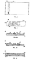
- the security device 10, Fig. 2 includes a carrier substrate 14, for example, formed as a thread or strip.
- carrier substrate 14 is made of a polyester, polyvinyl carbonate or polypropylene film on paper.
- the carrier substrate 14 can be a plastic film or metallized paper, or other type of material used in conventional security threads.
- the security device 10 includes graphic indicia 16 formed from a metallic/magnetic medium disposed on the carrier substrate 14.
- the graphic indicia 16 can be formed positively on the carrier substrate 14, i.e. the graphic indicia 16 is composed of the magnetic/metal medium.
- the graphic indicia 16 can also be formed in the reverse, i.e. the area 18 surrounding the graphic indicia 16 is composed of the magnetic/metallic medium.
- the magnetic/metallic security device 10 can also be formed with a combination of positive and reverse graphic indicia 16.
- the graphic indicia 16 can be printed as line work in which solid areas are printed in the desired shape or as halftone in which tiny dots are printed with varying spacing to vary the shading.
- the graphic indicia 16 are shown as alphanumeric characters, the present invention contemplates any type of symbol, design, shape or other graphic indicia.
- the method of making the exemplary security device 10, Figs. 3A and 3B, according to the present invention includes first applying a metallic layer 20 to the carrier substrate 14.
- the metallic layer 20 preferably includes aluminum that has been sputtered or vapor deposited on the carrier substrate 14.
- the metallic layer 20 can be a metallic foil or other type of metal applied to the carrier substrate 14.
- the magnetic chemical resist 22 includes film-forming chemical resisting resins containing ferromagnetic and or other magnetic pigments.
- the chemical resist include, but are not limited to, solvent based, water based or solid based, ultra violet (UV) or electron beam (EB) polymerized resin systems or other conventional chemical resist resins.
- the magnetic pigments include both hard and soft magnetic pigments, as will be described in greater detail below, typically ranging from about 200 oersteds to 10,000 oersteds.
- the magnetic chemical resist 22 resists the chemical attack and remains on the underlying metallic layer 20, arranged in the desired printed pattern.
- the magnetic chemical resist 22 is superimposed in substantially identical registration with at least a portion of the underlying metal layer 20, thereby providing both magnetic and metallic security features that are substantially indistinguishable in at least some areas of the security device 10.
- the magnetic chemical resist 22 thus acts both to resist chemical attack while etching the metallic layer 20 and to provide a magnetic security feature superimposed on the metallic security feature so as to be not easily identified.
- the graphical indicia 16 can be formed using other types of techniques including, but not limited to, lasers, mechanical scribing, abrading, and the like.
- a substrate containing a metallic layer is over-coated with a magnetic layer and subjected to a laser etching process. The laser etching selectively removes both the magnetic and metallic layers and forms the desired graphical indicia 16 having the magnetic security feature superimposed substantially identically over the metallic security feature.
- the present invention also contemplates using an additional coating or laminate 24, Fig. 3C, over the graphic indicia 16, on one or both sides.
- the additional layer 24 is used to help hide the security device 10 when embedded in paper and viewed with reflected light. In this case, however, the graphic indicia 16 created with the magnetic chemical resist will remain observable when viewed in transmitted light.
- the security device 10, Figs. 4A and 4B can be encoded with machine readable analog or digital data as well as provide authentication in multiple ways by using the various properties of the metallic and magnetic security features.
- Using one or more metallic and/or magnetic properties to authenticate the security device 10 or item 12 involves detecting whether or not the one or more properties are present on the security device 10.
- Using the one or more metallic and/or magnetic properties to encode as analog or digital data involves detecting and reading a combination of properties that represents a numerical code, e.g. in Binary-Coded Decimal (BCD) format, and decoding the code to determine the data represented thereby.
- BCD Binary-Coded Decimal
- the magnetic security feature is capable of authenticating an item or encoding data pertaining to the item in multiple ways.
- the graphic indicia 16 are formed as magnetic characters that can be read by conventional MICR detectors.
- the graphic indicia 16 is preferably formed as positive text.
- the magnetic chemical resist 22 includes a hard magnetic pigment that is capable of being magnetized in the same manner as a magnetic recording tape.
- graphic indicia 16, Fig. 4A is preferably formed as reverse text such that the magnetic chemical resist 22 including the hard magnetic pigment forms one or more magnetic tracks 23a, 23b.
- Authenticating data or other information can be written to and read from the magnetic track(s) 23a, 23b using conventional recording devices and read using conventional readers.
- the magnetic chemical resist 22 includes a soft magnetic that can be magnetized and holds a level of magnetism for a limited period of time depending upon the characteristics or properties of the soft magnetic.
- Using the soft magnetic allows the magnetic security feature to be further concealed because the magnetic properties will not be detected unless the soft magnetic is first magnetized.
- Soft magnetics typically have predetermined magnetic characteristics, such as a level of magnetism that they can achieve and rate of decay of magnetic charge. Soft magnetics can be used to provide authentication, by first magnetizing the magnetic/metallic security device 10 and then detecting the existence of the magnetic, the level of magnetism, or the rate of decay.
- the graphic indicia 16, Fig. 4B can further be used to encode data in a machine readable format.
- the graphic indicia segments 16a-16d can include two types of soft magnetic pigments, one having a fast decay rate 28a and one having a slow decay rate 28b, that represent binary integers encoding data in BCD format. Some segments 16a, 16c of the graphic indicia are printed with magnetics having a fast decay rate and other segments 16b, 16d of the graphic indicia are printed with magnetics having a slow decay rate. Data is thereby encoded in BCD format (0101) by providing a predetermined pattern of segments 16a-16d having the two different types of magnetic pigments.
- the encoded data can include verification data or other data pertaining to the item 12.
- different formulations of the magnetic chemical resist 22 having magnetic pigments with different magnetic properties or characteristics are printed onto the metallic layer 20 using multiple print stations, such as an offset printing press similar to the type used for multicolor printing.
- multiple print stations allows graphic indicia to be printed in any desired pattern using various combinations of magnetic chemical resists having various different magnetic properties.
- the present invention also contemplates simultaneously using the level of magnetism and decay rate properties of the soft magnetics, as well as a mixture of hard and soft magnetics to achieve any desired combination of magnetic characteristics or properties for authenticating an item or encoding data pertaining to an item.
- the exemplary embodiment described above refers to two different magnetic properties for encoding data in BCD format, any number of different properties can be used to encode data in other numerical formats.
- the metallic security feature can also provide authentication and/or encode data, e.g., by forming the segments 16a-16d with different lengths of metal representing data in BCD format (1100), as will be described in greater detail below.
- the device 30, Fig. 5, used to read the magnetic/metallic security features includes at least a detector/reader 34 for detecting one or more characteristics of the metal and/or magnetic layers and/or for reading the predetermined pattern formed by the metal and magnetic regions having different characteristics. After detecting the one or more characteristics, an authenticator 36 determines whether the security device is authentic. After reading the predetermined pattern, a decoder 38 decodes the data represented by the predetermined pattern.
- the device 30 further includes a magnetic charger 32 that charges the soft magnetic pigments prior to the reader 34 detecting the features of the magnetics, such as the existence of magnetics, the level of magnetization, the decay rate of the magnetic, or other detectable magnetic characteristics. Authentication can be made based upon whether the soft magnetic is present, whether the soft magnetic has a predetermined level of magnetization, or whether the soft magnetic has a predetermined decay rate.
- Decoding is performed by determining the pattern of the different magnetic characteristics read by the reader 34. For example, if the magnetic/metallic security device 10 shown in Fig. 4 is magnetized with the magnetizer 32, after a period of time, the segments 16b, 16d having a slower decay rate 28b will remain magnetized while the segments 16a, 16c having a faster decay rate 28a will no longer be magnetized.
- the reader 34 distinguishes the different magnetic properties and determines the predetermined pattern of magnetic properties. From the predetermined pattern of magnetic properties, the corresponding binary representation (0101) and the data represented thereby is decoded.
- the metallic security feature 40 includes a plurality of conductive regions 42 and non-conductive regions 44, such as a metallized polyester film having demetalized breaks, for example, formed using the chemical resist process described above.
- Each non-conductive region 44 is disposed between two of the conductive regions 42.
- the plurality of conductive regions 42 and non-conductive regions 44 form a predetermined pattern that represents a verification code or data encoded with the metallic security feature 40.
- Each conductive region 42 has one of at least two predetermined lengths, for example, long conductive regions 42a and short conductive regions 42b.
- Each predetermined length corresponds to a predetermined value so that the data can be determined by detecting the length of each conductive region 42 and determining a corresponding value.
- long conductive regions 42a correspond to a "1" and the short conductive regions 42b corresponds to a "0".
- the long and short conductive regions 42a, 42b are used to encode data in BCD format.
- the long and short conductive regions 42a, 42b are arranged in a predetermined series corresponding to the binary representation of the data to be encoded.
- the detector/reader 34 detects the length of each conductive region 42 in the series (e.g. long or short) and determines the corresponding binary representation. To provide authentication, the binary representation will be matched to a predefined verification code for an item 12. To read encoded data, the binary representation will be further decoded.
- the machine readable metallic security feature 40 allows encoded data to be easily varied by varying the sequence of the conductive regions 42a, 42b.
- the conductive regions can be formed according to various designs provided that they are conductive over one of the predetermined lengths, as will be described in greater detail below. Although only two lengths are discussed herein for simplification, the present invention contemplates using conductive regions of any number of different lengths for encoding data. For example, octal data can be encoded using eight (8) different length conduction regions.
- One method of reading and verifying the machine readable metallic security feature 40, Fig. 7, is by detecting the long and short conductive regions 42a, 42b using capacitive verification or detection, such as disclosed in U.S. Patent No. 5,419,424 issued to Harbaugh and incorporated herein by reference.
- capacitive verification methods the machine readable metallic security feature 40 is positioned proximate capacitive sensors 50 coupled to a verification device (not shown).
- the conductive regions 42 capacitively couple one sensor 52a to another sensor 52b.
- the conductive regions 42 of the machine readable encoded metallic security feature 40 are preferably formed from a metallic material, such as aluminum. Exemplary methods include, but are not limited to, forming the conductive regions 42 by metalization of a polyester film, hot stamped foil, and printing the conductive regions 42 with a metallic ink. The present invention contemplates other types of metallic material and methods of forming the metallic conductive regions and non-conductive breaks.
- the machine readable encoded metallic security feature 40 and the security device 10 in which it is used are preferably designed to allow minimal "stretching," for example, approximately 5% or less variation in length. Also, the detection of the lengths of the conductive regions 42a, 42b should account for the potential stretching of the security device and machine readable encoded metallic security feature 40, for example, by accounting for the potential percentage of change in length.
- each conductive region 42a, 42b includes indicia 46 disposed thereon.
- Indicia 46 printed or disposed on the conductive regions 42a, 42b can be used for providing an additional verification code or data or can be used to provide false patterns that deceive the counterfeiter and hide the true verification code.
- Such indicia includes alpha-numeric characters 46a, bar codes 46b, or other designs 46c.
- the indicia 46a-46c according to this embodiment is printed or disposed on the conductive regions 42a, 42b without breaking the conductivity of each conductive region 42a, 42b and without affecting the capacitive detection of the length of each conductive region 42a, 42b using capacitive sensors 52.
- the conductive regions 42 are formed as conductive indicia regions 62a-62c formed from a conductive material, for example, printed with metallic ink or formed with a chemical resist process.
- the conductive indicia regions 62a, 62c are established by having the individual characters or symbols 49a-49f of the indicia connected at contact points 48 and separated at the non-conductive regions 44.
- the conductive indicia regions 62a-62c thus have predetermined lengths and are arranged in predetermined patterns representing the encoded data to be detected, as discussed above.
- the conductive indicia regions 62a-62c include alpha-numeric characters as well as other symbols or characters used for providing an additional verification code or to provide false patterns that deceive the counterfeiter and hide the true encoded data.
- a further embodiment of the machine readable encoded metallic security feature 40c, Fig. 10, of the present invention includes conductive regions 42a-42c, such as narrow regions of metallic material, and non-conductive indicia regions 64a-64c breaking the conductivity between the conductive regions 42a-42c.
- conductive regions 42a-42c such as narrow regions of metallic material
- non-conductive indicia regions 64a-64c breaking the conductivity between the conductive regions 42a-42c.
- specific alpha-numeric characters or other symbols can be formed of non-conductive material or by a chemical resist or demetalizing process between the conductive regions 42a-42c to provide the "break" in conductivity.
- the alpha-numeric characters or other symbols constituting the non-conductive indicia regions 64a-64c further provide additional data or codes and false patterns that deceive the counterfeiter and hide the true encoded data.
- the present invention contemplates using the magnetic security features and metallic security features alone or together on a security device. Any number of the magnetic or metallic properties described above can be used individually or combined with other properties to provide authentication of an item, encode data pertaining to an item, or both.
- one or more security devices or threads 10, Fig. 11, can be provided in various locations on or embedded in a secure document or instrument 70.
- the one or more security devices 10 are also readable in various directions as well as right side up or upside down.
- the secure instrument 70 is formed by gluing the security device 10 between two half-weight layers of paper which are then laminated together.
- the security device 10 is preferably unlaminated so that any attempt to delaminate the instrument 70 and remove the security device 10 will cause the paper laminating adhesive to remove the metallic and/or magnetic security features and alter the security feature or encoded data.
- the instrument 70 is a ticket used for sporting events, concerts, theater, shows, lotteries, transportation, theme parks, fairs, and other events.
- the security device 10 in the ticket can be encoded with a predetermined authentication code or encoded data that can be read when the security instrument 70 is presented, e.g. upon admission to a particular event.
- one full code 72 appears in approximately 2.5 in.
- the security device of the present invention authenticates an item and/or is encoded with data pertaining to the item in numerous ways with one or more security features, such as metallic security features and magnetic security features that generally appear together as one single security feature.
- the security features and encoded data are thus more difficult to identify and reproduce.
- the method of making the security device using chemical etching and a magnetic chemical resist results in a magnetic security feature that is substantially indistinguishable from a metallic security feature.
- the method of printing graphic indicia using a magnetic chemical resist also facilitates the use of magnetic pigments having different magnetic characteristics or properties by printing different formulations of the magnetic chemical resist.
Landscapes
- Physics & Mathematics (AREA)
- Engineering & Computer Science (AREA)
- General Physics & Mathematics (AREA)
- Automation & Control Theory (AREA)
- Computer Security & Cryptography (AREA)
- Electromagnetism (AREA)
- Theoretical Computer Science (AREA)
- Credit Cards Or The Like (AREA)
Applications Claiming Priority (3)
| Application Number | Priority Date | Filing Date | Title |
|---|---|---|---|
| US6722897P | 1997-12-02 | 1997-12-02 | |
| US67228P | 1997-12-02 | ||
| EP19980962859 EP1034504B1 (fr) | 1997-12-02 | 1998-12-01 | Dispositif de securite comportant de multiples elements de securite et procede de fabrication correspondant |
Related Parent Applications (1)
| Application Number | Title | Priority Date | Filing Date |
|---|---|---|---|
| EP19980962859 Division EP1034504B1 (fr) | 1997-12-02 | 1998-12-01 | Dispositif de securite comportant de multiples elements de securite et procede de fabrication correspondant |
Publications (3)
| Publication Number | Publication Date |
|---|---|
| EP1310907A2 true EP1310907A2 (fr) | 2003-05-14 |
| EP1310907A3 EP1310907A3 (fr) | 2003-05-21 |
| EP1310907B1 EP1310907B1 (fr) | 2005-04-20 |
Family
ID=26152818
Family Applications (1)
| Application Number | Title | Priority Date | Filing Date |
|---|---|---|---|
| EP02028597A Revoked EP1310907B1 (fr) | 1997-12-02 | 1998-12-01 | Dispositif de securité comportant de multiples éléments de securité |
Country Status (1)
| Country | Link |
|---|---|
| EP (1) | EP1310907B1 (fr) |
Cited By (2)
| Publication number | Priority date | Publication date | Assignee | Title |
|---|---|---|---|---|
| WO2005001756A2 (fr) * | 2003-06-10 | 2005-01-06 | Crane & Co., Inc. | Dispositif de securite ameliore |
| AT500908A1 (de) * | 2003-06-17 | 2006-04-15 | Hueck Folien Gmbh | Sicherheitselement mit magnetischer codierung, verfahren und vorrichtung zu dessen herstellung und dessen verwendung |
Citations (5)
| Publication number | Priority date | Publication date | Assignee | Title |
|---|---|---|---|---|
| US5354099A (en) * | 1990-12-20 | 1994-10-11 | Gao Gesellschaft Fur Automation Und Organisation Mbh | Magnetic metallic safeguarding thread with negative writing |
| US5516153A (en) * | 1991-01-17 | 1996-05-14 | Gao Gesellschaft Fur Automation Und Organisation Mbh | Security document and a method for producing it |
| EP0748896A1 (fr) * | 1995-06-09 | 1996-12-18 | Giesecke & Devrient GmbH | Document de sécurité et son procédé de fabrication |
| US5614824A (en) * | 1995-05-15 | 1997-03-25 | Crane & Co., Inc. | Harmonic-based verifier device for a magnetic security thread having linear and non-linear ferromagnetic characteristics |
| DE19548528A1 (de) * | 1995-12-22 | 1997-06-26 | Giesecke & Devrient Gmbh | Sicherheitsdokument mit einem Sicherheitselement und Verfahren zu dessen Herstellung |
-
1998
- 1998-12-01 EP EP02028597A patent/EP1310907B1/fr not_active Revoked
Patent Citations (5)
| Publication number | Priority date | Publication date | Assignee | Title |
|---|---|---|---|---|
| US5354099A (en) * | 1990-12-20 | 1994-10-11 | Gao Gesellschaft Fur Automation Und Organisation Mbh | Magnetic metallic safeguarding thread with negative writing |
| US5516153A (en) * | 1991-01-17 | 1996-05-14 | Gao Gesellschaft Fur Automation Und Organisation Mbh | Security document and a method for producing it |
| US5614824A (en) * | 1995-05-15 | 1997-03-25 | Crane & Co., Inc. | Harmonic-based verifier device for a magnetic security thread having linear and non-linear ferromagnetic characteristics |
| EP0748896A1 (fr) * | 1995-06-09 | 1996-12-18 | Giesecke & Devrient GmbH | Document de sécurité et son procédé de fabrication |
| DE19548528A1 (de) * | 1995-12-22 | 1997-06-26 | Giesecke & Devrient Gmbh | Sicherheitsdokument mit einem Sicherheitselement und Verfahren zu dessen Herstellung |
Cited By (4)
| Publication number | Priority date | Publication date | Assignee | Title |
|---|---|---|---|---|
| WO2005001756A2 (fr) * | 2003-06-10 | 2005-01-06 | Crane & Co., Inc. | Dispositif de securite ameliore |
| WO2005001756A3 (fr) * | 2003-06-10 | 2005-05-12 | Crane & Co Inc | Dispositif de securite ameliore |
| US7703810B2 (en) | 2003-06-10 | 2010-04-27 | Crane & Co., Inc. | Security device |
| AT500908A1 (de) * | 2003-06-17 | 2006-04-15 | Hueck Folien Gmbh | Sicherheitselement mit magnetischer codierung, verfahren und vorrichtung zu dessen herstellung und dessen verwendung |
Also Published As
| Publication number | Publication date |
|---|---|
| EP1310907A3 (fr) | 2003-05-21 |
| EP1310907B1 (fr) | 2005-04-20 |
Similar Documents
| Publication | Publication Date | Title |
|---|---|---|
| EP1034504B1 (fr) | Dispositif de securite comportant de multiples elements de securite et procede de fabrication correspondant | |
| US6549131B1 (en) | Security device with foil camouflaged magnetic regions and methods of making same | |
| EP1397776B1 (fr) | Dispositif de securite comportant de multiples caracteristiques de detection de securite | |
| US20030164611A1 (en) | Antifalsification paper and security document produced therefrom | |
| CN111016494B (zh) | 防伪元件及防伪产品 | |
| EP1310907B1 (fr) | Dispositif de securité comportant de multiples éléments de securité | |
| JP2000113155A (ja) | Icカード | |
| MXPA00005343A (en) | Security device having multiple security features and method of making same | |
| CZ20002052A3 (cs) | Magnetický, kovový nebo magneticko-kovový ochranný prostředek mající vícenásobné ochranné charakteristické znaky, způsob jeho výroby a způsob ověřování jeho pravosti | |
| JPH07329464A (ja) | ロール状積層体 | |
| JPH0863741A (ja) | 情報記録媒体 | |
| JP2008062596A (ja) | 情報記録媒体 | |
| JP2000311222A (ja) | 磁気記録媒体及び真偽判定方法 | |
| JPH07329466A (ja) | 情報記録媒体 | |
| JPH0553001B2 (fr) | ||
| JPH09167219A (ja) | 情報記録媒体及びその真偽判定方法 | |
| GB2274620A (en) | Magnetic card with invisible oxide layer |
Legal Events
| Date | Code | Title | Description |
|---|---|---|---|
| PUAI | Public reference made under article 153(3) epc to a published international application that has entered the european phase |
Free format text: ORIGINAL CODE: 0009012 |
|
| PUAL | Search report despatched |
Free format text: ORIGINAL CODE: 0009013 |
|
| AC | Divisional application: reference to earlier application |
Ref document number: 1034504 Country of ref document: EP Kind code of ref document: P |
|
| AK | Designated contracting states |
Designated state(s): AT CH DE DK ES FI GB LI PT SE |
|
| AX | Request for extension of the european patent |
Extension state: SI |
|
| AK | Designated contracting states |
Designated state(s): AT CH DE DK ES FI GB LI PT SE |
|
| AX | Request for extension of the european patent |
Extension state: SI |
|
| 17P | Request for examination filed |
Effective date: 20031105 |
|
| 17Q | First examination report despatched |
Effective date: 20031211 |
|
| AKX | Designation fees paid |
Designated state(s): AT CH DE DK ES FI GB LI PT SE |
|
| GRAP | Despatch of communication of intention to grant a patent |
Free format text: ORIGINAL CODE: EPIDOSNIGR1 |
|
| GRAS | Grant fee paid |
Free format text: ORIGINAL CODE: EPIDOSNIGR3 |
|
| GRAA | (expected) grant |
Free format text: ORIGINAL CODE: 0009210 |
|
| AC | Divisional application: reference to earlier application |
Ref document number: 1034504 Country of ref document: EP Kind code of ref document: P |
|
| AK | Designated contracting states |
Kind code of ref document: B1 Designated state(s): AT CH DE DK ES FI GB LI PT SE |
|
| PG25 | Lapsed in a contracting state [announced via postgrant information from national office to epo] |
Ref country code: FI Free format text: LAPSE BECAUSE OF FAILURE TO SUBMIT A TRANSLATION OF THE DESCRIPTION OR TO PAY THE FEE WITHIN THE PRESCRIBED TIME-LIMIT Effective date: 20050420 Ref country code: AT Free format text: LAPSE BECAUSE OF FAILURE TO SUBMIT A TRANSLATION OF THE DESCRIPTION OR TO PAY THE FEE WITHIN THE PRESCRIBED TIME-LIMIT Effective date: 20050420 |
|
| REG | Reference to a national code |
Ref country code: GB Ref legal event code: FG4D |
|
| REG | Reference to a national code |
Ref country code: CH Ref legal event code: EP |
|
| REF | Corresponds to: |
Ref document number: 69829889 Country of ref document: DE Date of ref document: 20050525 Kind code of ref document: P |
|
| PG25 | Lapsed in a contracting state [announced via postgrant information from national office to epo] |
Ref country code: SE Free format text: LAPSE BECAUSE OF FAILURE TO SUBMIT A TRANSLATION OF THE DESCRIPTION OR TO PAY THE FEE WITHIN THE PRESCRIBED TIME-LIMIT Effective date: 20050720 Ref country code: DK Free format text: LAPSE BECAUSE OF FAILURE TO SUBMIT A TRANSLATION OF THE DESCRIPTION OR TO PAY THE FEE WITHIN THE PRESCRIBED TIME-LIMIT Effective date: 20050720 |
|
| REG | Reference to a national code |
Ref country code: CH Ref legal event code: NV Representative=s name: KIRKER & CIE SA |
|
| PG25 | Lapsed in a contracting state [announced via postgrant information from national office to epo] |
Ref country code: PT Free format text: LAPSE BECAUSE OF FAILURE TO SUBMIT A TRANSLATION OF THE DESCRIPTION OR TO PAY THE FEE WITHIN THE PRESCRIBED TIME-LIMIT Effective date: 20050920 |
|
| REG | Reference to a national code |
Ref country code: ES Ref legal event code: FG2A Ref document number: 2241947 Country of ref document: ES Kind code of ref document: T3 |
|
| PLBI | Opposition filed |
Free format text: ORIGINAL CODE: 0009260 |
|
| PLAX | Notice of opposition and request to file observation + time limit sent |
Free format text: ORIGINAL CODE: EPIDOSNOBS2 |
|
| 26 | Opposition filed |
Opponent name: GIESECKE & DEVRIENT GMBH Effective date: 20060119 |
|
| PLAF | Information modified related to communication of a notice of opposition and request to file observations + time limit |
Free format text: ORIGINAL CODE: EPIDOSCOBS2 |
|
| PLBB | Reply of patent proprietor to notice(s) of opposition received |
Free format text: ORIGINAL CODE: EPIDOSNOBS3 |
|
| RAP2 | Party data changed (patent owner data changed or rights of a patent transferred) |
Owner name: TECHNICAL GRAPHICS, INC. |
|
| PGFP | Annual fee paid to national office [announced via postgrant information from national office to epo] |
Ref country code: DE Payment date: 20061208 Year of fee payment: 9 |
|
| PGFP | Annual fee paid to national office [announced via postgrant information from national office to epo] |
Ref country code: GB Payment date: 20061218 Year of fee payment: 9 |
|
| PGFP | Annual fee paid to national office [announced via postgrant information from national office to epo] |
Ref country code: ES Payment date: 20070130 Year of fee payment: 9 |
|
| PGFP | Annual fee paid to national office [announced via postgrant information from national office to epo] |
Ref country code: CH Payment date: 20070306 Year of fee payment: 9 |
|
| PLAB | Opposition data, opponent's data or that of the opponent's representative modified |
Free format text: ORIGINAL CODE: 0009299OPPO |
|
| R26 | Opposition filed (corrected) |
Opponent name: GIESECKE & DEVRIENT GMBH Effective date: 20060119 |
|
| RDAE | Information deleted related to despatch of communication that patent is revoked |
Free format text: ORIGINAL CODE: EPIDOSDREV1 |
|
| RDAF | Communication despatched that patent is revoked |
Free format text: ORIGINAL CODE: EPIDOSNREV1 |
|
| RDAG | Patent revoked |
Free format text: ORIGINAL CODE: 0009271 |
|
| STAA | Information on the status of an ep patent application or granted ep patent |
Free format text: STATUS: PATENT REVOKED |
|
| 27W | Patent revoked |
Effective date: 20071011 |
|
| GBPR | Gb: patent revoked under art. 102 of the ep convention designating the uk as contracting state |
Free format text: 20071011 |
|
| REG | Reference to a national code |
Ref country code: CH Ref legal event code: PL |