EP1310388A2 - Niveauregelventil zum selbsttägigen Konstanthalten der Fahrzeughöhe eines Nutzfahrzeuges mit Luftfederung - Google Patents
Niveauregelventil zum selbsttägigen Konstanthalten der Fahrzeughöhe eines Nutzfahrzeuges mit Luftfederung Download PDFInfo
- Publication number
- EP1310388A2 EP1310388A2 EP02024348A EP02024348A EP1310388A2 EP 1310388 A2 EP1310388 A2 EP 1310388A2 EP 02024348 A EP02024348 A EP 02024348A EP 02024348 A EP02024348 A EP 02024348A EP 1310388 A2 EP1310388 A2 EP 1310388A2
- Authority
- EP
- European Patent Office
- Prior art keywords
- level control
- plate
- control valve
- valve element
- housing
- Prior art date
- Legal status (The legal status is an assumption and is not a legal conclusion. Google has not performed a legal analysis and makes no representation as to the accuracy of the status listed.)
- Granted
Links
- 239000000725 suspension Substances 0.000 title claims description 7
- 238000009423 ventilation Methods 0.000 claims description 15
- 238000010521 absorption reaction Methods 0.000 abstract 1
- 230000035939 shock Effects 0.000 abstract 1
- 230000033001 locomotion Effects 0.000 description 11
- 238000013022 venting Methods 0.000 description 6
- 239000004033 plastic Substances 0.000 description 3
- 238000007789 sealing Methods 0.000 description 3
- 229910010293 ceramic material Inorganic materials 0.000 description 2
- 238000004519 manufacturing process Methods 0.000 description 2
- 239000002184 metal Substances 0.000 description 2
- 238000012549 training Methods 0.000 description 2
- 239000000919 ceramic Substances 0.000 description 1
- 238000011161 development Methods 0.000 description 1
- 230000018109 developmental process Effects 0.000 description 1
- 238000006073 displacement reaction Methods 0.000 description 1
- 238000005553 drilling Methods 0.000 description 1
- 230000000694 effects Effects 0.000 description 1
- 210000003746 feather Anatomy 0.000 description 1
- 238000012545 processing Methods 0.000 description 1
- 230000007704 transition Effects 0.000 description 1
Images




Classifications
-
- B—PERFORMING OPERATIONS; TRANSPORTING
- B60—VEHICLES IN GENERAL
- B60G—VEHICLE SUSPENSION ARRANGEMENTS
- B60G17/00—Resilient suspensions having means for adjusting the spring or vibration-damper characteristics, for regulating the distance between a supporting surface and a sprung part of vehicle or for locking suspension during use to meet varying vehicular or surface conditions, e.g. due to speed or load
- B60G17/02—Spring characteristics, e.g. mechanical springs and mechanical adjusting means
- B60G17/04—Spring characteristics, e.g. mechanical springs and mechanical adjusting means fluid spring characteristics
- B60G17/052—Pneumatic spring characteristics
- B60G17/0523—Regulating distributors or valves for pneumatic springs
- B60G17/0525—Height adjusting or levelling valves
-
- B—PERFORMING OPERATIONS; TRANSPORTING
- B60—VEHICLES IN GENERAL
- B60G—VEHICLE SUSPENSION ARRANGEMENTS
- B60G2500/00—Indexing codes relating to the regulated action or device
- B60G2500/20—Spring action or springs
- B60G2500/202—Height or leveling valve for air-springs
- B60G2500/2022—Height or leveling valve for air-springs with valve seat actuation for selectively adjusting neutral height
Definitions
- the invention relates to a level control valve for automatic Keeping the vehicle height of a commercial vehicle with air suspension constant with those mentioned in the preamble of claim 1 Features.
- a level control valve is known from EP 0 556 086 B1 to automatically keep the vehicle height constant Commercial vehicle with air suspension known.
- the level control valve has a housing on which connections for cables are implemented are. A line is led from a compressed air supply. Another line leads to at least one air bag. Finally, a vent outlet is also provided.
- in the Inside the housing are two plate-shaped valve elements ceramic material provided under high plane parallelism lie flat against each other. The first valve element is fixed in the housing and has openings for the passage of compressed air. The second valve element is connected to an adjustment drive and via this adjustment drive in the housing and relative to the stationary first valve element pivotable.
- the two valve elements can be in one Ventilation position, a ventilation position and a final position to be spent. The final position corresponds to the intended vehicle height, which is independent of the respective The vehicle is always loaded. The setting a second vehicle height is not possible.
- DE 196 07 619 C1 is a conventionally constructed level control valve for automatically keeping the chassis height constant a commercial vehicle with air suspension known. It will be here Double valve body used, the one with an exhaust seat a hollow control rod an exhaust valve and with a housing-tight seat forms an inlet valve. Even on one such a level control valve is a ventilation position, a Bleed position and a final position for the air bellows possible.
- the tappet of the level control valve is over actuates an adjustment drive that rotates an eccentric shaft.
- the eccentric cam of the eccentric shaft moves a guide piece which in turn rests against the valve lifter.
- the invention has for its object a level control valve of the type described above, in which two plate-shaped valve elements are used and which is still adjustable to two vehicle heights.
- this is achieved in that the second plate-shaped valve element is movably mounted in the housing, and that an actuator for moving the second plate-shaped valve element from a first vehicle height corresponding position in a second vehicle height appropriate position and vice versa is provided.
- the invention is based on the idea of both plate-shaped Store the valve elements in the housing so that they can move.
- the mobility of the first plate-shaped valve element depends on the movements transmitted via the adjustment drive.
- the moveable Storage of the second plate-shaped valve element is the assigned to different vehicle heights. One determines first position a first vehicle height and a second position a second vehicle height, etc. It is one in some form Actuator provided an arbitrary Allows setting of the desired vehicle heights.
- Actuator provided an arbitrary Allows setting of the desired vehicle heights.
- a level control valve which can be of the two plate-shaped valve elements as a slide is formed, that the line connections despite this mobility can be arranged so that in each of the driving positions has a proper function of the level control valve results.
- the arrangement of the connecting channels and connection breakthroughs can be designed be so that in both or in all vehicle heights for example the ventilation of the air bellows via the same breakthroughs.
- the illustrated embodiments allow the connections for supply and ventilation also interchanged to prove. This has the advantage that the same level control valve either one or the other Vehicle side can be assigned.
- the two plate-shaped valve elements can be removed manufacture ceramic material. Such plate-shaped valve elements can then simply with high planarity of their areas manufactured and used sealing, so that the additional Arrangement of sealing elements between the two valve elements eliminated.
- the breakthroughs and channels in the two Valve elements can be easily moved during the Form or form the manufacture of the valve elements. A subsequent processing is omitted.
- the connecting channels or Openings in the two plate-shaped valve elements can also in their cross-sections and cross-sectional profiles can be designed and dimensioned accordingly simply so that an intended throttling effect or a quick one Venting can be effected in a simple manner.
- That new designed level control valve leaves the setting at least two vehicle heights. It clearly sets itself apart from that in the stand the way of arranging two level control valves side by side.
- the second vehicle height can be in can be made easily adjustable.
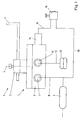
- the housing 1 shows a level control valve 1 with its housing 2.
- the housing 2 is expediently formed in several parts, around an interior to accommodate various valve elements to accomplish.
- the actuation shaft 3 is via a link lever 5 to the chassis connected while the housing 2 and thus the level control valve 1 is arranged on the vehicle body.
- the link lever 5 leads a rotational movement about the axis 6 of the actuating shaft 3.
- the Adjustment drive 4 transmits the movements between the chassis and vehicle body in the interior of the housing 2 of the level control valve 1.
- a connection 7 for a line 8 is provided from a storage container 9 the level control valve 1 is brought up.
- a connector 10 leads a line 11 to an air bag 12.
- actuating valve 14 which here is designed as a manually operated directional valve, one has its own vent connection and this via a line 15 to a control connection 16 on the housing 2 of the level control valve 1 is introduced.
- the actuating valve 14 can also can be realized in another way, for example as electrical controllable solenoid valve or as a tappet operated 3/2-way valve.
- the actuating valve 14 is always actuated if the second vehicle height is to be set. It will In the present case, at least two vehicle heights differ, whereby it It is ultimately irrelevant which of the vehicle heights is the first and which is referred to as the second height and which vehicle height is below the other vehicle height.
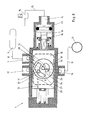
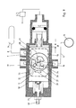
- the 2 and 3 is a first embodiment of the level control valve based on two perpendicular to each other Cuts made clear.
- the valve elements 17 and 18 are plate-like or disc-like and consist of Ceramic, plastic, metal or a ceramic-plastic combination. It is molded bodies, the surfaces with have high planarity.
- the valve elements 17 and 18 are located in such an area with high planarity. It it is expressly pointed out that here none Seals are required. The seal between the two Valve elements 17 and 18 is due to the large plane parallelism of the areas reached.
- the second is on the bottom Valve element 18 on the housing 2 of the level control valve.
- the Housing 2 is preferably made of plastic, but can also are made of metal. It is based on a precise editing of the Housing creating areas of high plane parallelism waived. Instead, seals are used here for sealing purposes 19 used, which also have the advantage that they bias the valve elements 17 and 18 against each other.
- a Eccentrically arranged cam 20 is provided, which on the attacks the first plate-shaped valve element 17 and thus the Rotary movement of the actuating shaft 3 on the valve element 17 transfers.
- the valve element 17 can be linear or rotating be movably provided. Depending on the connection designed between the cam 20 and the valve element 17 that the movement in question is possible. This happens, for example, when the rotary movement is transformed into a linear movement of the valve element 17 with a for reasons of clarity not shown slot.
- the valve element 17 according to the embodiment of FIGS. 2 and 3 becomes linear moves according to a double arrow 21.
- the second valve element 18 is now also movable in the Housing 2 of the level control valve 1 arranged and guided.
- the Movement happens according to double arrow 22 and is with the setting connected to the first and second vehicle heights.
- Setting the first or second vehicle height is in the housing 2 of the level control valve 1, a control piston 23 with a piston rod 24 provided, which via the actuating valve 14 and the Line 15 and the control connection 16 is acted upon.
- the unventilated position is secured by a spring 25.
- the second element element 18 has two positions can assume that are assigned to the two vehicle heights.
- On the piston rod 24 can be adjusted in a thread Stop 26 may be attached, when actuating the control piston 23 strikes the housing 2 and thus the stroke of the control piston limited. In this way, the second vehicle height and thus the relative position of the second plate-shaped Valve element 18 set.
- the piston rod 24 can otherwise strike freely against the valve element 18 or also be positively (Fig. 5) connected to the valve element 18.
- connection 27 leading to the atmosphere is provided.
- the air bellows are vented via this connection 27 12th
- the two valve elements 17 and 18 have openings, Channels, grooves or the like. Which is a complicated arrangement and have training. These channels are laid out in such a way that the required functions of the level control valve, namely venting the air bellows 12, venting the air bellows 12 as well as the final positions in the two vehicle heights, can be realized.
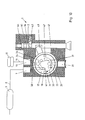
- From port 7 to which the Storage container 9 is connected leads in Fig. 3rd Channel 28 indicated by dashed lines within the housing 2 a bore 29 (Fig. 2), which is not shown in Fig. 3.
- the valve element 18 is penetrated by a channel 30, which on the bore 29 has a connection and on which the valve element 17 facing side ends in a circular opening 31 that is also indicated in dashed lines in FIG. 3. 2 and 3 it can be seen that the channel 30 or the opening 31 through the first valve element 17 is covered, so the supply here is completed.
- the level control valve of FIGS. 2 and 3 is in the final position at the first vehicle height.
- vent port 27 Channel 32 through the housing 2 below the second valve element 18.
- the second valve element 18 has one here another channel, not shown, which is similar to channel 30 is trained. This channel ends in a circular opening 33 on the top of the valve element 2. Also this opening 33, which thus leads to ventilation, is through the valve element 17 covered or closed.
- a channel 34 in the housing 2 leads to below the second Valve element 18. Similar to the already indicated channel 30 the second valve element 18 has a channel 35 which is in a circular opening 36 ends.
- the first plate-shaped valve element 17 has a groove-shaped on its underside Connecting channel 37, which is shown in both FIG. 2 and FIG. 3 is visible. The opening 36 lies within this connecting channel 37 so that the air bellows 12 are ventilated and closed are.
- Fig. 4 shows the level control valve according to FIGS. 2 and 3 in an enlarged view compared to FIG. 3 when set first vehicle height and during the ventilation of the air bellows 12. It can be seen that starting from the reservoir 9 via line 8 and connection 7 compressed air through the channel 28 and through the opening 31 into the connecting channel 37 of the valve element 17 passes. Still exists Connection via opening 36, channel 35 and channel 34 for connection 10 for line 11 to air bellows 12, so that compressed air ultimately leads to the air bellows 12 arrives. At the same time it can be seen that the opening 33 of the Channel 32 to the atmosphere is completed.
- Fig. 5 illustrates the venting position of this level control valve 1. It can be seen that the opening 31 of the channel 28 is cordoned off. In contrast, there is a connection between the air bellows 12 via line 11 and connection 10 in the Channel 34, the opening 35 via the connecting channel 37 Has connection to the opening 33 of the connecting channel 32, so that compressed air from the air bellows 12 escape into the atmosphere can.
- the piston rod 24 is form-fitting here connected to the second plate-shaped valve element 18.
- the Position shows the set first vehicle height, the Actuating valve 14, here in the form of a solenoid valve, is in its closed position.
- Fig. 6 illustrates an intermediate position, which during the Setting or reaching a second vehicle height of the elements is taken.
- control air passes via line 15 to control piston 23, so that its piston rod 24, the valve element 18 by the stroke 38 moves according to double arrow 22.
- the end position is indicated by Stop of the stop 26 reached on the housing 2. It is recognizable that the air bellows 12 to the vent connection 27 are connected so that ventilation of the Air bellows 12 takes place until the second (lower) Vehicle height is taken. Doing so will be different Pass through intermediate positions in which the articulation lever 5 has left its normal position. At the end of these movements a final position is established again, as shown in FIG. 3 shows.
- the first plate-shaped valve element 17 is circular here Disc formed. It is over the actuation shaft 3 driven in rotation, namely according to double arrow 39. Die Actuating shaft 3 and the valve element 17 can be in one piece here or be flanged directly to one another, since it on translating the rotary motion into a linear motion with respect to the valve element 17 no longer arrives.
- the second plate-shaped valve element 18 is still linear according to Double arrow 22 is provided movably around the two vehicle heights to make adjustable. As can be seen, there is the connecting channel 37 from two separate channel sections within the Valve element 17. The remaining channels, openings and connections are in turn arranged and housed as before has already been described.
- FIG. 8 shows the level control valve 1 according to FIG. 7 in the first set vehicle height in the ventilation position. It is recognizable that compressed air from the reservoir 9 via the Line 8 to port 7 and then through channel 28 to Opening 31 arrives. Via one part of the connecting channel 37 there is still connection to the opening 36 of the channel 34 and continue via connection 10 and line 11 to the air bellows 12. It can also be seen that the vent connection 28 via the channel 32 although connection to the Has opening 33. However, this opening 33 lies within one Part of the connecting channel 37 completed.
- Fig. 9 shows the level control valve of Figs. 7 and 8 in one Intermediate position to reach the second vehicle height.
- An adjusting screw 40 is provided here, which Function of the stop 26 fulfilled and an adjustment of second vehicle height allows.
- valve element 17 shows a further possible embodiment of the level control valve 1 with its housing 2.
- valve elements 17 and 18 as rotatable parts according to Double arrow 39 provided.
- the control of the valve element 17 can be done via the actuating shaft 3 as before has already been described.
- the valve element 18 has one Adjustment lever 41 with a manually actuated adjustment rod 42 works together.
- the Ball In the housing 2 is in association with the Adjustment rod 42 housed a ball catch 43, the Ball can optionally engage in three grooves 44, 45, 46 are assigned to the three vehicle heights. Channels 28, 32 and 34 with their openings 31, 33 and 36 are indicated.
- the connecting channel 37 also consists of two crescent-shaped attachments Grooves on the underside of the valve element 17.
- the adjustment rod 42 can be operated manually. It's easy to see that the operation also via remote control, for example Compressed air controlled or the like.
- Wells 47 in the top of the valve element 17 serve to connect to the Actuating shaft 3.
- FIG. 11 shows a further embodiment in which the valve element 17 is arranged rotatably while the valve element 18 is linear.
- the level control valve 1 also has a quick exhaust valve 48 which is shown in FIG Formed and housed in the housing. It is a 3/2-way valve 49 is provided, with which a control piston 50 with Compressed air can be vented from the reservoir 9.
- FIG. 11 shows the non-ventilated position of the control piston, the is secured by a return spring 51. It is recognizable that different on the piston rod of the control piston Seals are provided at associated intervals with Collaborative extensions work together.
- the vent connection is also 27 separated from the connector 10.
- the control piston 50 with compressed air via the 3/2-way valve 49 acted upon.
- the channel 34 of the Port 10 separated and with the vent port 27 directly connected.
- Fig. 12 shows a similar embodiment of the level control valve 1 like Fig. 11. Again, there is a quick exhaust valve 48 provided, which, however, is slightly different from the Embodiment according to FIG. 11 is formed.
- a separate ventilation duct 52 is provided, via which when the control piston 50 is actuated, the ventilation of the air bellows 12 into the atmosphere. It's a position here shown that set the transition to the second Vehicle height corresponds.
- Fig. 13 The embodiment shown in Fig. 13 is similar in some Regarding the embodiment of FIGS. 2-6. It is a special one trained actuating valve 14 is provided, which as Switchover valve for the two vehicle heights is used. on the one On the side, the control piston 23 is provided for the first vehicle height. On the other side there is a control piston 53 with piston rod 54, which is assigned to the second vehicle height is. The two control pistons 23 and 53 are optionally or alternately operated and shift the second plate-shaped Valve element 18 in the longitudinal direction. The first plate-shaped Valve element 17 is also linear.
- Level control valve 1 finally shows a further embodiment of the Level control valve 1.
- the peculiarity is that the first plate-shaped valve element 17 according to double arrow 21 is guided linearly in the housing 2.
- the valve element 18 via the control piston 23 according to the double arrow 22 moved linearly and parallel to the double arrow 21.
- Another control piston 53 optionally serves to displace the valve element 18 in a direction perpendicular to the double arrow 22, with which a third vehicle height is adjustable.
Landscapes
- Engineering & Computer Science (AREA)
- Mechanical Engineering (AREA)
- Vehicle Body Suspensions (AREA)
- Fluid-Damping Devices (AREA)
Abstract
Description
- Fig. 1
- die schematische Darstellung eines Niveauregelventils in Verbindung mit den angeschlossenen Elementen,
- Fig. 2
- einen Schnitt durch eine erste Ausführungsform des Niveauregelventils gemäß der Linie II-II in Fig. 3,
- Fig. 3
- einen Horizontalschnitt durch das Niveauregelventil gemäß Fig. 2,
- Fig. 4
- eine ähnliche Darstellung wie Fig. 3 mit dem Niveauregelventil in der Stellung Belüften,
- Fig. 5
- eine ähnliche Darstellung wie Fig. 3 mit dem Niveauregelventil in der Stellung Entlüften,
- Fig. 6
- eine ähnliche Darstellung des Niveauregelventils gemäß den Fig. 3-5, jedoch während des Verstellens in eine zweite Fahrzeughöhe,
- Fig. 7
- eine ähnliche Schnittdarstellung, jedoch bei einer anderen Ausführungsform des Niveauregelventils in Abschlussstellung in der ersten Fahrzeughöhe,
- Fig. 8
- das Niveauregelventil gemäß Fig. 7 in der Stellung Belüften bei der ersten eingestellten Fahrzeughöhe,
- Fig. 9
- das Niveauregelventil der Fig. 7 und 8 zu Beginn des Einstellens der zweiten Fahrzeughöhe,
- Fig. 10
- eine Schnittdarstellung einer weiteren Ausführungsform des Niveauregelventils, eingestellt auf eine dritte Fahrzeughöhe,
- Fig. 11
- einen Schnitt durch ein Niveauregelventil ähnlich der Darstellung der Fig. 2, jedoch mit einem Schnellentlüftungsventil,
- Fig. 12
- eine ähnliche Darstellung eines Niveauregelventils wie Fig. 11, jedoch eingestellt auf eine zweite Fahrzeughöhe und eine andere Ausführungsform des Schnellentlüftungsventils,
- Fig. 13
- eine Schnittdarstellung eines Niveauregelventils, bei dem die beiden Fahrzeughöhen jeweils einstellbar sind,
- Fig. 14
- einen Schnitt durch ein Niveauregelventil ähnlich der Schnittdarstellung der Fig. 3, bei dem die beiden plattenförmigen Ventilelemente rechtwinklig zu einander bewegbar angeordnet sind, und
- Fig. 15
- eine Schnittdarstellung einer weiteren Ausführungsform des Niveauregelventils mit einer Einstellmöglichkeit auf drei unterschiedliche Fahrzeughöhen.
- 1 -
- Niveauregelventil
- 2 -
- Gehäuse
- 3 -
- Betätigungswelle
- 4 -
- Verstelltrieb
- 5 -
- Anlenkhebel
- 6 -
- Achse
- 7 -
- Anschluss
- 8 -
- Leitung
- 9 -
- Vorratsbehälter
- 10 -
- Anschluss
- 11 -
- Leitung
- 12 -
- Luftfederbalg
- 13 -
- Leitung
- 14 -
- Betätigungsventil
- 15 -
- Leitung
- 16 -
- Steueranschluss
- 17 -
- Ventilelement
- 18 -
- Ventilelement
- 19 -
- Dichtung
- 20 -
- Nocken
- 21 -
- Doppelpfeil
- 22 -
- Doppelpfeil
- 23 -
- Steuerkolben
- 24 -
- Kolbenstange
- 25 -
- Feder
- 26 -
- Anschlag
- 27 -
- Entlüftungsanschluss
- 28 -
- Kanal
- 29 -
- Bohrung
- 30 -
- Kanal
- 31 -
- Öffnung
- 32 -
- Kanal
- 33 -
- Öffnung
- 34 -
- Kanal
- 35 -
- Kanal
- 36 -
- Öffnung
- 37 -
- Verbindungskanal
- 38 -
- Hub
- 39 -
- Doppelpfeil
- 40 -
- Einstellschraube
- 41 -
- Verstellhebel
- 42 -
- Verstellstange
- 43 -
- Kugelverrastung
- 44 -
- Nut
- 45 -
- Nut
- 46 -
- Nut
- 47 -
- Vertiefung
- 48 -
- Schnellentlüftungsventil
- 49 -
- 3/2-Wegeventil
- 50 -
- Steuerkolben
- 51 -
- Rückführfeder
- 52 -
- Entlüftungskanal
- 53 -
- Steuerkolben
- 54 -
- Kolbenstange
Claims (12)
- Niveauregelventil (1) zum selbsttätigen Konstanthalten der Fahrzeughöhe eines Nutzfahrzeuges mit Luftfederung, mit einem Gehäuse (2), an dem Anschlüsse (7, 10, 27) für Leitungen (8, 11) von einem Druckluftvorrat und zu mindestens einem Luftfederbalg (12) sowie zur Atmosphäre vorgesehen sind und in dem mindestens zwei plattenförmige Ventilelemente (17, 18) vorgesehen sind, die unter Vorspannung dichtend flächig aneinanderliegen und Verbindungskanäle bildende Durchbrechungen aufweisen, wobei das eine plattenförmige Ventilelement (17) über einen die Fahrzeughöhe abtastenden Verstelltrieb (4) im Gehäuse (2) so beweglich gelagert ist, dass wahlweise eine Belüftungsstellung, eine Entlüftungsstellung und eine Abschlussstellung möglich sind, dadurch gekennzeichnet, dass auch das zweite plattenförmige Ventilelement (18) im Gehäuse (2) beweglich gelagert ist, und dass eine Betätigungseinrichtung (14, 23, 24, 42, 53, 54) zum Bewegen des zweiten plattenförmigen Ventilelements (18) aus einer einer ersten Fahrzeughöhe entsprechenden Stellung in eine einer zweiten Fahrzeughöhe entsprechende Stellung und umgekehrt vorgesehen ist.
- Niveauregelventil nach Anspruch 1, dadurch gekennzeichnet, dass das erste und/oder das zweite plattenförmige Ventilelement (17, 18) im Gehäuse (2) linear geführt ist.
- Niveauregelventil nach Anspruch 1, dadurch gekennzeichnet, dass das erste und/oder das zweite plattenförmige Ventilelement (17, 18) im Gehäuse (2) drehbar geführt ist.
- Niveauregelventil nach einem der Ansprüche 1 bis 3, dadurch gekennzeichnet, dass die beiden den zwei Fahrzeughöhen zugeordneten Stellungen des zweiten plattenförmigen Ventilelements (18) kraft- und/oder formschlüssig gesichert sind.
- Niveauregelventil nach Anspruch 1, dadurch gekennzeichnet, dass die Betätigungseinrichtung als manuell betätigbarer Hebel (42) ausgebildet ist.
- Niveauregelventil nach Anspruch 1, dadurch gekennzeichnet, dass die Betätigungseinrichtung einen Steuerkolben (23) mit Kolbenstange (24) aufweist.
- Niveauregelventil nach Anspruch 6, dadurch gekennzeichnet, dass die Kolbenstange (24) mit dem zweiten plattenförmigen Ventilelement (18) verbunden ist.
- Niveauregelventil nach Anspruch 1, dadurch gekennzeichnet, dass das zweite plattenförmige Ventilelement (18) im Gehäuse (2) gegen eine Feder (25) vorgespannt gelagert ist.
- Niveauregelventil nach Anspruch 1, dadurch gekennzeichnet, dass zur genauen Einstellung der ersten und/oder der zweiten Fahrzeughöhe ein einstellbarer Anschlag (26) vorgesehen ist.
- Niveauregelventil nach Anspruch 1, dadurch gekennzeichnet, dass das erste plattenförmige Ventilelement (17) einseitig einen U-förmigen Verbindungskanal (37) aufweist.
- Niveauregelventil nach Anspruch 1, dadurch gekennzeichnet, dass das erste plattenförmige Ventilelement (18) einseitig zwei voneinander getrennte Verbindungskanäle (37) aufweist.
- Niveauregelventil nach Anspruch 1, dadurch gekennzeichnet, dass das Niveauregelventil ein willkürlich schaltbares Schnellentlüftungsventil (48) aufweist, das unabhängig von der eingestellten Fahrzeughöhe eine schnelle Entlüftung der Luftfederbälge (12) ermöglicht.
Applications Claiming Priority (2)
| Application Number | Priority Date | Filing Date | Title |
|---|---|---|---|
| DE2001154778 DE10154778C1 (de) | 2001-11-08 | 2001-11-08 | Niveauregelventil zum selbsttätigen Konstanthalten der Fahrzeughöhe eines Nutzfahrzeuges mit Luftfederung |
| DE10154778 | 2001-11-08 |
Publications (3)
| Publication Number | Publication Date |
|---|---|
| EP1310388A2 true EP1310388A2 (de) | 2003-05-14 |
| EP1310388A3 EP1310388A3 (de) | 2003-10-08 |
| EP1310388B1 EP1310388B1 (de) | 2008-06-25 |
Family
ID=7704974
Family Applications (1)
| Application Number | Title | Priority Date | Filing Date |
|---|---|---|---|
| EP20020024348 Expired - Lifetime EP1310388B1 (de) | 2001-11-08 | 2002-11-02 | Niveauregelventil zum selbsttägigen Konstanthalten der Fahrzeughöhe eines Nutzfahrzeuges mit Luftfederung |
Country Status (3)
| Country | Link |
|---|---|
| EP (1) | EP1310388B1 (de) |
| DE (2) | DE10154778C1 (de) |
| ES (1) | ES2307698T3 (de) |
Cited By (1)
| Publication number | Priority date | Publication date | Assignee | Title |
|---|---|---|---|---|
| CN113085469A (zh) * | 2020-01-08 | 2021-07-09 | 威伯科欧洲有限责任公司 | 用于商用车辆的气动悬架系统的悬架控制阀装置 |
Families Citing this family (2)
| Publication number | Priority date | Publication date | Assignee | Title |
|---|---|---|---|---|
| DE102009007691B3 (de) † | 2009-02-05 | 2010-08-05 | Knorr-Bremse Systeme für Nutzfahrzeuge GmbH | Niveauregelventil mit druckbelasteter Ventilscheibe |
| DE102014103842B4 (de) * | 2014-03-20 | 2018-01-11 | Knorr-Bremse Systeme für Nutzfahrzeuge GmbH | Vorrichtung zur Steuerung von pneumatischen Einrichtungen eines Anhängers für ein Nutzfahrzeug |
Citations (2)
| Publication number | Priority date | Publication date | Assignee | Title |
|---|---|---|---|---|
| EP0556086B1 (de) | 1992-02-14 | 1996-07-17 | WABCO France | Ventil zum Auslassen und Einlassen eines Fluidums, insbesondere ein Niveauregelventil für eine Luftfederung und ein, ein solches Ventil benützendes, Federungssystem |
| DE19607619C1 (de) | 1996-02-29 | 1997-07-31 | Grau Gmbh | Niveauregelventil zum selbsttätigen Konstanthalten der Fahrzeughöhe eines Nutzfahrzeuges mit Luftfederung |
Family Cites Families (5)
| Publication number | Priority date | Publication date | Assignee | Title |
|---|---|---|---|---|
| US2954987A (en) * | 1958-11-28 | 1960-10-04 | Gen Motors Corp | Two-position air suspension control valve |
| US5161817A (en) * | 1990-10-16 | 1992-11-10 | Imo Industries Inc. | Fluid-operated leveling valve systems |
| US5335695A (en) * | 1993-06-16 | 1994-08-09 | Nai Neway, Inc. | Height control valve with adjustable spool |
| DE4414868C1 (de) * | 1994-04-28 | 1995-05-11 | Grau Gmbh | Steueranlage zum willkürlichen Heben und Senken des Fahrzeugaufbaus von luftgefederten Fahrzeugen |
| US5651555A (en) * | 1995-11-13 | 1997-07-29 | Barksdale, Inc. | Fluid-operated leveling valve systems |
-
2001
- 2001-11-08 DE DE2001154778 patent/DE10154778C1/de not_active Expired - Fee Related
-
2002
- 2002-11-02 EP EP20020024348 patent/EP1310388B1/de not_active Expired - Lifetime
- 2002-11-02 ES ES02024348T patent/ES2307698T3/es not_active Expired - Lifetime
- 2002-11-02 DE DE50212405T patent/DE50212405D1/de not_active Expired - Lifetime
Patent Citations (2)
| Publication number | Priority date | Publication date | Assignee | Title |
|---|---|---|---|---|
| EP0556086B1 (de) | 1992-02-14 | 1996-07-17 | WABCO France | Ventil zum Auslassen und Einlassen eines Fluidums, insbesondere ein Niveauregelventil für eine Luftfederung und ein, ein solches Ventil benützendes, Federungssystem |
| DE19607619C1 (de) | 1996-02-29 | 1997-07-31 | Grau Gmbh | Niveauregelventil zum selbsttätigen Konstanthalten der Fahrzeughöhe eines Nutzfahrzeuges mit Luftfederung |
Cited By (3)
| Publication number | Priority date | Publication date | Assignee | Title |
|---|---|---|---|---|
| CN113085469A (zh) * | 2020-01-08 | 2021-07-09 | 威伯科欧洲有限责任公司 | 用于商用车辆的气动悬架系统的悬架控制阀装置 |
| US11390132B2 (en) | 2020-01-08 | 2022-07-19 | Wabco Europe Bvba | Suspension control valve arrangement for a pneumatic suspension system of a commercial vehicle |
| CN113085469B (zh) * | 2020-01-08 | 2023-12-22 | 采埃孚商用车系统欧洲有限公司 | 用于商用车辆的气动悬架系统的悬架控制阀装置 |
Also Published As
| Publication number | Publication date |
|---|---|
| DE50212405D1 (de) | 2008-08-07 |
| ES2307698T3 (es) | 2008-12-01 |
| EP1310388B1 (de) | 2008-06-25 |
| EP1310388A3 (de) | 2003-10-08 |
| DE10154778C1 (de) | 2002-12-12 |
Similar Documents
| Publication | Publication Date | Title |
|---|---|---|
| EP2008864B1 (de) | Fahrzeugsitz mit Schieberventil | |
| DE19720100C2 (de) | Linearstellglied | |
| DE3925470C2 (de) | Stoßdämpfer mit einer Dämpfungsventilkonstruktion mit einer innerhalb eines großen Bereichs variablen Dämpfungscharakteristik | |
| DE3924166C1 (en) | Hydraulic vibration damper with valved piston - has changeover control rod with several surface recesses with different widths | |
| CH658109A5 (de) | 5/2-wegeventil in schieberbauart fuer die druckmittelversorgung eines servomotors. | |
| DE3446810C1 (de) | Niveauregelventil mit Hoehenbegrenzung | |
| DE4028887C2 (de) | Hydraulische Steuereinrichtung | |
| DE4103356C1 (en) | Hydraulic vibration damper with valved piston - has control body active face of several, angularly-set, individual faces | |
| DE10154778C1 (de) | Niveauregelventil zum selbsttätigen Konstanthalten der Fahrzeughöhe eines Nutzfahrzeuges mit Luftfederung | |
| AT391178B (de) | 5/3-wege-ventileinheit | |
| DE10014906B4 (de) | Mehrwegeventil (Deckelbefestigung) | |
| DE19537417C2 (de) | Hydraulischer Stellantrieb | |
| DE102017003400A1 (de) | Dreistellungsaktuator für ein automatisiertes Schaltgetriebe | |
| DE19625131C2 (de) | Druckmittelbetriebener Scheibenwischermotor | |
| DE202004004861U1 (de) | Handhilfsbetätigbares pneumatisches Mehrwegeventil | |
| DE3306613A1 (de) | Pneumatischer drehantrieb | |
| DE19912906B4 (de) | Hydraulischer Stellantrieb | |
| DE3815855C1 (de) | ||
| DE2806929C2 (de) | Fluidbetätigter Servomotor mit Nachlaufsteuerung | |
| DE8717630U1 (de) | Doppeltwirkender Druckmittelzylinder | |
| DE3315313A1 (de) | Steuerventil mit totmannschaltung | |
| DE3445594C2 (de) | ||
| DE1176000B (de) | Mit Druckmittel arbeitende Hilfskraftschalt-vorrichtung fuer Kraftfahrzeug-Wechselgetriebe | |
| EP2818618A1 (de) | Vorrichtung zur Regelung der Schließfolge einer zweiflügeligen Drehtüranlage | |
| DE4123718A1 (de) | Hydraulisches sperrventil |
Legal Events
| Date | Code | Title | Description |
|---|---|---|---|
| PUAI | Public reference made under article 153(3) epc to a published international application that has entered the european phase |
Free format text: ORIGINAL CODE: 0009012 |
|
| AK | Designated contracting states |
Designated state(s): AT BE BG CH CY CZ DE DK EE ES FI FR GB GR IE IT LI LU MC NL PT SE SK TR |
|
| AX | Request for extension of the european patent |
Extension state: AL LT LV MK RO SI |
|
| PUAL | Search report despatched |
Free format text: ORIGINAL CODE: 0009013 |
|
| AK | Designated contracting states |
Kind code of ref document: A3 Designated state(s): AT BE BG CH CY CZ DE DK EE ES FI FR GB GR IE IT LI LU MC NL PT SE SK TR |
|
| AX | Request for extension of the european patent |
Extension state: AL LT LV MK RO SI |
|
| 17P | Request for examination filed |
Effective date: 20031022 |
|
| AKX | Designation fees paid |
Designated state(s): DE ES FR IT |
|
| GRAP | Despatch of communication of intention to grant a patent |
Free format text: ORIGINAL CODE: EPIDOSNIGR1 |
|
| GRAC | Information related to communication of intention to grant a patent modified |
Free format text: ORIGINAL CODE: EPIDOSCIGR1 |
|
| GRAS | Grant fee paid |
Free format text: ORIGINAL CODE: EPIDOSNIGR3 |
|
| GRAA | (expected) grant |
Free format text: ORIGINAL CODE: 0009210 |
|
| AK | Designated contracting states |
Kind code of ref document: B1 Designated state(s): DE ES FR IT |
|
| REF | Corresponds to: |
Ref document number: 50212405 Country of ref document: DE Date of ref document: 20080807 Kind code of ref document: P |
|
| REG | Reference to a national code |
Ref country code: ES Ref legal event code: FG2A Ref document number: 2307698 Country of ref document: ES Kind code of ref document: T3 |
|
| PLBE | No opposition filed within time limit |
Free format text: ORIGINAL CODE: 0009261 |
|
| STAA | Information on the status of an ep patent application or granted ep patent |
Free format text: STATUS: NO OPPOSITION FILED WITHIN TIME LIMIT |
|
| 26N | No opposition filed |
Effective date: 20090326 |
|
| PG25 | Lapsed in a contracting state [announced via postgrant information from national office to epo] |
Ref country code: IT Free format text: LAPSE BECAUSE OF NON-PAYMENT OF DUE FEES Effective date: 20081102 |
|
| REG | Reference to a national code |
Ref country code: ES Ref legal event code: FD2A Effective date: 20081103 |
|
| PG25 | Lapsed in a contracting state [announced via postgrant information from national office to epo] |
Ref country code: ES Free format text: LAPSE BECAUSE OF NON-PAYMENT OF DUE FEES Effective date: 20081103 |
|
| PGFP | Annual fee paid to national office [announced via postgrant information from national office to epo] |
Ref country code: FR Payment date: 20101130 Year of fee payment: 9 |
|
| PGFP | Annual fee paid to national office [announced via postgrant information from national office to epo] |
Ref country code: DE Payment date: 20101111 Year of fee payment: 9 |
|
| REG | Reference to a national code |
Ref country code: FR Ref legal event code: ST Effective date: 20120731 |
|
| PG25 | Lapsed in a contracting state [announced via postgrant information from national office to epo] |
Ref country code: FR Free format text: LAPSE BECAUSE OF NON-PAYMENT OF DUE FEES Effective date: 20111130 |
|
| REG | Reference to a national code |
Ref country code: DE Ref legal event code: R119 Ref document number: 50212405 Country of ref document: DE Effective date: 20130601 |
|
| PG25 | Lapsed in a contracting state [announced via postgrant information from national office to epo] |
Ref country code: DE Free format text: LAPSE BECAUSE OF NON-PAYMENT OF DUE FEES Effective date: 20130601 |