EP1310145A2 - Bodenbearbeitungsgerät mit mehreren Geräteeinheiten - Google Patents
Bodenbearbeitungsgerät mit mehreren Geräteeinheiten Download PDFInfo
- Publication number
- EP1310145A2 EP1310145A2 EP02024315A EP02024315A EP1310145A2 EP 1310145 A2 EP1310145 A2 EP 1310145A2 EP 02024315 A EP02024315 A EP 02024315A EP 02024315 A EP02024315 A EP 02024315A EP 1310145 A2 EP1310145 A2 EP 1310145A2
- Authority
- EP
- European Patent Office
- Prior art keywords
- bolt
- rod
- soil cultivation
- actuating
- units
- Prior art date
- Legal status (The legal status is an assumption and is not a legal conclusion. Google has not performed a legal analysis and makes no representation as to the accuracy of the status listed.)
- Withdrawn
Links
Images


Classifications
-
- A—HUMAN NECESSITIES
- A01—AGRICULTURE; FORESTRY; ANIMAL HUSBANDRY; HUNTING; TRAPPING; FISHING
- A01B—SOIL WORKING IN AGRICULTURE OR FORESTRY; PARTS, DETAILS, OR ACCESSORIES OF AGRICULTURAL MACHINES OR IMPLEMENTS, IN GENERAL
- A01B71/00—Construction or arrangement of setting or adjusting mechanisms, of implement or tool drive or of power take-off; Means for protecting parts against dust, or the like; Adapting machine elements to or for agricultural purposes
- A01B71/02—Setting or adjusting mechanisms
-
- A—HUMAN NECESSITIES
- A01—AGRICULTURE; FORESTRY; ANIMAL HUSBANDRY; HUNTING; TRAPPING; FISHING
- A01B—SOIL WORKING IN AGRICULTURE OR FORESTRY; PARTS, DETAILS, OR ACCESSORIES OF AGRICULTURAL MACHINES OR IMPLEMENTS, IN GENERAL
- A01B63/00—Lifting or adjusting devices or arrangements for agricultural machines or implements
- A01B63/14—Lifting or adjusting devices or arrangements for agricultural machines or implements for implements drawn by animals or tractors
- A01B63/24—Tools or tool-holders adjustable relatively to the frame
- A01B63/26—Tools or tool-holders adjustable relatively to the frame by man-power
Definitions
- the invention relates to a tillage implement several device units according to the preamble of Claim 1.
- Such a tillage implement is for example in DE-198 17 544 A1.
- This Soil cultivation device is the adjustment device between the device units and the subordinate ones Machining organs from the side by moving one Adjustable rod with stair-shaped adjustment elements.
- the invention has for its object a simple to create a remote control device.
- the actuators are designed as eccentric discs are that the eccentric discs of a device unit on one rotatably mounted rod are arranged so that the Rod is assigned a fixation device.
- a simple fixation of the eccentric washers achieved that the fixing device as a perforated disc is formed and cooperates with a bolt.
- the actuating device is designed as a displaceable bolt, that of the outside of the tillage implement bolts located at a distance from the exterior of the Soil cultivator actuated rod is arranged.
- the bolt can move over the rod the respective hole in a row of holes of an adjusting element be used from the outside.
- the bolt in limited scope is movably attached to the rod. It has been shown here that it is advantageous that the Movement of the bolt about 4 to 10 degrees, preferably 6 Degrees to the bar.
- Fig. 1 shows a perspective view of the Assignment of a device unit 1 with a subordinate Packer roller 2 of a soil tillage implement in perspective and schematic representation. It is only the right side of the soil tillage implement is shown, this tillage implement consisting of two to each other collapsible parts.
- the device unit 1 can as Rotary harrow or rotary cultivator that is motor-driven is, be trained. Behind the unit 1 is the Roller 2, of which only the upper crossbar 3 and the support arms 4 are arranged. The following description also applies to a depth or height adjustment of a Leveling bar or another subordinate Processing organ.
- Connection points 6 for the support arms 4 of a trailing one Roller 2 arranged on the carrier 5 of the device unit 1 .
- the Eccentric discs 7 having actuator 8 is provided.
- the roller 2 is with two support arms 4 on the support element 6 Device unit 1 articulated.
- Each support arm 4 is one of two Partial eccentric discs 7, 7 'existing actuating device 8 assigned that rotatably with each other via a rod 10 are connected.
- the Device unit 1 designed as a perforated disc 11 Fixing device arranged. This fixing washer 11 interacts with a bolt 12, each by a Hole of the perforated disc 11 is inserted. This bolt 12 acts then together with the coupling piece of the support element 6.
- the Eccentric discs 7 have notches 14 on their circumference on.
- notches 14 each act corresponding to the setting with one on the Support arm 4 arranged elevation 15 together.
- the Eccentric disc 7 for shallower working depths acts with the upper notches 14 forming Bolts 15 'together while the eccentric discs 8' 'for greater working depths with the lower bolt 15 '', which is the Survey 15 forms interact.
- the lower bolts 15 ⁇ protrude from the support arm 4 on the other side, since the Support arms 4 are identical.
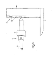
- the actuating device 16 as a displaceable bolt 17 formed the in different holes 19 of the Junction 20, which has a row of holes 21 can be used is.
- the bolt 17 is one of Actuated rod 22 assigned to the outer area.
- the rod 22 is about halfway between the outside of the Unit 1 and the bolt 17 in one Sliding guide element 23, which on the device unit or is arranged on the trailing roller 2 for inserting the Bolt 17 guided and supported in a bore 18.
- the Bolt 17 is movable to a limited extent on rod 22 attached.
- the mobility of the bolt 17 is approximately 4 to 5 degrees, preferably 6 degrees from the bar.
- the Bolt 17 is in the embodiment as an eccentric bolt formed, so fewer holes 18 in the Junction 20 adjustment devices may be provided to nevertheless by appropriately twisted insertion of the Eccentric bolt 17 to a finely graduated setting to reach.
- After insertion of the eccentric bolt 17 in the desired hole to the The rod will ensure the desired depth setting 22 inserted into the fixing element 24.
- the locking element formed as a ring 25 attached.
- the securing element 25 comes behind the Fixing element 24 in the fixing element 24 is the Plug trained fuse element 26 on the Fixing element 24 attached so that the bolt is secured is and cannot migrate out of hole 18.
Landscapes
- Life Sciences & Earth Sciences (AREA)
- Engineering & Computer Science (AREA)
- Mechanical Engineering (AREA)
- Soil Sciences (AREA)
- Environmental Sciences (AREA)
- Zoology (AREA)
- Soil Working Implements (AREA)
Abstract
Description
- Fig. 1
- die Stelleinrichtung eines Bodenbearbeitungsgerätes in perspektivischer und schematischer Darstellungsweise und
- Fig. 2
- eine weitere Stelleinrichtung eines Bodenbearbeitungsgerätes in perspektivischer und schematischer Darstellungsweise.
Claims (8)
- Bodenbearbeitungsgerät mit mehreren Geräteeinheiten, die mit vor- oder nachgeordneten Bearbeitungsorganen, wie beispielsweise Walzen, Planierbalken ausgestattet sind, wobei jedes Bearbeitungsorgan jeweils über zumindest zwei Arme höhenverstellbar mit den Geräteeinheiten verbunden und über die Arbeitstiefe der Geräteeinheiten vorgebende Stelleinrichtung einstellbar ist, wobei jedem Arm eine Stelleinrichtung zugeordnet ist und zumindest die einer Geräteeinheit zugeordneten Stelleinrichtungen von einer zentralen Stelle aus betätigbar sind, dadurch gekennzeichnet, dass die Stelleinrichtungen (8)als Exzenterscheiben (7,7',7'') ausgebildet sind, dass die Exzenterscheiben einer Geräteeinheit auf einer drehbar gelagerten Stange (10) drehfest angeordnet sind, dass der Stange (10) eine Fixierungseinrichtung (11) zugeordnet ist.
- Bodenbearbeitungsgerät nach Anspruch 1, dadurch gekennzeichnet, dass die Fixierungseinrichtung (11) als Lochscheibe ausgebildet ist und mit einem Bolzen (12) zusammenwirkt.
- Bodenbearbeitungsgerät nach Anspruch 1, dadurch gekennzeichnet, dass die Exzenterscheibe (7,7',7'') auf ihrem Umfang Einkerbungen (14) aufweist, welche mit an dem Arm (4) angeordneten Erhebungen (15,15',15'') zusammenwirkt.
- Bodenbearbeitungsgerät mit mehreren Geräteeinheiten, die mit vor- oder nachgeordneten Bearbeitungsorganen, wie beispielsweise Walzen, Planierbalken ausgestattet sind, wobei jedes Bearbeitungsorgan jeweils über zumindest zwei Arme höhenverstellbar mit den Geräteeinheiten verbunden und über die Arbeitstiefe der Geräteeinheiten vorgebende Stelleinrichtung einstellbar ist, wobei jedem Arm eine Stelleinrichtung zugeordnet ist und zumindest die einer Geräteeinheit zugeordneten Stelleinrichtungen von einer zentralen Stelle aus betätigbar sind, dadurch gekennzeichnet, dass die Stelleinrichtung (16) als versetzbarer Bolzen (17) ausgebildet ist, dass der von dem Außenbereich des Bodenbearbeitungsgerätes entfernt liegende Bolzen (17) an einer von dem Außenbereich des Bodenbearbeitungsgerätes betätigbaren Stange (22) angeordnet ist.
- Bodenbearbeitungsgerät nach Anspruch 4, dadurch gekennzeichnet, dass der Bolzen (17) im begrenzten Umfang beweglich an der Stange (22) befestigt ist.
- Bodenbearbeitungsgerät nach Anspruch 5, dadurch gekennzeichnet, dass die Beweglichkeit des Bolzen (17) etwa 4 bis 10 Grad, vorzugsweise 6 Grad gegenüber der Stange (22) beträgt.
- Bodenbearbeitungsgerät nach Anspruch 4, dadurch gekennzeichnet, dass die Stange (22) etwa in der Mitte zwischen dem Außenbereich der Geräteeinheit und dem Bolzen in einem Schiebeführungselement (23), welches an der Geräteeinheit angeordnet ist, führ- und abstützbar ist.
- Bodenbearbeitungsgerät nach Anspruch 4, dadurch gekennzeichnet, dass der Bolzen (17) als Exzenterbolzen ausgebildet ist.
Applications Claiming Priority (2)
| Application Number | Priority Date | Filing Date | Title |
|---|---|---|---|
| DE10154223 | 2001-11-07 | ||
| DE2001154223 DE10154223A1 (de) | 2001-11-07 | 2001-11-07 | Bodenbearbeitungsgerät mit mehreren Geräteeinheiten |
Publications (2)
| Publication Number | Publication Date |
|---|---|
| EP1310145A2 true EP1310145A2 (de) | 2003-05-14 |
| EP1310145A3 EP1310145A3 (de) | 2012-12-19 |
Family
ID=7704638
Family Applications (1)
| Application Number | Title | Priority Date | Filing Date |
|---|---|---|---|
| EP02024315A Withdrawn EP1310145A3 (de) | 2001-11-07 | 2002-11-02 | Bodenbearbeitungsgerät mit mehreren Geräteeinheiten |
Country Status (2)
| Country | Link |
|---|---|
| EP (1) | EP1310145A3 (de) |
| DE (1) | DE10154223A1 (de) |
Cited By (3)
| Publication number | Priority date | Publication date | Assignee | Title |
|---|---|---|---|---|
| WO2014026665A3 (de) * | 2012-08-11 | 2014-07-03 | Lemken Gmbh & Co. Kg | Bodenbearbeitungsgerät mit einer einrichtung zum aufstauen, auffangen oder bearbeiten von erdreich oder mulch |
| US9668401B2 (en) | 2015-06-30 | 2017-06-06 | Cnh Industrial America Llc | Down stop for agricultural closing discs |
| US9699954B2 (en) | 2015-06-30 | 2017-07-11 | Cnh Industrial America Llc | Adjustable down stop for agricultural closing discs |
Families Citing this family (1)
| Publication number | Priority date | Publication date | Assignee | Title |
|---|---|---|---|---|
| DE102006015864A1 (de) * | 2006-04-03 | 2007-10-04 | Güttler, Fritz | Universal-Anbaukoppelrahmen (Uni-Koppelrahmen) für die Koppelung von Solo-Bodenbearbeitungsgeräten zusammen mit anderen zu Geräte-Kombinationen |
Citations (1)
| Publication number | Priority date | Publication date | Assignee | Title |
|---|---|---|---|---|
| DE19817544A1 (de) | 1997-05-17 | 1998-11-19 | Lemken Gmbh & Co Kg | Kreiselegge mit zentraler Tiefeneinstellung |
Family Cites Families (5)
| Publication number | Priority date | Publication date | Assignee | Title |
|---|---|---|---|---|
| US4307674A (en) * | 1979-01-08 | 1981-12-29 | International Harvester Company | Agricultural implement for planting seeds |
| NL7900240A (nl) * | 1979-01-12 | 1980-07-15 | Lely Nv C Van Der | Grondbewerkingsmachine. |
| US4579071A (en) * | 1984-04-18 | 1986-04-01 | Johnson Douglas J | Packer wheel assembly |
| DE29610463U1 (de) * | 1996-03-23 | 1996-09-05 | Lemken GmbH & Co. KG, 46519 Alpen | Kreiselegge mit Tiefeneinstellung |
| NL1017916C2 (nl) * | 2001-04-24 | 2002-10-25 | Lely Entpr Ag | Grondbewerkingsmachine. |
-
2001
- 2001-11-07 DE DE2001154223 patent/DE10154223A1/de not_active Withdrawn
-
2002
- 2002-11-02 EP EP02024315A patent/EP1310145A3/de not_active Withdrawn
Patent Citations (1)
| Publication number | Priority date | Publication date | Assignee | Title |
|---|---|---|---|---|
| DE19817544A1 (de) | 1997-05-17 | 1998-11-19 | Lemken Gmbh & Co Kg | Kreiselegge mit zentraler Tiefeneinstellung |
Cited By (7)
| Publication number | Priority date | Publication date | Assignee | Title |
|---|---|---|---|---|
| WO2014026665A3 (de) * | 2012-08-11 | 2014-07-03 | Lemken Gmbh & Co. Kg | Bodenbearbeitungsgerät mit einer einrichtung zum aufstauen, auffangen oder bearbeiten von erdreich oder mulch |
| CN104768365A (zh) * | 2012-08-11 | 2015-07-08 | 莱姆肯有限责任两合公司 | 带有用于积聚、抓起或耕作土壤或覆盖物的装置的土地耕作设备 |
| CN104768365B (zh) * | 2012-08-11 | 2017-03-08 | 莱姆肯有限责任两合公司 | 带有用于积聚、抓起或耕作土壤或覆盖物的装置的土地耕作设备 |
| EA031987B1 (ru) * | 2012-08-11 | 2019-03-29 | Лемкен Гмбх Унд Ко. Кг | Агрегат для обработки почвы с устройством для запруживания, задержания или обработки земли или мульчи |
| US9668401B2 (en) | 2015-06-30 | 2017-06-06 | Cnh Industrial America Llc | Down stop for agricultural closing discs |
| US9699954B2 (en) | 2015-06-30 | 2017-07-11 | Cnh Industrial America Llc | Adjustable down stop for agricultural closing discs |
| US9992926B2 (en) | 2015-06-30 | 2018-06-12 | Cnh Industrial America Llc | Down stop for agricultural closing discs |
Also Published As
| Publication number | Publication date |
|---|---|
| EP1310145A3 (de) | 2012-12-19 |
| DE10154223A1 (de) | 2003-05-22 |
Similar Documents
| Publication | Publication Date | Title |
|---|---|---|
| DE60037458T3 (de) | Landwirtschaftliches Gerät | |
| EP2982231B1 (de) | Sämaschine mit mehreren säscharreihen | |
| DE2617865C2 (de) | ||
| EP0426960A2 (de) | Hackvorrichtung für ein Bodenbearbeitungsgerät | |
| DE102012016348B4 (de) | Bodenbearbeitungsgerät mit einer Einrichtung zum Aufstauen, Auffangen oder Bearbeiten von Erdreich oder Mulch | |
| DE2725233C2 (de) | Bodenbearbeitungsmaschine | |
| DE29605356U1 (de) | Sägerät, insbesondere für Mulchsaat | |
| EP0878117B1 (de) | Kreiselegge mit zentraler Tiefeneinstellung | |
| DE10154223A1 (de) | Bodenbearbeitungsgerät mit mehreren Geräteeinheiten | |
| DE3419946A1 (de) | Bodenbearbeitungsgeraet | |
| DE3546479C2 (de) | ||
| DE19817544C2 (de) | Bodenbearbeitungsgerät | |
| WO2004026018A1 (de) | Scheibenegge | |
| DE268949C (de) | ||
| DE3874942T3 (de) | Bodenbearbeitungsmaschine. | |
| EP1461987A1 (de) | Überlastsicherheitseinrichtung für Bodenbearbeitungsgeräte | |
| DE69516027T2 (de) | Laudwirtschaftliche Maschine | |
| DE511981C (de) | Scheibenegge | |
| DE2925532A1 (de) | Gestell fuer mehrteilige landwirtschaftliche bodenbearbeitungsgeraete | |
| DE10040199B4 (de) | Bodenbearbeitungsmaschine | |
| DE404889C (de) | Fuer Kraftzug eingerichtetes Geraet zur Fertigstellung der Saat in einem Arbeitsgang | |
| EP1506703B1 (de) | Scheibengerät | |
| EP3771317A1 (de) | Werkzeugträger für ein bodenbearbeitungsgerät | |
| DE102004031818A1 (de) | Scheibengerät | |
| DE3516437C3 (de) | Bodenbearbeitungsmaschine, insbesondere Kreiselegge |
Legal Events
| Date | Code | Title | Description |
|---|---|---|---|
| PUAI | Public reference made under article 153(3) epc to a published international application that has entered the european phase |
Free format text: ORIGINAL CODE: 0009012 |
|
| AK | Designated contracting states |
Designated state(s): AT BE BG CH CY CZ DE DK EE ES FI FR GB GR IE IT LI LU MC NL PT SE SK TR |
|
| AX | Request for extension of the european patent |
Extension state: AL LT LV MK RO SI |
|
| PUAL | Search report despatched |
Free format text: ORIGINAL CODE: 0009013 |
|
| AK | Designated contracting states |
Kind code of ref document: A3 Designated state(s): AT BE BG CH CY CZ DE DK EE ES FI FR GB GR IE IT LI LU MC NL PT SE SK TR |
|
| AX | Request for extension of the european patent |
Extension state: AL LT LV MK RO SI |
|
| RIC1 | Information provided on ipc code assigned before grant |
Ipc: A01B 63/26 20060101AFI20121114BHEP Ipc: A01B 71/02 20060101ALI20121114BHEP |
|
| AKY | No designation fees paid | ||
| REG | Reference to a national code |
Ref country code: DE Ref legal event code: R108 |
|
| REG | Reference to a national code |
Ref country code: DE Ref legal event code: R108 Effective date: 20130828 |
|
| STAA | Information on the status of an ep patent application or granted ep patent |
Free format text: STATUS: THE APPLICATION IS DEEMED TO BE WITHDRAWN |
|
| 18D | Application deemed to be withdrawn |
Effective date: 20130620 |