EP1308585A2 - Serrure avec bloc de sûreté anti effraction - Google Patents
Serrure avec bloc de sûreté anti effraction Download PDFInfo
- Publication number
- EP1308585A2 EP1308585A2 EP02356219A EP02356219A EP1308585A2 EP 1308585 A2 EP1308585 A2 EP 1308585A2 EP 02356219 A EP02356219 A EP 02356219A EP 02356219 A EP02356219 A EP 02356219A EP 1308585 A2 EP1308585 A2 EP 1308585A2
- Authority
- EP
- European Patent Office
- Prior art keywords
- housing
- lock
- shield
- block
- safety
- Prior art date
- Legal status (The legal status is an assumption and is not a legal conclusion. Google has not performed a legal analysis and makes no representation as to the accuracy of the status listed.)
- Granted
Links
Images

Classifications
-
- E—FIXED CONSTRUCTIONS
- E05—LOCKS; KEYS; WINDOW OR DOOR FITTINGS; SAFES
- E05B—LOCKS; ACCESSORIES THEREFOR; HANDCUFFS
- E05B15/00—Other details of locks; Parts for engagement by bolts of fastening devices
- E05B15/02—Striking-plates; Keepers; Bolt staples; Escutcheons
-
- E—FIXED CONSTRUCTIONS
- E05—LOCKS; KEYS; WINDOW OR DOOR FITTINGS; SAFES
- E05B—LOCKS; ACCESSORIES THEREFOR; HANDCUFFS
- E05B15/00—Other details of locks; Parts for engagement by bolts of fastening devices
- E05B15/16—Use of special materials for parts of locks
- E05B15/1614—Use of special materials for parts of locks of hard materials, to prevent drilling
-
- E—FIXED CONSTRUCTIONS
- E05—LOCKS; KEYS; WINDOW OR DOOR FITTINGS; SAFES
- E05B—LOCKS; ACCESSORIES THEREFOR; HANDCUFFS
- E05B9/00—Lock casings or latch-mechanism casings ; Fastening locks or fasteners or parts thereof to the wing
- E05B9/08—Fastening locks or fasteners or parts thereof, e.g. the casings of latch-bolt locks or cylinder locks to the wing
- E05B9/084—Fastening of lock cylinders, plugs or cores
Definitions
- the invention relates to locks comprising at least one block of safety and being mounted either in a mortise of the door, or in wall.
- the safety block When the lock is mounted on a door, whether it is in a mortise or surface, the safety block is either projecting or flush with the outside.
- the safety block When the safety block is flush, it remains sensitive to a knock axial can push it in or a tearing force, these two maneuvers intended to cause the trigger guard to break to continue the break-in.
- the object of the present invention is to provide a lock with a block. security remedying this and having burglary resistance improved.
- the body the safety block placed on the outside of the opening is surrounded, on all or part of its protruding length from the lock housing, by a shield ring conforming to the external profile of this body and linked to it by at least one organ of connection, such as a pin or grub screw, passing through this ring and penetrating in a housing in the body, below the cylinder rotor, while the fixing on the door of the safety block-shield assembly is ensured by at least one screw, engaged from the inside of the door, crossing the door and housing by cylindrical housings and screwing into a bore tapped, formed in the shield and emerging from the rear face of this one.
- the part of the exterior safety block is wrapped by a shield ring which strengthens it and makes it less sensitive to a violent strike. Furthermore, the fixing of the assembly by at least one screw pressing the shield ring against a flat surface of the case, or of the door, reduces the risk of the cylinder body sinking. This fixation presents also the advantage of allowing the removal of the tapped hole formed in the trigger guard connecting the external part to the internal part of the safety block and, in Consequently, increases the resistance of this trigger guard.
- the grub screw fixing the shield on the body of the safety block, is arranged in a tapped bore transversely in the ring and is protected by an insert made of material high resistance, penetrating transversely into the threaded bore for the screw and arranged in a housing going from the rear face of the shield to this threaded bore.
- This arrangement which is applied when the shield ring is not not embedded in the door, prevents any access to the screw ensuring its fixing on the cylinder body.
- the lock housing includes at least one housing which, arranged parallel to the direction of engagement of the safety block in this housing and near the opening provided for the passage of the block, bearing shape for the cylindrical rod of a temporary wedging device, device the blocking head is at least provided with a suitable eccentric bearing, by rotation, to occupy either a release position, in which it is out of the path of engagement of the safety block in the case, i.e. stalling position, in which it bears against the body of this safety block and secures it against the housing.
- each block is ensured by the sole wedging device, the head of which is pivoted relative to the housing and so that its eccentric reach comes into contact with the body of the safety block and plate this block against the edges of the lights in the housing and in its cover for the passage of this block.
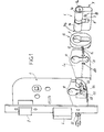
- the reference numeral 2 designates so general the case of a lock built into the mortise of an opening and comprising a latch bolt 3 and a deadbolt 4, actuable by the paneton 5 of a safety block 6.
- the safety block shown is of the type European and is composed of a body 7 in two parts 7a, 7b connected by a trigger guard 8, each part of the body forming an envelope for a cylinder 9a, 9b actuated by a key.
- the safety block 6 is placed in the door after the lock case has been engaged in the mortise of this door.
- This implementation is carried out by transversal engagement in housings in the door and in the housing and having the shape of those shown at 10 in Figure 1.
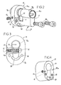
- part 7a of the security block which contains the cylinder 9a accessible from the outside by a key, is surrounded by a ring shield 12 whose internal housing 11 matches its external profile.
- the profile outside of this ring is oblong, as shown in FIGS. 1 and 2, circular or any other shape.
- This shield ring 12 is produced in a harder material than that constituting the body 7a, 7b and, for example alloy metallic, composite materials. It has a thickness which depends on the type of lock and which may be equal to, or less than, the length of the body part 7a on which it is mounted.
- the shield ring 12 For its connection with this body 7a, the shield ring 12 comprises a threaded bore 13 which, in the embodiment shown in FIG. 2, has a horizontal longitudinal axis arranged perpendicular to the axis longitudinal of the safety block 6 and substantially mid-thickness of the ring 12.
- This threaded bore 13 is intended to receive a grub screw 14 of which the anterior end, shouldered or not, is intended to penetrate a smooth housing 15, formed in part 7a of the body and below the corresponding cylinder 9a.
- the shield 12 is also crossed in its thickness by a blind bore 16, opening from the face posterior 12a of the shield and going from this face to the threaded bore 13.
- This bore 16 is intended to receive a burglar-resistant cylindrical pin 17, made of high resistance material.
- Figure 3 shows that when this pin 17 is placed in this housing 16 and penetrates substantially diametrically in the housing 13 for the grub screw 14, it prevents access the imprint 14a formed in this screw and makes it difficult to destruction by drilling.
- this pin is replaced by an insert, for example by a plate of resistant, metallic material, composite or otherwise.
- This insert is inserted into a housing similar to that 16 and whose cross section is identical to hers.
- the shield ring 12 is integral with a gutter 18 which projects from its rear face 12a and is intended to come below and in contact with trigger guard 8, connecting the two parts 7a and 7b of the body of the safety block.
- the cover 2a of the housing 2 includes a cutout 21 allowing the engagement of the gutter 18 in the housing.
- the shield ring 12 comprises at least one, and preferably two, threaded holes 19 intended to cooperate with a fixing screw 20.
- Each of these tapped holes is blind and opens from the rear side 12a of the shield.
- the two holes are arranged on either side of the plane vertical median of this shield and, in the embodiment shown, below body parts containing the cylinders.
- the safety block 6 - shield ring 12 assembly When the lock box 2 is placed in its mortise, the safety block 6 - shield ring 12 assembly is put in place, then is fixed by means of the two screws 20 which are engaged by the interior of the door. Each of them successively passes through a housing provided in the door, a housing 25 formed in the housing 2 and its cover 2a, and, finally housing in the door, before screwing into the threaded bore 19.
- a spacer 22 is arranged in this case, as shown in Figure 1.
- This spacer metallic or plastic, has passages 23 for the screws 20, but also a groove 24 for receiving the gutter 18 for strengthening the safety block.
- the shield ring can, depending on the thickness of the door, be supported directly on the housing, take support on the bottom of a housing made in the door, and, in this case, be flush with the front face of the door or overflow from the door.
- Figure 4 shows a shield that is longer than that shown in Figures 1 and 2 and which is intended, by its rear face 12a, to come to rest against the lock case, by its body to be partially embedded in the thickness of the door, and by its front part to form a projection by compared to the front of the door.
- the safety block fitted with such a shield ring is particularly resistant to violent break-in attempts, whatever the direction of these strikes, and, by its gutter, improves the resistance of the trigger guard 8, which is already improved by the elimination of the tapped hole the weakening in current safety blocks.
- the shield, the safety block, and the lock box form a more rigid and more resistant to extraction and sinking, which improves resistance to burglary.
- the grub screw 14 is screwed into a threaded bore 13 which opens from the rear face 12a of the ring 12 and whose longitudinal axis is oblique to the longitudinal axis from the body.
- the axis of the housing 15 receiving the screw 14 in the body is also oblique since it is coaxial with that of bore 13.
- This arrangement avoids providing a security insert 17 since access to screw 14 is hidden.
- the screw 14 is replaced by a pin which, cylindrical, conical or expandable, is forcibly engaged in bore 13, then not tapped, and in smooth bore 15.
- the longitudinal axes of these two bores are either radial, as shown in Figures 2 and 3, either oblique, as shown above.
- the bore in the shield 12 opens from the face posterior 12a thereof.
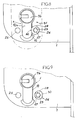
- FIG. 5 to 9 relates to a wedging device 26 for temporarily blocking the safety block 6, for example during a site where security is ensured by blocks of safety according to the invention, without shield 12 and without possibility of fixing by the traditional screw perpendicularly crossing the opening field.
- This device is composed of a cylindrical rod 27, integral with a head 28, also cylindrical but whose longitudinal axis is offset by an E value relative to the longitudinal axis of the rod, as shown in Figure 7.
- This head has an imprint 29 for a tool, and for example, an imprint hexagonal and, in its most eccentric part, a flat 30.
- the head 28 is cam-shaped, the part radially furthest from the axis of the rod 27 is disposed at the place of the flat 30.
- the temporary blocking of this safety block is ensured, on the inner part of the opening, by the engagement of the rod 27 in a bearing of the housing and by rotation of the device.
- the reception landing of the rod 27 is constituted by one of the housings 25 provided in the housing and the cover for the passage of the shield fixing screws 20.
- the bearing is formed by a housing different from those 25 of housing 2.
- Figure 9 shows that the rod 27 is first positioned so that its flat 30 is opposite the housing 10 for the passage of the safety block and either in a position called engagement, allowing to adjust the longitudinal position of the safety block 6 in the lock. Then, and like shown in Figure 8, the head 28 is rotated, for example in the direction of the arrow 31 in FIG. 8, so that its flat 30 comes to the contact of the body of the block 6. In this position, the head 28 presses the block of safety against the edges 10a of the housings10 and thus secures the block in the lock.
- the wedging device 26 is arranged entirely in the lock housing.
- the cylindrical rod 27 is freely mounted in rotation in bearings provided in the boot and the latter or its cover has an opening allowing access to the means 29 rotational drive in the head 28.
- This arrangement requires to make a hole in the door to access the drive means 29 of the head, but this hole can be easily concealed, on one side, by a plate of cleanliness, whether or not integral with the handle for actuating the latch bolt, and, on the other side, by the shield ring 12.
- the wedging device 26 allows, in a simple and fast way, to ensure the connection of a safety block with the housing of a lock to obtain a temporary fixing or permed.
- the lock which has just been described comprises a safety block with two cylinders, but it is obvious that the invention also applies to a block with an external cylinder and a button, or other actuating means inside.
Landscapes
- Auxiliary Devices For Machine Tools (AREA)
- Lock And Its Accessories (AREA)
- Superstructure Of Vehicle (AREA)
- Control Of Vending Devices And Auxiliary Devices For Vending Devices (AREA)
- Aiming, Guidance, Guns With A Light Source, Armor, Camouflage, And Targets (AREA)
- Burglar Alarm Systems (AREA)
- Mobile Radio Communication Systems (AREA)
Abstract
Description
Claims (10)
- Serrure avec bloc de sûreté anti comprenant un boítier (2) avec son mécanisme d'actionnement et au moins un logement transversal traversant (10) pour le corps (7, 7a, 7b) d'un bloc de sûreté (6), équipé d'au moins un cylindre (9a) actionnable de l'extérieur par une clé, serrure dans laquelle le corps (7) du bloc de sûreté est disposé dans un logement ménagé dans la porte et débouchant de la face extérieure de celle-ci, caractérisée en ce que la partie extérieure (7a) du corps du bloc de sûreté (6) est entouré, sur tout ou partie de sa longueur saillant du boítier de serrure (3), par un anneau bouclier (12), épousant le profil extérieur de ce corps (7a) et lié à lui par au moins un organe de liaison, tel que goupille ou vis sans tête (14), traversant cet anneau et pénétrant dans un logement (15) ménagé dans le corps (7a), au-dessous du rotor du cylindre, tandis que la fixation sur la porte de l'ensemble bloc de sûreté (6)-bouclier (12) est assurée par au moins une vis (20), engagée de l'intérieur de la porte et traversant la porte et le boítier (6) par des logements cylindriques, la dite vis se vissant dans un alésage taraudé (19), ménagé dans le bouclier (12) et débouchant de la face postérieure (12a) de celui-ci.
- Serrure avec bloc de sûreté anti effraction selon la revendication 1, caractérisée en ce que la vis sans tête (14) fixant le bouclier (12) sur le corps (7a) du bloc de sûreté (6) est disposé dans un alésage taraudé (13) ménagé transversalement dans l'anneau bouclier (12) et est protégée par un insert (17) en matériau à haute résistance pénétrant transversalement dans l'alésage taraudé (13) et disposé dans un logement (16) allant de la face arrière (12a) du bouclier (12) à cet alésage taraudé (13).
- Serrure avec bloc de sûreté anti effraction selon la revendication 1, caractérisée en ce que le bouclier (12) comporte, en saillie de sa face arrière (12a), une gouttière de renforcement (18) pénétrant dans le boítier de serrure (3) par une découpe (21) et venant sous et au contact du pontet (8).
- Serrure avec bloc de sûreté anti effraction selon la revendication 1, caractérisée en ce que chacune des vis de fixation (20) de l'ensemble bloc de sûreté (6)-bouclier (12) sur la porte traverse une entretoise de renfort (22) disposée dans le boítier de serrure (3) pour éviter la déformation des deux parois latérales de ce boítier.
- Serrure avec bloc de sûreté anti effraction selon la revendication 1, caractérisée en ce que l'anneau bouclier (12) est réalisé en matériau au moins aussi résistant que celui constituant le corps (7, 7a) du bloc de sûreté (6).
- Serrure avec bloc de sûreté anti effraction selon la revendication 1, caractérisée en ce que l'alésage taraudé (13) est ménagé dans l'anneau bouclier (12) de manière qu'il débouche de la face arrière (12a) de cet anneau et présente un axe longitudinal oblique, coaxial avec celui du logement (15) ménagé dans le corps.
- Serrure avec bloc de sûreté selon la revendication 1 caractérisée en ce que son boítier (6) comporte au moins un logement (25) qui, disposé parallèlement à la direction d'engagement du bloc de sûreté (6) dans ce boítier et près de l'ouverture (10) prévue pour le passage du bloc, forme palier pour la tige cylindrique (27) d'un dispositif de calage temporaire (26), dispositif dont la tête de blocage (28) est au moins munie d'une portée excentrée (30)apte, par rotation, à occuper soit une position de dégagement, dans laquelle elle est hors de la trajectoire d'engagement du bloc de sûreté (6) dans le boítier, soit une position de calage, dans laquelle elle est en appui contre le corps de ce bloc de sûreté (6) et assure son calage contre le boítier.
- Serrure de sûreté selon la revendication 7 caractérisée en ce que le logement formant palier pour le dispositif de calage temporaire (26) et l'un des logements (25) prévus dans le boítier (6) pour le passage des vis (20) de fixation du bouclier (12).
- Serrure de sûreté selon la revendication 7 caractérisée en ce que la tige (27) et la tête (28) sont disposés à l'intérieur du boítier (2) qui est équipé de paliers guidant la rotation de la tige (27) et d'une ouverture permettant d'accéder à la tête (28) pour l'entraíner en rotation.
- Serrure de sûreté selon la revendication 1 caractérisée en ce que l'organe de liaison du bouclier (12) avec la partie (7a) du corps (7) est constitué par une goupille emmanchée de force dans des alésages ménagés dans le bouclier (12) et dans cette partie (7a).
Applications Claiming Priority (4)
| Application Number | Priority Date | Filing Date | Title |
|---|---|---|---|
| FR0114489A FR2831911B1 (fr) | 2001-11-05 | 2001-11-05 | Bloc de surete anti effraction pour serrure |
| FR0114489 | 2001-11-05 | ||
| FR0204348A FR2838148B1 (fr) | 2002-04-08 | 2002-04-08 | Dispositif de calage du bloc de surete d'une serrure |
| FR0204348 | 2002-04-08 |
Publications (3)
| Publication Number | Publication Date |
|---|---|
| EP1308585A2 true EP1308585A2 (fr) | 2003-05-07 |
| EP1308585A3 EP1308585A3 (fr) | 2003-05-28 |
| EP1308585B1 EP1308585B1 (fr) | 2005-12-28 |
Family
ID=26213256
Family Applications (1)
| Application Number | Title | Priority Date | Filing Date |
|---|---|---|---|
| EP02356219A Expired - Lifetime EP1308585B1 (fr) | 2001-11-05 | 2002-11-04 | Serrure avec bloc de sûreté anti effraction |
Country Status (4)
| Country | Link |
|---|---|
| EP (1) | EP1308585B1 (fr) |
| AT (1) | ATE314544T1 (fr) |
| DE (1) | DE60208306T2 (fr) |
| ES (1) | ES2252415T3 (fr) |
Cited By (6)
| Publication number | Priority date | Publication date | Assignee | Title |
|---|---|---|---|---|
| GB2429748A (en) * | 2005-09-06 | 2007-03-07 | Cintor Ltd | Lock cylinder protection assembly |
| GB2456530A (en) * | 2008-01-16 | 2009-07-22 | Securistyle Ltd | Lock cylinder guard with reducible distance between opposing portions |
| EP1944438A3 (fr) * | 2007-01-13 | 2012-04-25 | Archibald Kenrick & Sons Ltd | Serrure cylindrique |
| GB2516430A (en) * | 2013-07-19 | 2015-01-28 | Grouphomesafe Ltd | Lock mechanism |
| CN104481208A (zh) * | 2014-12-05 | 2015-04-01 | 杨凯乐 | 一种有三重防盗功能的机械锁 |
| CN109505458A (zh) * | 2018-11-21 | 2019-03-22 | 中山市华博尔五金制品有限公司 | 一种门锁及其附件的安装方法 |
Families Citing this family (2)
| Publication number | Priority date | Publication date | Assignee | Title |
|---|---|---|---|---|
| ES2397153B1 (es) * | 2011-03-28 | 2013-10-15 | Talleres De Escoriaza, S.A. | Protector interior para cilindros de cerradura |
| ES2400555B1 (es) * | 2011-04-14 | 2013-11-25 | Talleres De Escoriaza, S.A. | Cilindro de cerradura mejorado |
Family Cites Families (5)
| Publication number | Priority date | Publication date | Assignee | Title |
|---|---|---|---|---|
| DE1553534C3 (de) * | 1966-05-20 | 1974-07-25 | Zeiss Ikon Ag, 7000 Stuttgart | Rosette für Zylinderschlösser |
| IL93619A0 (en) * | 1989-04-10 | 1990-12-23 | Yoav Weinberger | Improved covering mask for door-lock cylinder |
| DE9101242U1 (de) * | 1991-01-14 | 1992-05-14 | Melchert Beschläge GmbH & Co KG, 5628 Heiligenhaus | Beschlag für mit Einsteckschlössern und Profil-Schließzylindern ausgerüstete Türen |
| FR2708025B1 (fr) * | 1993-07-22 | 1995-09-15 | Vachette Sa | Dispositif de protection de barillet de serrure de porte. |
| DE29820558U1 (de) * | 1998-11-18 | 2000-03-30 | C. Ed. Schulte GmbH Zylinderschloßfabrik, 42551 Velbert | Auf einen Schließzylinder aufsteckbare Blende |
-
2002
- 2002-11-04 EP EP02356219A patent/EP1308585B1/fr not_active Expired - Lifetime
- 2002-11-04 ES ES02356219T patent/ES2252415T3/es not_active Expired - Lifetime
- 2002-11-04 DE DE60208306T patent/DE60208306T2/de not_active Expired - Lifetime
- 2002-11-04 AT AT02356219T patent/ATE314544T1/de not_active IP Right Cessation
Cited By (7)
| Publication number | Priority date | Publication date | Assignee | Title |
|---|---|---|---|---|
| GB2429748A (en) * | 2005-09-06 | 2007-03-07 | Cintor Ltd | Lock cylinder protection assembly |
| EP1944438A3 (fr) * | 2007-01-13 | 2012-04-25 | Archibald Kenrick & Sons Ltd | Serrure cylindrique |
| GB2456530A (en) * | 2008-01-16 | 2009-07-22 | Securistyle Ltd | Lock cylinder guard with reducible distance between opposing portions |
| GB2456530B (en) * | 2008-01-16 | 2013-03-06 | Securistyle Ltd | A guard |
| GB2516430A (en) * | 2013-07-19 | 2015-01-28 | Grouphomesafe Ltd | Lock mechanism |
| CN104481208A (zh) * | 2014-12-05 | 2015-04-01 | 杨凯乐 | 一种有三重防盗功能的机械锁 |
| CN109505458A (zh) * | 2018-11-21 | 2019-03-22 | 中山市华博尔五金制品有限公司 | 一种门锁及其附件的安装方法 |
Also Published As
| Publication number | Publication date |
|---|---|
| ATE314544T1 (de) | 2006-01-15 |
| EP1308585B1 (fr) | 2005-12-28 |
| ES2252415T3 (es) | 2006-05-16 |
| DE60208306T2 (de) | 2006-08-03 |
| DE60208306D1 (de) | 2006-02-02 |
| EP1308585A3 (fr) | 2003-05-28 |
Similar Documents
| Publication | Publication Date | Title |
|---|---|---|
| EP1308585B1 (fr) | Serrure avec bloc de sûreté anti effraction | |
| FR2708025A1 (fr) | Dispositif de protection de barillet de serrure de porte. | |
| EP2123851B1 (fr) | Mécanisme de serrure comportant un bouclier | |
| EP2825423B1 (fr) | Antivol à supercondamnation pour colonne de direction de véhicule automobile | |
| FR2831911A1 (fr) | Bloc de surete anti effraction pour serrure | |
| FR2564884A1 (fr) | Dispositif de securite pour serrure du genre en applique. | |
| EP0566483A1 (fr) | Dispositif anti-perçage pour serrure | |
| EP0520904A1 (fr) | Verrou à rotor débrayable | |
| EP1580356B1 (fr) | Dispositif de protection de barillet de serrure de porte | |
| EP0745745B1 (fr) | Dispositif de protection pour boítier servant au logement d'un mécanisme de commande d'une ferrure de verrouillage avec élément à clé | |
| FR2477617A1 (fr) | Rosette anti-effraction pour une serrure encastree | |
| EP0606196B1 (fr) | Dispositif de fermeture | |
| EP1688565B1 (fr) | Serrure à sécurité améliorée contre l'effraction | |
| FR2623231A1 (fr) | Dispositif de renforcement pour serrure a larder a bloc de surete et serrure pourvue d'un tel dispositif | |
| EP1580355B1 (fr) | Serrure de porte munie d'un coffre renforcé | |
| EP0252781A2 (fr) | Gâche de serrure, réglable, et procédé de fixation, la rendant ainsi fixée, particulièrement résistante aux effractions | |
| FR2934298A1 (fr) | Serrure a delateur | |
| FR2816975A1 (fr) | Dispositif de protection conte l'effraction de serrures a cylindres europeen | |
| EP3708747B1 (fr) | Serrure d'urgence adaptée pour être déverrouillée de l'intérieur | |
| EP1070812B1 (fr) | Serrure comprenant un dispositif de protection contre les tentatives d'effraction | |
| FR2763091A1 (fr) | Barillet de serrure pour serrure de securite | |
| FR2931506A1 (fr) | Mecanisme de serrure comportant un bouclier | |
| FR2705077A1 (fr) | Dispositif antivol pour motocycle. | |
| FR2599775A1 (fr) | Procede de fixation d'une gache de serrure et gache ainsi fixee resistant particulierement aux effractions | |
| FR2893063A1 (fr) | Serrure a pompe avec goupille et clef associee. |
Legal Events
| Date | Code | Title | Description |
|---|---|---|---|
| PUAI | Public reference made under article 153(3) epc to a published international application that has entered the european phase |
Free format text: ORIGINAL CODE: 0009012 |
|
| PUAL | Search report despatched |
Free format text: ORIGINAL CODE: 0009013 |
|
| AK | Designated contracting states |
Designated state(s): AT BE BG CH CY CZ DE DK EE ES FI FR GB GR IE IT LI LU MC NL PT SE SK TR |
|
| AX | Request for extension of the european patent |
Extension state: AL LT LV MK RO SI |
|
| AK | Designated contracting states |
Designated state(s): AT BE BG CH CY CZ DE DK EE ES FI FR GB GR IE IT LI LU MC NL PT SE SK TR |
|
| AX | Request for extension of the european patent |
Extension state: AL LT LV MK RO SI |
|
| 17P | Request for examination filed |
Effective date: 20030709 |
|
| AKX | Designation fees paid |
Designated state(s): AT BE BG CH CY CZ DE DK EE ES FI FR GB GR IE IT LI LU MC NL PT SE SK TR |
|
| 17Q | First examination report despatched |
Effective date: 20040803 |
|
| GRAP | Despatch of communication of intention to grant a patent |
Free format text: ORIGINAL CODE: EPIDOSNIGR1 |
|
| GRAS | Grant fee paid |
Free format text: ORIGINAL CODE: EPIDOSNIGR3 |
|
| GRAA | (expected) grant |
Free format text: ORIGINAL CODE: 0009210 |
|
| AK | Designated contracting states |
Kind code of ref document: B1 Designated state(s): AT BE BG CH CY CZ DE DK EE ES FI FR GB GR IE IT LI LU MC NL PT SE SK TR |
|
| PG25 | Lapsed in a contracting state [announced via postgrant information from national office to epo] |
Ref country code: IT Free format text: LAPSE BECAUSE OF FAILURE TO SUBMIT A TRANSLATION OF THE DESCRIPTION OR TO PAY THE FEE WITHIN THE PRESCRIBED TIME-LIMIT;WARNING: LAPSES OF ITALIAN PATENTS WITH EFFECTIVE DATE BEFORE 2007 MAY HAVE OCCURRED AT ANY TIME BEFORE 2007. THE CORRECT EFFECTIVE DATE MAY BE DIFFERENT FROM THE ONE RECORDED. Effective date: 20051228 Ref country code: SK Free format text: LAPSE BECAUSE OF FAILURE TO SUBMIT A TRANSLATION OF THE DESCRIPTION OR TO PAY THE FEE WITHIN THE PRESCRIBED TIME-LIMIT Effective date: 20051228 Ref country code: NL Free format text: LAPSE BECAUSE OF FAILURE TO SUBMIT A TRANSLATION OF THE DESCRIPTION OR TO PAY THE FEE WITHIN THE PRESCRIBED TIME-LIMIT Effective date: 20051228 Ref country code: CZ Free format text: LAPSE BECAUSE OF FAILURE TO SUBMIT A TRANSLATION OF THE DESCRIPTION OR TO PAY THE FEE WITHIN THE PRESCRIBED TIME-LIMIT Effective date: 20051228 Ref country code: FI Free format text: LAPSE BECAUSE OF FAILURE TO SUBMIT A TRANSLATION OF THE DESCRIPTION OR TO PAY THE FEE WITHIN THE PRESCRIBED TIME-LIMIT Effective date: 20051228 Ref country code: AT Free format text: LAPSE BECAUSE OF FAILURE TO SUBMIT A TRANSLATION OF THE DESCRIPTION OR TO PAY THE FEE WITHIN THE PRESCRIBED TIME-LIMIT Effective date: 20051228 |
|
| REG | Reference to a national code |
Ref country code: GB Ref legal event code: FG4D Free format text: NOT ENGLISH |
|
| REG | Reference to a national code |
Ref country code: CH Ref legal event code: EP |
|
| GBT | Gb: translation of ep patent filed (gb section 77(6)(a)/1977) |
Effective date: 20051229 |
|
| REG | Reference to a national code |
Ref country code: IE Ref legal event code: FG4D Free format text: LANGUAGE OF EP DOCUMENT: FRENCH |
|
| REF | Corresponds to: |
Ref document number: 60208306 Country of ref document: DE Date of ref document: 20060202 Kind code of ref document: P |
|
| PG25 | Lapsed in a contracting state [announced via postgrant information from national office to epo] |
Ref country code: DK Free format text: LAPSE BECAUSE OF FAILURE TO SUBMIT A TRANSLATION OF THE DESCRIPTION OR TO PAY THE FEE WITHIN THE PRESCRIBED TIME-LIMIT Effective date: 20060328 Ref country code: BG Free format text: LAPSE BECAUSE OF FAILURE TO SUBMIT A TRANSLATION OF THE DESCRIPTION OR TO PAY THE FEE WITHIN THE PRESCRIBED TIME-LIMIT Effective date: 20060328 Ref country code: GR Free format text: LAPSE BECAUSE OF FAILURE TO SUBMIT A TRANSLATION OF THE DESCRIPTION OR TO PAY THE FEE WITHIN THE PRESCRIBED TIME-LIMIT Effective date: 20060328 Ref country code: SE Free format text: LAPSE BECAUSE OF FAILURE TO SUBMIT A TRANSLATION OF THE DESCRIPTION OR TO PAY THE FEE WITHIN THE PRESCRIBED TIME-LIMIT Effective date: 20060328 |
|
| REG | Reference to a national code |
Ref country code: ES Ref legal event code: FG2A Ref document number: 2252415 Country of ref document: ES Kind code of ref document: T3 |
|
| NLV1 | Nl: lapsed or annulled due to failure to fulfill the requirements of art. 29p and 29m of the patents act | ||
| PLBE | No opposition filed within time limit |
Free format text: ORIGINAL CODE: 0009261 |
|
| STAA | Information on the status of an ep patent application or granted ep patent |
Free format text: STATUS: NO OPPOSITION FILED WITHIN TIME LIMIT |
|
| PG25 | Lapsed in a contracting state [announced via postgrant information from national office to epo] |
Ref country code: CH Free format text: LAPSE BECAUSE OF NON-PAYMENT OF DUE FEES Effective date: 20061130 Ref country code: MC Free format text: LAPSE BECAUSE OF NON-PAYMENT OF DUE FEES Effective date: 20061130 Ref country code: LI Free format text: LAPSE BECAUSE OF NON-PAYMENT OF DUE FEES Effective date: 20061130 |
|
| 26N | No opposition filed |
Effective date: 20060929 |
|
| REG | Reference to a national code |
Ref country code: CH Ref legal event code: PL |
|
| REG | Reference to a national code |
Ref country code: FR Ref legal event code: ST Effective date: 20070731 |
|
| PG25 | Lapsed in a contracting state [announced via postgrant information from national office to epo] |
Ref country code: FR Free format text: LAPSE BECAUSE OF NON-PAYMENT OF DUE FEES Effective date: 20061130 |
|
| PG25 | Lapsed in a contracting state [announced via postgrant information from national office to epo] |
Ref country code: EE Free format text: LAPSE BECAUSE OF FAILURE TO SUBMIT A TRANSLATION OF THE DESCRIPTION OR TO PAY THE FEE WITHIN THE PRESCRIBED TIME-LIMIT Effective date: 20051228 |
|
| PG25 | Lapsed in a contracting state [announced via postgrant information from national office to epo] |
Ref country code: TR Free format text: LAPSE BECAUSE OF FAILURE TO SUBMIT A TRANSLATION OF THE DESCRIPTION OR TO PAY THE FEE WITHIN THE PRESCRIBED TIME-LIMIT Effective date: 20051228 Ref country code: LU Free format text: LAPSE BECAUSE OF NON-PAYMENT OF DUE FEES Effective date: 20061104 |
|
| PG25 | Lapsed in a contracting state [announced via postgrant information from national office to epo] |
Ref country code: CY Free format text: LAPSE BECAUSE OF FAILURE TO SUBMIT A TRANSLATION OF THE DESCRIPTION OR TO PAY THE FEE WITHIN THE PRESCRIBED TIME-LIMIT Effective date: 20051228 |
|
| PGFP | Annual fee paid to national office [announced via postgrant information from national office to epo] |
Ref country code: GB Payment date: 20161006 Year of fee payment: 15 Ref country code: IE Payment date: 20161024 Year of fee payment: 15 Ref country code: DE Payment date: 20161018 Year of fee payment: 15 |
|
| PGFP | Annual fee paid to national office [announced via postgrant information from national office to epo] |
Ref country code: IT Payment date: 20161116 Year of fee payment: 15 Ref country code: PT Payment date: 20161018 Year of fee payment: 15 Ref country code: ES Payment date: 20161130 Year of fee payment: 15 Ref country code: BE Payment date: 20161125 Year of fee payment: 15 |
|
| REG | Reference to a national code |
Ref country code: DE Ref legal event code: R119 Ref document number: 60208306 Country of ref document: DE |
|
| GBPC | Gb: european patent ceased through non-payment of renewal fee |
Effective date: 20171104 |
|
| PG25 | Lapsed in a contracting state [announced via postgrant information from national office to epo] |
Ref country code: PT Free format text: LAPSE BECAUSE OF NON-PAYMENT OF DUE FEES Effective date: 20180504 |
|
| REG | Reference to a national code |
Ref country code: BE Ref legal event code: MM Effective date: 20171130 |
|
| REG | Reference to a national code |
Ref country code: IE Ref legal event code: MM4A |
|
| PG25 | Lapsed in a contracting state [announced via postgrant information from national office to epo] |
Ref country code: DE Free format text: LAPSE BECAUSE OF NON-PAYMENT OF DUE FEES Effective date: 20180602 Ref country code: IE Free format text: LAPSE BECAUSE OF NON-PAYMENT OF DUE FEES Effective date: 20171104 Ref country code: IT Free format text: LAPSE BECAUSE OF NON-PAYMENT OF DUE FEES Effective date: 20171104 |
|
| PG25 | Lapsed in a contracting state [announced via postgrant information from national office to epo] |
Ref country code: GB Free format text: LAPSE BECAUSE OF NON-PAYMENT OF DUE FEES Effective date: 20171104 Ref country code: BE Free format text: LAPSE BECAUSE OF NON-PAYMENT OF DUE FEES Effective date: 20171130 |
|
| REG | Reference to a national code |
Ref country code: ES Ref legal event code: FD2A Effective date: 20181221 |
|
| PG25 | Lapsed in a contracting state [announced via postgrant information from national office to epo] |
Ref country code: ES Free format text: LAPSE BECAUSE OF NON-PAYMENT OF DUE FEES Effective date: 20171105 |