EP1306953A1 - Durchführungsanordnung - Google Patents
Durchführungsanordnung Download PDFInfo
- Publication number
- EP1306953A1 EP1306953A1 EP02023810A EP02023810A EP1306953A1 EP 1306953 A1 EP1306953 A1 EP 1306953A1 EP 02023810 A EP02023810 A EP 02023810A EP 02023810 A EP02023810 A EP 02023810A EP 1306953 A1 EP1306953 A1 EP 1306953A1
- Authority
- EP
- European Patent Office
- Prior art keywords
- opening
- covers
- carrier
- support
- arrangement according
- Prior art date
- Legal status (The legal status is an assumption and is not a legal conclusion. Google has not performed a legal analysis and makes no representation as to the accuracy of the status listed.)
- Granted
Links
Images


Classifications
-
- H—ELECTRICITY
- H02—GENERATION; CONVERSION OR DISTRIBUTION OF ELECTRIC POWER
- H02G—INSTALLATION OF ELECTRIC CABLES OR LINES, OR OF COMBINED OPTICAL AND ELECTRIC CABLES OR LINES
- H02G3/00—Installations of electric cables or lines or protective tubing therefor in or on buildings, equivalent structures or vehicles
- H02G3/22—Installations of cables or lines through walls, floors or ceilings, e.g. into buildings
-
- B—PERFORMING OPERATIONS; TRANSPORTING
- B60—VEHICLES IN GENERAL
- B60R—VEHICLES, VEHICLE FITTINGS, OR VEHICLE PARTS, NOT OTHERWISE PROVIDED FOR
- B60R16/00—Electric or fluid circuits specially adapted for vehicles and not otherwise provided for; Arrangement of elements of electric or fluid circuits specially adapted for vehicles and not otherwise provided for
- B60R16/02—Electric or fluid circuits specially adapted for vehicles and not otherwise provided for; Arrangement of elements of electric or fluid circuits specially adapted for vehicles and not otherwise provided for electric constitutive elements
- B60R16/0207—Wire harnesses
- B60R16/0215—Protecting, fastening and routing means therefor
- B60R16/0222—Grommets
-
- H—ELECTRICITY
- H05—ELECTRIC TECHNIQUES NOT OTHERWISE PROVIDED FOR
- H05K—PRINTED CIRCUITS; CASINGS OR CONSTRUCTIONAL DETAILS OF ELECTRIC APPARATUS; MANUFACTURE OF ASSEMBLAGES OF ELECTRICAL COMPONENTS
- H05K1/00—Printed circuits
- H05K1/02—Details
- H05K1/11—Printed elements for providing electric connections to or between printed circuits
- H05K1/118—Printed elements for providing electric connections to or between printed circuits specially for flexible printed circuits, e.g. using folded portions
Definitions
- the invention relates to a sealed bushing arrangement for an electrical cable with a flat cross section, in particular a flexible one Flat cable (FFC) or a flexible printed circuit (FPC), and one Method for sealing such a bushing arrangement.
- FFC Flexible one Flat cable
- FPC flexible printed circuit
- Sealed cable bushings are particularly important, especially for electrical lines with a round cross-section or cable harnesses known. Sealed cable bushings are typically used there, where an electrical line from a dry area through the Opening in a partition into a wet area and Moisture must be prevented from the wet area penetrates through the cable entry into the dry area.
- Is for example, an electrical one located in the door of a motor vehicle Component, e.g. the drive of an electric window regulator, with a power supply located in the engine compartment of the motor vehicle, e.g. a car battery, must be used for this Power line cables from inside the vehicle body through the body panel outwards and accordingly from outside through the door panel into the inside of the door.
- a power supply located in the engine compartment of the motor vehicle, e.g. a car battery
- Known sealed grommets and methods for Sealing such bushing arrangements include, for example passing an electrical wire through one in a partition located opening and then pouring the opening with a liquid sealing material which, if necessary under the action of heat, hardens.
- the sealing material may go with it an insulation material of the electrical line a material connection one that cannot be solved later, which can be done in the case of later ones Repairs or when recycling the electrical components used may prove unfavorable.
- the invention has for its object a sealed bushing arrangement for an electrical cable with a flat cross section create that is as reliable as possible and special simple and especially after laying the electrical line can be made.
- a bushing arrangement has a carrier especially for separating a dry area from a wet area, for example a vehicle door panel or a vehicle body panel, in which an opening is provided, at least one electrical one Cable with a flat cross-section, in particular a flexible flat cable (FFC) or a flexible printed circuit (FPC), which is made possible by the Opening is that they have a Flat side in a support area adjacent to the opening on the Carrier rests, and a seal on at least two on opposite Carrier sides arranged covers that on both Carrier sides of the opening and the edge areas surrounding the opening of the wearer cover and in the support areas rest against the pipe in a sealing manner.
- FFC flexible flat cable
- FPC flexible printed circuit
- the invention proves to be particularly advantageous for electrical lines with a flat cross-section, for simple sealing solutions in Area of executions are not known. It will be more beneficial Way the flat sides of the line on edge areas of the Carrier exploited by covering in these support areas the line can be created. For a sealing fit against the Covers on the line are particularly exploited that the flat wire does not apply.
- the implementation arrangement according to the invention can in particular a dry area separated from the wet area by the support protect against the ingress of moisture from the wet area, by adding moisture to a carrier side facing the wet area over a gap between the line and the support area in the Opening comes through the cover on the other side of the carrier held in the opening and penetrating into the dry area is prevented.
- a reliable sealing effect is consequently achieved.
- the bushing arrangement according to the invention is open particularly easy to manufacture. Only two are required Covers that are so on opposite sides of the carrier be attached so that they surround the opening and the opening Cover the edge areas of the carrier in a sealing manner and on the electrical Apply a sealing seal to the line.
- the covers are preferably such trained that they are in the critical contact areas to the electrical Huddle the cable in such a way that at no point in the support areas a space between the carrier and cover or between Cable and cover is available, through which e.g. Moisture or Dust could enter.
- the implementation arrangement according to the invention is therefore particularly suitable for electrical cables with a flat Cross-section, as this is a sealing concern of the covers on the electrical line or the carrier in a transition area guaranteed between line and carrier in a simple manner can be.
- the seal of the bushing arrangement according to the invention also retrospectively, i.e. after laying the install electrical wiring.
- the electrical System or in particular an entire cable harness, e.g. an FPC wiring harness, of a motor vehicle completely relocated and only in the frame in a final assembly step, the seal is inserted subsequently, by inventing the covers on both sides of each Carrier, e.g. of a door panel.
- the covers can be removed and replaced Seal of the bushing arrangement according to the invention in a simple manner Renew wise.
- the individual can also be recycled easily separate components of the bushing assembly.
- the electrical line is stepped in the area of the opening Show course. Because of this training, the electrical runs Line in the case of a carrier side parallel at least in the region of the opening having carrier offset in parallel through the opening, whereby with its one flat side in a support area and with its other flat side in the other, on the opposite side of the support contact area located on the carrier.
- This course of the electrical line ensures that a support area of one side of the support on the other side of the support no support area, but a sealed edge area opposite, in which the cover lies directly on the carrier, so that one side of the carrier between the line and the support area into the opening penetrated moisture always through a on the other side of the carrier Directly fitting cover on penetration into a dry area is hindered.
- Bushing arrangement include a flexible cover Sheet material and in particular a film or fabric material. by virtue of its flexibility nestles in the edge areas particularly well on the surface of the carrier and the electrical Line on, so that a reliably sealing covering of the opening and all adjacent edge areas of the carrier also in the area the electrical line is guaranteed.
- the covers are preferably glued on and in particular self-adhesive educated. Such covers are particularly easy and without additional adhesives or other aids on the carrier Attach.
- the covers limited void between the covers at least partially filled by a sealing material surrounding the electrical line.
- This sealing material represents a barrier to external influences should not pass through the carrier opening.
- the adhesive works equally as Adhesive and as a sealing material, creating an additional sealing material can be dispensed with.
- the sealing material is advantageously in a pre-assembly state already attached to at least one of the covers. This makes it easier the manufacture of the seal, since the sealing material and the covers Prepare separately and therefore independently of the wearer to let.
- the sealing material is preferably deformable. This can Sealing material particularly well the contours of the electrical line and adjust the opening, which further increases the sealing effect of the sealing material elevated.
- the opening preferably has a greater width than the line.
- the covers touch each other in the side of the electrical Leading areas of the opening.
- they are Covers connected here and preferably glued.
- the electrical line is preferably at least in regions and especially in a central area of the opening with both covers at the same time in touch.
- the electrical line is special connected to the covers, preferably glued.
- Another object of the invention is a method for sealing a Bushing for at least one electrical cable with a flat cross section, especially a flexible flat cable (FFC) or a flexible one printed circuit (FPC) through an opening of a particular for Separation of a dry area from a wet area.
- Carrier for example a vehicle door panel or a vehicle body panel, is performed, in which the line through the opening is carried out on both sides of the carrier with a flat side in a support area adjacent to the opening on the carrier abuts, and the opening is sealed on both sides by covers, by placing a cover in the opening on both sides of the support and sealing edge areas surrounding the opening of the carrier Covering way is fixed to the carrier, the covers in the support areas are each sealed to the line.
- a through the covers limited cavity with sealing material a through the covers limited cavity with sealing material.
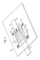
- a carrier 10 is shown, for example a vehicle body panel or a vehicle door panel that has a dry area from a wet area, for example the interior of a motor vehicle from the outside environment.
- a carrier 10 is one in this Example rectangular opening 12 is provided through which an electrical Line 14 is carried out.
- the electrical line 14 has a flat Cross section on.
- it can be a flexible flat cable (FFC) or a flexible printed circuit (FPC).
- a cover 16 is on each Carrier 10 attached to the opening 12 and an opening 12 surrounding edge region 18 of the carrier 10 covers.
- the covers 16 are formed from a flexible adhesive tape and are so over the opening 12 and the edge regions 18 of the carrier 10 are glued to them rest sealingly on the electrical line 14 and on the carrier 10. Undermining of the covers 16 by moisture due to Capillary forces are reliably prevented by the covers 16 especially in transition areas 20 between line 14 and carrier 10 sealingly to the electrical line 14 and to the carrier 10 nestle.
- the electrical line 14 stepped through the opening 12.
- the sections located outside the opening 12 22, 24 offset at least in regions parallel to one another, the electrical line 14 in a first adjoining the opening 12 Support area 26 with its upper flat side 28 and in one second bearing area 30 adjacent to the opening 12 with its lower flat side 32 abuts the carrier 10.
- the step-like course of the electrical line 14 ensures that that a support area 26 of the one carrier side on the other support side just not a support area, but an edge area 18 opposite, in which the cover 16 directly on the carrier 10 abuts so that on one side of the support between line 14 and support 10 penetrated moisture always by one on the other side of the carrier directly adjacent cover 16 at a crossing of the opening 12 and penetration into a dry area is prevented.
- the covers or the adhesive tape strips 16 are advantageously already provided with the sealing material 34 in a pre-assembly state and then in a covering the opening 12 and the edge regions 18 Glued on the carrier 10.
- the covers 16 can also be made of a two- or multi-component injection molding material be made that preformed in this way is that it seals on the respective carrier side to the electrical Line 14 and hugs the surface of the carrier 10. Also injection molded parts of this type, before they are glued to the carrier 10, with an additional sealing material 34 and / or a thickly applied Adhesive should be provided, the one between the injection molded parts existing cavity at least partially fills the electrical line 14 surrounds sealing.
- a carrier 10 is, for example, a Vehicle body or a vehicle door panel, with a right-angled Opening 12 shown through which an electrical line 14 with a flat Cross section, for example a flexible flat cable (FFC) or a flexible printed circuit (FPC), is passed in stages, one upper flat side 28 of the electrical line 14 in a first contact area 26 and a lower flat side 32 of the electrical line 14 in a second contact area 30 rests on the carrier 10.
- FFC flexible flat cable
- FPC flexible printed circuit
- the adhesive tapes are pressed into the opening 12 in such a way that they are located to the side of the electrical line 14 Touch areas 36 and are glued together.
- FIGS. 7 and 8 are the position of the section lines A-A and B-B of those in FIGS. 7 and 8 shown sectional views.
- FIG. 7 shows the section A-A in the longitudinal direction of the electrical line 14. It is shown how in the areas of the opening 12 in which the electrical Line 14 emerges from the opening 12, in each case one of the covers 16 is applied to the electrical line 14, while the respective another cover 16 rests in the edge region 18 of the carrier 10 and in the opening 12 is pressed in and in the direction of the line 14.
- the support area 38 delimiting the opening 12 is rectangular is the course of the electrical line 14 and the covers 16, however, is curved, arise through the electrical line 14, the Carrier area 38 and the cover 16 limited cavities 40, the Size in particular of flexibility, flexibility and / or lubricity the covers 16 and, if applicable, the thickness of an applied one Adhesive or any additional sealing material depends.
- Both covers 16 are in a central region 42 of the opening 12 the electrical line 14 glued.
- Moisture could e.g. from one side of the support at the support area 30 between line 14 and carrier 10 into the cavity 40 arrive.
- the moisture is prevented from leaving the cavity 40 and e.g. along line 14 to the other support area 26 and there between the line 14 and the carrier 10 through to the other Carrier side can reach.
- Fig. 8 shows the section B-B transverse to the longitudinal axis of the electrical line 14.
- the adhesive tapes 16 are in the edge regions 18 with the carrier 10 glued, pressed into the opening and into the side next to the Electric line 14 located areas 36 glued together.
- in the Center region 42 of the opening 12 are both covers 16 with the respective flat sides 28, 32 of the electrical line 14 glued.
- the electrical line 14 By gluing the electrical line 14 to the covers 16, the electrical line 14 is also in position with respect to the Carrier 10 fixed. In this way, a movement of electrical Line 14 practically excluded relative to the carrier 10.
- the covers 16 directly with the carrier 10 and the line 14 are connected and in particular glued Prevents moisture from entering, causing capillary effects e.g. can be prevented by thickly applied adhesive. Possibly at the support areas 26, 30 between line 14 and carrier 10 penetrating moisture is through the intimate connections the covers 16 with the line 14 on the one hand and the covers 16 prevented each other from doing the other To reach the carrier side.
- the covers 16 thus ensure that the support areas are sealed 26, 30 opposite the other side of the support, i.e. if necessary to the Support areas 26, 30 between line 14 and carrier 10 therethrough penetrating moisture cannot pass through the opening 12.
Landscapes
- Engineering & Computer Science (AREA)
- Architecture (AREA)
- Civil Engineering (AREA)
- Structural Engineering (AREA)
- Mechanical Engineering (AREA)
- Insertion, Bundling And Securing Of Wires For Electric Apparatuses (AREA)
- Installation Of Indoor Wiring (AREA)
Abstract
Description
- Fig. 1
- eine erste Variante einer erfindungsgemäßen Durchführungsanordnung;
- Fig. 2
- einen Querschnitt durch die Durchführungsanordnung in Fig. 1 entlang der Längsachse der elektrischen Leitung;
- Fig. 3
- einen Querschnitt der Durchführungsanordnung in Fig. 1 quer zur Längsrichtung der elektrischen Leitung;
- Fig. 4
- eine erfindungsgemäße Abdeckung mit vormontiertem Dichtmaterial;
- Fig. 5
- eine zweite Variante einer erfindungsgemäßen Durchführungsanordnung;
- Fig. 6
- eine Draufsicht auf die Durchführungsanordnung in Fig. 5;
- Fig. 7
- einen Querschnitt durch die Durchführungsanordnung in Fig. 5 entlang der Längsachse der elektrischen Leitung; und
- Fig. 8
- einen Querschnitt durch die Durchführungsanordnung in Fig. 5 quer zur Längsrichtung der elektrischen Leitung.
- 10
- Träger
- 12
- Öffnung
- 14
- elektrische Leitung
- 16
- Abdeckung
- 18
- Randbereich
- 20
- Übergangsbereich
- 22
- Leitungsabschnitt
- 24
- Leitungsabschnitt
- 26
- Auflagebereich
- 28
- obere Flachseite
- 30
- Auflagebereich
- 32
- untere Flachseite
- 34
- Dichtmaterial
- 36
- seitlicher Bereich
- 38
- Trägerbereich
- 40
- Hohlraum
- 42
- Mittenbereich
- 44
- Trägerbereich
- 46
- Hohlraum
- 48
- Hohlraum
Claims (14)
- Durchführungsanordnung mit
einem Träger (10) insbesondere zur Trennung eines Trockenbereiches von einem Nassbereich, beispielsweise einem Fahrzeugtürblech oder einem Fahrzeugkarosserieblech, in dem eine Öffnung (12) vorgesehen ist,
zumindest einer elektrischen Leitung (14) mit flachem Querschnitt, insbesondere einem flexiblen Flachkabel (FFC) oder einer flexiblen gedruckten Schaltung (FPC), die derart durch die Öffnung (12) geführt ist, dass sie auf beiden Trägerseiten jeweils mit einer Flachseite (28, 32) in einem an die Öffnung (12) angrenzenden Auflagebereich (26, 30) an dem Träger (10) anliegt, und
einer Dichtung, die zumindest zwei auf gegenüber liegenden Trägerseiten angeordnete Abdeckungen (16) aufweist, die auf beiden Trägerseiten jeweils die Öffnung (12) und die Öffnung (12) umgebende Randbereiche (18) des Trägers (10) abdichtend überdecken und in den Auflagebereichen (26, 30) jeweils abdichtend an der Leitung (14) anliegen. - Durchführungsanordnung nach Anspruch 1,
dadurch gekennzeichnet, dass die elektrische Leitung (14) im Bereich der Öffnung (12) einen stufenförmigen Verlauf aufweist. - Durchführungsanordnung nach Anspruch 1 oder 2,
dadurch gekennzeichnet, dass die Abdeckungen (16) ein flexibles Flächenmaterial und insbesondere ein Folien- oder Gewebematerial aufweisen. - Durchführungsanordnung nach einem der vorherigen Ansprüche,
dadurch gekennzeichnet, dass die Abdeckungen (16) aufgeklebt und insbesondere selbstklebend ausgebildet sind. - Durchführungsanordnung nach einem der vorherigen Ansprüche,
dadurch gekennzeichnet, dass die Abdeckungen (16) jeweils in Form eines Klebebands vorgesehen sind. - Durchführungsanordnung nach einem der vorherigen Ansprüche,
dadurch gekennzeichnet, dass ein von den Abdeckungen (16) begrenzter Hohlraum zwischen den Abdeckungen (16) zumindest teilweise durch ein die elektrische Leitung (14) umgebendes Dichtmaterial (34) ausgefüllt ist. - Durchführungsanordnung nach Anspruch 6,
dadurch gekennzeichnet, dass das Dichtmaterial (34) in einem Vormontagezustand bereits an zumindest einer der Abdeckungen (16) angebracht ist. - Durchführungsanordnung nach Anspruch 6 oder 7,
dadurch gekennzeichnet, dass das Dichtmaterial (34) verformbar ist. - Durchführungsanordnung nach einem der vorherigen Ansprüche,
dadurch gekennzeichnet, dass die Abdeckungen (16) in den seitlich der elektrischen Leitung (14) gelegenen Bereichen (36) der Öffnung (12) einander berühren und insbesondere miteinander verbunden, bevorzugt verklebt sind. - Durchführungsanordnung nach einem der vorherigen Ansprüche,
dadurch gekennzeichnet, dass die elektrische Leitung (14) zumindest bereichsweise und insbesondere in einem Mittenbereich (42) der Öffnung (12) mit beiden Abdeckungen (16) gleichzeitig in Berührung steht und insbesondere verbunden, bevorzugt verklebt ist. - Verfahren zum Abdichten einer Durchführung für zumindest eine elektrische Leitung (14) mit flachem Querschnitt, insbesondere ein flexibles Flachkabel (FFC) oder eine flexible gedruckte Schaltung (FPC), die durch eine Öffnung (12) eines insbesondere zur Trennung eines Trockenbereiches von einem Nassbereich vorgesehenen Trägers (10), beispielsweise eines Fahrzeugtürblechs oder eines Fahrzeugkarosserieblechs, geführt wird, bei dem
die Leitung (14) derart durch die Öffnung (12) geführt wird, dass sie auf beiden Trägerseiten jeweils mit einer Flachseite (28, 32) in einem an die Öffnung (12) angrenzenden Auflagebereich (26, 30) an dem Träger (10) anliegt, und
die Öffnung (12) beidseitig durch Abdeckungen (16) abgedichtet wird, indem auf beiden Trägerseiten jeweils eine Abdeckung (16) die Öffnung (12) und die Öffnung (12) umgebende Randbereiche (18) des Trägers (10) abdichtend überdeckend an dem Träger (10) fixiert wird, wobei die Abdeckungen (16) in den Auflagebereichen (26, 30) jeweils abdichtend an die Leitung (14) angelegt werden. - Verfahren nach Anspruch 11,
dadurch gekennzeichnet, dass ein durch die Abdeckungen (16) begrenzter Hohlraum mit Dichtmaterial (34) versehen wird. - Verfahren nach Anspruch 11 oder 12,
dadurch gekennzeichnet, dass die Abdeckungen (16) in seitlich der elektrischen Leitung (14) gelegenen Bereichen (36) der Öffnung (12) miteinander in Verbindung gebracht und insbesondere miteinander verklebt werden. - Verfahren nach einem der Ansprüche 11 bis 13,
dadurch gekennzeichnet, dass eine Durchführungsanordnung nach einem der Ansprüche 1 bis 10 verwendet wird.
Applications Claiming Priority (2)
| Application Number | Priority Date | Filing Date | Title |
|---|---|---|---|
| DE10152568 | 2001-10-24 | ||
| DE2001152568 DE10152568A1 (de) | 2001-10-24 | 2001-10-24 | Durchführungsanordnung |
Publications (2)
| Publication Number | Publication Date |
|---|---|
| EP1306953A1 true EP1306953A1 (de) | 2003-05-02 |
| EP1306953B1 EP1306953B1 (de) | 2009-04-08 |
Family
ID=7703623
Family Applications (1)
| Application Number | Title | Priority Date | Filing Date |
|---|---|---|---|
| EP20020023810 Expired - Lifetime EP1306953B1 (de) | 2001-10-24 | 2002-10-23 | Durchführungsanordnung |
Country Status (2)
| Country | Link |
|---|---|
| EP (1) | EP1306953B1 (de) |
| DE (2) | DE10152568A1 (de) |
Cited By (1)
| Publication number | Priority date | Publication date | Assignee | Title |
|---|---|---|---|---|
| EP2560258A3 (de) * | 2011-08-17 | 2014-10-29 | Johnson Electric S.A. | Flüssigkeitsdichte Kabeldurchführung für Flachkabel |
Citations (2)
| Publication number | Priority date | Publication date | Assignee | Title |
|---|---|---|---|---|
| JPH089538A (ja) * | 1994-06-16 | 1996-01-12 | Furukawa Electric Co Ltd:The | 配線接続具 |
| US6064003A (en) * | 1998-04-16 | 2000-05-16 | Lear Automotive Dearborn, Inc | Grommet and connector seal for use with flat flexible cable |
-
2001
- 2001-10-24 DE DE2001152568 patent/DE10152568A1/de not_active Withdrawn
-
2002
- 2002-10-23 DE DE50213427T patent/DE50213427D1/de not_active Expired - Lifetime
- 2002-10-23 EP EP20020023810 patent/EP1306953B1/de not_active Expired - Lifetime
Patent Citations (2)
| Publication number | Priority date | Publication date | Assignee | Title |
|---|---|---|---|---|
| JPH089538A (ja) * | 1994-06-16 | 1996-01-12 | Furukawa Electric Co Ltd:The | 配線接続具 |
| US6064003A (en) * | 1998-04-16 | 2000-05-16 | Lear Automotive Dearborn, Inc | Grommet and connector seal for use with flat flexible cable |
Non-Patent Citations (1)
| Title |
|---|
| PATENT ABSTRACTS OF JAPAN vol. 1996, no. 05 31 May 1996 (1996-05-31) * |
Cited By (1)
| Publication number | Priority date | Publication date | Assignee | Title |
|---|---|---|---|---|
| EP2560258A3 (de) * | 2011-08-17 | 2014-10-29 | Johnson Electric S.A. | Flüssigkeitsdichte Kabeldurchführung für Flachkabel |
Also Published As
| Publication number | Publication date |
|---|---|
| DE50213427D1 (de) | 2009-05-20 |
| DE10152568A1 (de) | 2003-05-08 |
| EP1306953B1 (de) | 2009-04-08 |
Similar Documents
| Publication | Publication Date | Title |
|---|---|---|
| DE112008003375T5 (de) | Wasserabdichtverfahren für einen Draht und Draht, welcher ein wasserdichtes Teil aufweist, welches durch das Wasserabdichtverfahren gebildet ist | |
| DE9004669U1 (de) | Verschlußanordnung für elektrische Verbindungen | |
| DE2608921A1 (de) | Abschirmstreifen fuer elektromagnetische stoerungen | |
| DE3532119A1 (de) | Elektrisch beheizbare autoglasscheibe | |
| DE102016103439B4 (de) | Kontaktstelle eines Flachleiters | |
| WO2003028114A2 (de) | Photovoltaik-isolieverglasung | |
| EP0895449A2 (de) | Elektrisch leitfähige Dichtung und Verfahren zu deren Herstellung | |
| DE69530806T2 (de) | Abdichtung für eine elektrische Verbindung einer Glasscheibe | |
| DE69423054T3 (de) | Glasscheibe mit Anschlusselement | |
| DE19732223A9 (de) | Funktionsintegrationsmodul mit einem Aggregateträger für elektrische Verbraucher, insbesondere Türaggregateträger für Kraftfahrzeugtüren | |
| EP1306953B1 (de) | Durchführungsanordnung | |
| DE102008058287B4 (de) | Elektronisches Modul mit einem Dichtelement und Verfahren zum Herstellen des Moduls | |
| EP3566271B1 (de) | Schaltschranktür für ein schaltschrankgehäuse | |
| DE19915151A1 (de) | Türmodulträger mit einem metallischen Grundkörper zum Verschließen einer Öffnung in einer Fahrzeugtür | |
| WO2002002362A1 (de) | Kabeldurchführung zwischen nass- und trockenraum in einer kraftfahrzeugtür | |
| EP1212813A1 (de) | Kabelverbindung zwischen flachbandkabel und rundbandkabel bzw. rundkabel und verfahren zu deren herstellung | |
| DE69304527T2 (de) | Kabeldurchführung mit erdung | |
| DE4037119C2 (de) | ||
| EP3859112B1 (de) | Elastisch nachgiebiges hohlprofil mit einer in einer kammer des hohlprofils fest integrierten elektrisch arbeitenden schaltleiste | |
| DE102024205945B3 (de) | Gehäusehälfte für ein Gehäuse und Gehäuse für eine elektrische Komponente | |
| DE10142835C1 (de) | Kraftfahrzeug-Baugruppe | |
| DE19734505A1 (de) | Verfahren zum Einbauen eines Kabelbaumes | |
| DE102017104893A1 (de) | Optoelektronikmodul | |
| DE102004018997B4 (de) | Elektronisches Gerät sowie Verfahren zur Herstellung eines derartigen elektronischen Geräts | |
| WO2017085193A1 (de) | Rahmen für ein fahrzeugdach |
Legal Events
| Date | Code | Title | Description |
|---|---|---|---|
| PUAI | Public reference made under article 153(3) epc to a published international application that has entered the european phase |
Free format text: ORIGINAL CODE: 0009012 |
|
| AK | Designated contracting states |
Designated state(s): AT BE BG CH CY CZ DE DK EE ES FI FR GB GR IE IT LI LU MC NL PT SE SK TR |
|
| AX | Request for extension of the european patent |
Extension state: AL LT LV MK RO SI |
|
| AKX | Designation fees paid | ||
| 17P | Request for examination filed |
Effective date: 20030528 |
|
| RBV | Designated contracting states (corrected) |
Designated state(s): DE FR IT |
|
| REG | Reference to a national code |
Ref country code: DE Ref legal event code: 8566 |
|
| 17Q | First examination report despatched |
Effective date: 20071213 |
|
| GRAP | Despatch of communication of intention to grant a patent |
Free format text: ORIGINAL CODE: EPIDOSNIGR1 |
|
| GRAS | Grant fee paid |
Free format text: ORIGINAL CODE: EPIDOSNIGR3 |
|
| GRAA | (expected) grant |
Free format text: ORIGINAL CODE: 0009210 |
|
| AK | Designated contracting states |
Kind code of ref document: B1 Designated state(s): DE FR IT |
|
| REF | Corresponds to: |
Ref document number: 50213427 Country of ref document: DE Date of ref document: 20090520 Kind code of ref document: P |
|
| PLBE | No opposition filed within time limit |
Free format text: ORIGINAL CODE: 0009261 |
|
| STAA | Information on the status of an ep patent application or granted ep patent |
Free format text: STATUS: NO OPPOSITION FILED WITHIN TIME LIMIT |
|
| 26N | No opposition filed |
Effective date: 20100111 |
|
| PGFP | Annual fee paid to national office [announced via postgrant information from national office to epo] |
Ref country code: DE Payment date: 20101020 Year of fee payment: 9 |
|
| PGFP | Annual fee paid to national office [announced via postgrant information from national office to epo] |
Ref country code: IT Payment date: 20101023 Year of fee payment: 9 |
|
| PGFP | Annual fee paid to national office [announced via postgrant information from national office to epo] |
Ref country code: FR Payment date: 20111103 Year of fee payment: 10 |
|
| REG | Reference to a national code |
Ref country code: FR Ref legal event code: ST Effective date: 20130628 |
|
| PG25 | Lapsed in a contracting state [announced via postgrant information from national office to epo] |
Ref country code: DE Free format text: LAPSE BECAUSE OF NON-PAYMENT OF DUE FEES Effective date: 20130501 |
|
| REG | Reference to a national code |
Ref country code: DE Ref legal event code: R119 Ref document number: 50213427 Country of ref document: DE Effective date: 20130501 |
|
| PG25 | Lapsed in a contracting state [announced via postgrant information from national office to epo] |
Ref country code: FR Free format text: LAPSE BECAUSE OF NON-PAYMENT OF DUE FEES Effective date: 20121031 Ref country code: IT Free format text: LAPSE BECAUSE OF NON-PAYMENT OF DUE FEES Effective date: 20121023 |