EP1306939A2 - Sertisseur - Google Patents
Sertisseur Download PDFInfo
- Publication number
- EP1306939A2 EP1306939A2 EP02023732A EP02023732A EP1306939A2 EP 1306939 A2 EP1306939 A2 EP 1306939A2 EP 02023732 A EP02023732 A EP 02023732A EP 02023732 A EP02023732 A EP 02023732A EP 1306939 A2 EP1306939 A2 EP 1306939A2
- Authority
- EP
- European Patent Office
- Prior art keywords
- pressure
- crimping
- unit
- display
- crimping operation
- Prior art date
- Legal status (The legal status is an assumption and is not a legal conclusion. Google has not performed a legal analysis and makes no representation as to the accuracy of the status listed.)
- Withdrawn
Links
Images


Classifications
-
- H—ELECTRICITY
- H01—ELECTRIC ELEMENTS
- H01R—ELECTRICALLY-CONDUCTIVE CONNECTIONS; STRUCTURAL ASSOCIATIONS OF A PLURALITY OF MUTUALLY-INSULATED ELECTRICAL CONNECTING ELEMENTS; COUPLING DEVICES; CURRENT COLLECTORS
- H01R43/00—Apparatus or processes specially adapted for manufacturing, assembling, maintaining, or repairing of line connectors or current collectors or for joining electric conductors
- H01R43/04—Apparatus or processes specially adapted for manufacturing, assembling, maintaining, or repairing of line connectors or current collectors or for joining electric conductors for forming connections by deformation, e.g. crimping tool
- H01R43/048—Crimping apparatus or processes
- H01R43/0486—Crimping apparatus or processes with force measuring means
-
- H—ELECTRICITY
- H01—ELECTRIC ELEMENTS
- H01R—ELECTRICALLY-CONDUCTIVE CONNECTIONS; STRUCTURAL ASSOCIATIONS OF A PLURALITY OF MUTUALLY-INSULATED ELECTRICAL CONNECTING ELEMENTS; COUPLING DEVICES; CURRENT COLLECTORS
- H01R43/00—Apparatus or processes specially adapted for manufacturing, assembling, maintaining, or repairing of line connectors or current collectors or for joining electric conductors
- H01R43/04—Apparatus or processes specially adapted for manufacturing, assembling, maintaining, or repairing of line connectors or current collectors or for joining electric conductors for forming connections by deformation, e.g. crimping tool
- H01R43/042—Hand tools for crimping
- H01R43/0427—Hand tools for crimping fluid actuated hand crimping tools
-
- H—ELECTRICITY
- H01—ELECTRIC ELEMENTS
- H01R—ELECTRICALLY-CONDUCTIVE CONNECTIONS; STRUCTURAL ASSOCIATIONS OF A PLURALITY OF MUTUALLY-INSULATED ELECTRICAL CONNECTING ELEMENTS; COUPLING DEVICES; CURRENT COLLECTORS
- H01R43/00—Apparatus or processes specially adapted for manufacturing, assembling, maintaining, or repairing of line connectors or current collectors or for joining electric conductors
- H01R43/04—Apparatus or processes specially adapted for manufacturing, assembling, maintaining, or repairing of line connectors or current collectors or for joining electric conductors for forming connections by deformation, e.g. crimping tool
- H01R43/042—Hand tools for crimping
- H01R43/0428—Power-driven hand crimping tools
Definitions
- the present invention relates to a crimping tool which is used to crimp a crimping terminal.
- a crimping tool which is operated by hand or by electricity. Also, such crimping tool is used not only to apply pressure directly to a crimping terminal using a gear mechanism or a link mechanism but also to apply pressure through oil pressure.
- This electrically-operated oil-pressure crimping tool is of a type that, using a piston 2 which can be moved forwardly from a main body 1, applies pressure to a crimping terminal set on a tool head portion 3. Specifically, a DC motor disposed in the interior of the main body is rotated to thereby drive an oil-pressure pump through a planetary gear reduction mechanism, the oil-pressure pump feeds oil within an oil tank to an oil-pressure cylinder, so that the piston 2 can be moved forwardly from the main body 1.
- the above-mentioned problems are similarly found not only in the above-mentioned electrically-operated oil-pressure crimping tool but also in a crimping tool which can be operated by hand or by other kinds of driving power. That is, the problems are not limited to the oil-pressure crimping tool.
- the present invention aims at eliminating the drawbacks found in the conventional crimping tool. Accordingly, it is an object of the invention to provide a crimping tool which not only can display pressure given in a crimping operation or the number of times of execution of crimping operations, whereby it is possible not only to judge easily whether any poor crimping has occurred in a crimping operation or not but also to judge whether the pressure applied in the crimping operation has been normal or not, thereby being able to confirm positively the occurrence of poor crimping in the crimping operation.
- a crimping tool having a crimping operation information detect unit for detecting information concerning a crimping operation; a pressure judge unit for judging, in accordance with the information detected by the crimping operation information detect unit, whether the pressure is normal or abnormal; and, a notifying unit for notifying the judge result.
- a crimping tool having a crimping operation information detect unit for detecting information concerning a crimping operation; a display unit for displaying quantity information; and, a display control unit for allowing the display unit to display the quantity information in accordance with information detected by the crimping operation information detect unit.
- a crimping tool according to the invention is not limited to a crimping tool which can obtain the pressure thereof from the driving power of an electric motor but it may be a crimping tool which can obtain the pressure thereof by hand. Also, in a crimping tool according to the invention, oil pressure may be used or may not in order to obtain the pressure thereof.
- a crimping tool having a crimping operation information detect unit for detecting information concerning a crimping operation; a pressure judge unit for judging, in accordance with the information detected by the crimping operation information detect unit, whether the pressure is normal or abnormal; and, a notifying unit for notifying the judge result.
- a crimping tool according to the invention is not limited to a crimping tool which can obtain pressure from the driving power of an electric motor but it may be a crimping tool which can obtain pressure by hand. Also, in a crimping tool according to the invention, oil pressure may be used or may not in order to obtain the pressure thereof.
- a pressure sensor for detecting pressure or an operation detector for detecting the execution of a crimping operation there can be used a pressure sensor for detecting pressure or an operation detector for detecting the execution of a crimping operation.
- a pressure sensor for detecting the drive current of the electric motor used when executing the crimping operation.
- a DC motor provides an almost linear relationship between the drive current and output torque thereof; and, in most of other types of electric motors as well, the drive current and output torque thereof are mutually related. Therefore, in case where the maximum value of the drive current is known, the maximum pressure applied to the crimping operation can be obtained by analogy and, using the pressure judge unit, it can be judged whether the crimping operation has been executed normally or not. Also, in case where the current detector is used, there is eliminated the need to dispose a pressure sensor in the oil-pressure cylinder and, therefore, simply by modifying an electric circuit, the invention can be enforced easily.
- an electrically-operated crimping tool is not limited to a tool which directly applies pressure to the crimping terminal using the drive power of an electric motor, but it may also be a tool which applies pressure to the crimping terminal through oil pressure using the drive power of an electric motor.
- an electrically-operated oil-pressure crimping tool which uses an electric motor to drive an oil-pressure cylinder to thereby generate pressure to be applied in a crimping operation, not only is simple in structure but also, even in case where various unit according to the invention are incorporated therein, can be made compact. That is, preferably, there may be used such electrically-operated oil-pressure crimping tool.
- the electric motor preferably, there may be used a DC motor.
- a DC motor there may be used a DC motor.
- the reason for this is as follows: that is, since the DC motor has an almost linear relationship between the drive current and output torque thereof, circuits are easy to design and thus the DC motor is easy to control, and also a battery can be used as the power supply of the DC motor, which not only allows an operator to carry the crimping tool with him or her but also permits the crimping tool to be used regardless of an operation place.
- These crimping operation information detect unit may be used independently or may be used in combination; for example, a pressure sensor and an operation detector may be combined together, or, a current detector and an operation detector may be combined together.
- the display control unit may be structured such that it allows the maximum pressure value detected by the present pressure sensor during one crimping operation to be displayed.
- the display control unit may be structured such that it allows the maximum current value detected by the present current detector during one crimping operation to be displayed.
- the display control unit may be structured such that it not only counts the number of times of execution of crimping operations detected by the present detector but also allows the count result to be displayed.
- the display unit which is used to display the quantity information, displays a numerical value or a quantity through a display state including three or more conditions.
- the display of numerical values is executed, for example, by displaying single figures or more according to the decimal display system; and, such numerical value display has an advantage that the pressure value of oil pressure and the number of times of execution of operations can be clearly shown to the operator.
- a display device for displaying figures according to the decimal display system in this manner for example, there can be used an LED (Light Emitting Diode) display device or a liquid crystal display device which uses a 7-segment display or a dot matrix display.
- the display of quantities is executed by displaying the quantities of the numerical value information through graphical representation; and, such quantity display has an advantage that the pressure value of oil pressure and the number of times of execution of operations can be shown to the operator in an intuitively-easy-to-understand manner.
- the operator when the numerical values such as the pressure values of the oil pressure are displayed, the operator must have knowledge about the range of the normal pressure values.
- the pressure values are displayed by the quantity display system, the operator can judge by intuition from proper indexes whether the pressure values are normal or not.
- a display device for displaying the quantities through graphical representation for example, there can be used an LED display device or a liquid crystal display device which, by enlarging or reducing lighted or transmitted ranges which are continuous with one another, displays the quantities in bar graphs or in circle graphs, using a 7-segment display or a dot matrix display.
- the bar graphs or circle graphs can also be displayed stagelessly in an analog manner, for example, by rotating a cylinder or a disk by a proper angle.
- the quantities can also be displayed through varying shades or colors.
- the display unit for displaying the quantities includes a printer which prints the quantities on paper to thereby put them on record.
- the pressure to be applied in a crimping operation is detected by the pressure sensor and the maximum value of the pressure is displayed by the display unit. This allows the operator to judge easily whether a sufficient value of pressure has been applied by the crimping operation or not.
- the drive current of a DC motor in a crimping operation is detected by the current detector and the maximum value of the drive current is displayed by the displayunit. Since the DC motor has an almost linear relationship between the drive current and output torque thereof, in case where the maximum value of the drive current is known, the maximum oil pressure applied in the crimping operation can be found, which makes it possible to judge easily whether the crimping has been executed with a sufficient value of pressure or not. Also, because there is eliminated the need for provision of a sensor in the interior of an oil pressure cylinder, only by modifying an electric circuit, the invention can be enforced simply.
- the display control unit can also be structured such that, instead of allowing the maximum value of the drive current to be displayed as it is, it allows the display unit to display the maximum value of the drive current in the form of a numerical value converted into oil pressure.
- the execution of individual crimping operations is detected and the count results of the number of times of detection is displayed by the display unit. Thanks to this, it is possible for the operator to confirm whether a poor condition can occur in the crimping operation due to the life of the crimping tool itself or the life of the head portion of the tool; and also, it is possible for the operator to know whether the crimping tool itself or the parts of the tool must be replaced or not.
- a crimping tool having crimping operating information detect unit for detecting information concerning a crimping operation; pressure judge unit for judging in accordance with the information detected by the crimping operation information detect unit whether the pressure is normal or abnormal; and, notifying unit for notifying the judgment result.
- a user who uses the present crimping tool, is allowed to know easily whether the crimping operation has been executed normally or not. Further, in case where it is found that the crimping operation has been executed abnormally, the user is allowed to immediately stop the operation and take appropriate measures.
- the crimping tool of the invention comprises not only the above-mentioned crimping operation information detect unit, pressure judge unit and notifying unit but also display unit for displaying quantity information and display control unit for allowing the display unit to display the quantity information. Therefore, a user, who uses the present crimping tool, is allowed to judge easily by referring to the thus displayed quantity information whether the crimping operation has been executed normally or not.
- these crimping operation information detect unit may be used independently or may be used in combination; for example, a pressure sensor and an operation detector may be combined together, or, a current detector and an operation detector may be combined together.
- the pressure sensor can also be used in combination with the current detector.
- the value detected by the pressure sensor can be compared with the value detected by the current detector and thus the detected values can be corrected, which makes it possible to judge the pressure with more accuracy.
- the crimping tool is not limited to a tool of an electrically-operated type that the pressure thereof can be obtained through the drive force of an electric motor.
- the crimping tool may also be a tool of a type that the pressure thereof can be obtained by hand.
- the pressure may be obtained through oil pressure or not through the oil pressure.
- the crimping operation information detect unit for detecting information concerning pressure applied in a crimping operation there can be used a pressure sensor for detecting the pressure in the crimping operation; and, in the case of an electrically-operated crimping tool, there can be used a current detector for detecting the drive current of an electric motor.
- the pressure judge unit is unit which, in accordance with a pressure value detected by the pressure sensor or a drive current value detected by the current detector, judges whether the pressure is normal or abnormal.
- the pressure judge unit may be composed of a comparison circuit capable of setting a given voltage value or a given current value serving as a standard for judgment, and a record circuit for recording the normal or abnormal state of the pressure.
- the notifying unit is unit which notifies a user, who uses the present crimping tool, of the judgment results through lights or sounds . For example, in case where the pressure is found abnormal, an LED may by turned on or a buzzer may be sounded. Due to this, the user using the present crimping tool is allowed to know immediately whether the crimping operation is good or not. By the way, the notifying unit has only to notify at least one of the normal and abnormal judgment results.
- the crimping tool of the invention since the pressure detected by the crimping operation information detect unit is judged by the pressure judge unit, it is possible to know whether the crimping operation has been carried out normallyornot. Such judgment result can be notified immediately to the user using the present crimping tool; and, at the same time, in the case of an electrically-operated oil-pressure crimping tool, there may be disposed unit which, when the crimping operation is found abnormal, shuts off the current and oil pressure system, so that the operation can be forcibly stopped immediately.
- the judgment results of the pressure may be put on record or, in case where there is disposed unit for transferring the record to a management department, thereby being able to add such recording function to the crimping tool. Thanks to this, the parts of the crimping tool, which has a possibility of being poorly crimped, can be collected before the present crimping tool is delivered.
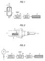
- Figs. 1 to 5 show an embodiment of a crimping tool according to the invention.
- Fig. 1 is a block diagram of a circuit which detects the oil pressure of an oil-pressure cylinder and displays the thus detected oil pressure on an LED display device
- Fig. 2 is a plan view of an electrically-operated oil-pressure crimping tool, showing the LED display device disposed in a main body thereof
- Fig. 3 is a block diagram of a circuit which detects the drive current of a DC motor and displays the detected drive current on an LED display device
- Fig. 4 is a block diagram of a circuit using an LED display device which can display bar graphs
- Fig. 5 is a block diagram of a circuit which counts the number of times of execution of crimping operations and displays the count results on an LED display device.
- Figs. 6 to 8 also show the above embodiment of a crimping tool according to the invention.
- Fig. 6 is a block diagram of a circuit which, when the oil pressure of the oil-pressure cylinder in the crimping operation increases up to a sufficiently high value, turns on an LED
- Fig. 7 is a block diagram of a circuit which, when the drive current of the DC motor increases up to a sufficiently high value, sounds a buzzer
- Fig. 8 is a block diagram of a circuit which, when the oil pressure of the oil-pressure cylinder in the crimping operation increases up to a sufficiently high value, turns on an LED and also displays the maximum value of the present oil pressure.
- an electrically-operated oil-pressure crimping tool which is similar to the conventional crimping tool shown in Fig. 9.
- an electrically-operated oil-pressure crimping tool according to the present embodiment as shown in Fig. 2, on the upper surface of a main body 1 thereof, there are disposed an LED display device 8 and a display button 9.
- the LED display device 8 is a display device which displays six-figure numbers through the 7-segment display of an LED.
- the display button 9 is a switch which switches the on/off of the display by the LED display device 8.
- a pressure sensor 11 is mounted on an oil-pressure cylinder 10 which is disposed in the interior of the main body 1.
- the pressure sensor 11 is a sensor which detects the oil pressure in the interior of the oil-pressure cylinder 10 for pressing against a piston 2.
- the pressure value of the oil pressure detected by the pressure sensor 11 is transmitted to a peak hold circuit 12.
- This peak hold circuit 12 is a circuit which holds the maximum value of the oil pressure detected by the pressure sensor 11 and, by resetting a value held in the start time of a crimping operation, at the time of the end of the present crimping operation, is able to continue to output the maximum value of the oil pressure obtained during the present crimping operation.
- the maximum value of the oil pressure output by the peak hold circuit 12 is transmitted to a display driver 13.
- This display driver 13 is a circuit which allows the LED display device 8 to display the maximum value of the oil pressure output by the peak hold circuit 12 in the form of figures according to the decimal display system.
- the detect value to be output by the pressure sensor 11 is an analog signal which is normally composed of a voltage value.
- the peak hold circuit 12, using an operational amplifier and a condenser can be configured as an analog circuit which outputs the maximum value of the voltage value.
- the display driver 13 is able to quantize the present maximum value and control the 7-segment displays of the respective figures numbers of the LED display device 8 to thereby display them as figures according to the decimal display system.
- the peak hold circuit 12 and display driver 13 are respectively composed of a microcomputer mounted on the back surface of a substrate on which the LED display device 8 is disposed. Therefore, the detect value of the oil pressure output by the pressure sensor 11 is input to the analog input terminal of this microcomputer, where it is A-D converted and is thereby processed as a digital signal. Also, the peak hold circuit and display driver 13 are respectively composed of the program of the microcomputer.
- the initial value of the oil pressure is set in a given rewritable storage area; and, in each sampling, the detect value of the oil pressure input from the pressure sensor 11 is compared with the initial value set in the given storage area and, only when the detect value is larger than the initial value, the initial value is replaced with the present detect value, while such replacement processings are repeated, thereby being able to hold the maximum value of the oil pressure obtained during the present crimping operation after completion of the present crimping operation.
- the display driver 13 for example, in the case of a dynamic display, in each display scan, the value set in the given storage area is read out and is converted into data for a 7-segment display, and on/off signals are sequentially output to the respective segments of the respective figures of the LED display device 8, thereby being able to display figures according to the decimal display system.
- the maximum value of the oil pressure in the present crimping operation can be displayed by the LED display device 8. Therefore, by confirming whether the present maximum value exceeds a given value and thus the oil pressure has been sufficient for the crimping or not, the operator is able to judge whether the crimping operation has been performed normally or not.
- the pressure sensor 11 in the case of the crimping operation information detect unit, description has been given of a structure using the pressure sensor 11 disposed in the interior of the oil-pressure cylinder 10.
- this is not limitative but, for example, provided that it is capable of detecting the pressure of the piston 2, the pressure sensor 11 may also be disposed at any position on the oil pressure circuit, or the pressure sensor 11 may be disposed at a position where it is able to detect directly the pressure of the piston 2.
- the drive current of a DC motor 14 disposed in the interior of the main body 1 may be detected by a current detector 15 and the present detect value may be used instead of the detect value of the pressure sensor 11. Since the DC motor 14 provides an almost linear relationship between the drive current and output torque thereof, by detecting the drive current, it is possible to know the output torque of the DC motor 14, that is, the oil pressure to be applied to the oil-pressure cylinder 10 by an oil-pressure pump. In the case of the structure shown in Fig. 3, the maximum value of the drive current is held by the peak hold circuit 12 and is displayed on the LED display device 8 through the display driver 13.
- the numeric value representing the maximum value of the drive current can also be displayed after it is converted into a numeric value representing the maximum value of the oil pressure.
- the current detector 15 is used in this manner, not only there can be eliminated the need for use of the pressure sensor 11 which is expensive and troublesome to handle, but also there can be avoided the need for time and labor for sealing and fixing the pressure sensor 11 to the interior of the oil-pressure cylinder 10. That is, simply by modifying the electric circuit, the invention can be enforced at a low cost.
- LED display device 8 for displaying numeric values.
- LED display device 16 which displays quantities.
- twelve narrow and long LED display segments are arranged in a row and, as the value to be displayed increases, these twelve display segments are turned on sequentially in the order starting from the left side shown in Fig. 4, that is, the number of the turned-on or lighted display segments is increased in this order to thereby display the values in a bar-graph manner.
- LED display device 16 can provide the following advantage: that is, even when the actual value of the oil pressure or drive current necessary in the crimping operation is not known, in case where the number of the turned-on display segments exceeds nine but any one of the remaining three display segments disposed on the right end side in Fig. 4 and differing in the light emitting colors is not turned on, the operator can understand by intuition that a sufficient value of oil pressure has not been obtained; that is, there can be obtained an advantage that it is easy for the operator to judge whether the crimping operation has been executed normally or not.
- the LED display device 16 for displaying quantities there can be used not only an LED display device which displays the quantities in such a bar-graph manner as illustrated in Fig. 4 but also an LED display device which displays the quantities in a circular-graph manner. Further, there can also be used a display device which can changes the light emitting colors or the light emitting intensities step by step or steplessly according to the values to be displayed.
- the display unit in the case of the display unit, description has been given of the structure using the LED display device 8 and the structure using the LED display device 16.
- any other display unit provided that it can display numeric values or quantities using a display manner including at least three states; for example, there can be used an LED display device 8 and an LED display device 16 each of a dot matrix system.
- the display unit is not limited to a display device using an LED but it is also possible to use a liquid crystal display device.
- the display unit may be linked with a printer; that is, whenever a crimping operation is executed, the operation is printed on paper to thereby display the execution of the operation, so that the crimping operations, which have been executed previously, can be put on record.
- the crimping operation detector 17 may be structured such that it need not always detect the execution of the individual crimping operations one by one with accuracy.
- the operation of the piston 2 may be detected by a microswitch; that is, in case where the piston 2 advances a given distance or more and then returns, it may be defined uniformly that one crimping operation is completed.
- the start and completion of the crimping operation may also be detected through the varying patterns of the oil pressure in the interior of the oil-pressure cylinder 10 or through the varying patterns of the drive current of the DC motor 14.
- the counter circuit 18 and display driver 13 may be respectively composed of a logical circuit, or, similarly to the above-mentioned embodiment, they may be composed of a microcomputer. In case where the number of times of execution of the crimping operations is counted and displayed in the above manner, it is possible to confirm not only the need for replacement of the parts of the electrically-operated oil-pressure crimping tool but also the life of the electrically-operated oil-pressure crimping tool itself in accordance with the thus displayed number of times.
- what is displayed by the display unit such as the LED display device 8 is not limited to the maximum pressure value and the number of times of execution of crimping operations that are mentioned above, but other pieces of information concerning the crimping operations can also be displayed by the display unit.
- the life of the electrically-operated oil-pressure crimping tool can be surmised more accurately while differences between the habits of operators, differences between the materials and shapes of crimping terminals are taken into consideration.
- the numeric information can be displayed.
- the information can also be displayed independently of the display button 9.
- display can be executed when the main switch of the electrically-operated oil-pressure crimping tool is put into operation, or such display can be executed only for a given period of time after completion of each crimping operation.
- Such display can be performed for a given period of time after the display button 9 is depressed.
- the maximum pressure may be previously detected and the number of times of execution of crimping operations may be previously counted using a microcomputer; and, these displays can be switched over to each other by pressing down the display button 9.
- numeric information concerning the maximum pressure value and the number of times of execution of crimping operations are displayed by the display unit such as the LED display device 8.
- the present numeric information not only can be displayed by the display unit such as the LED display device 8 but also can be automatically printed on paper by a printer each time the crimping operation is executed or can be printed while an operator is operating a printer.
- an LED may be blinked in red for display or alarm unit such as a buzzer may give an alarm.
- a pressure sensor 11 is mounted on an oil-pressure cylinder 10 which is disposed in the interior of a main body 1.
- This pressure sensor 11 is a sensor which is used to detect the oil pressure in the interior of the oil-pressure cylinder 10 for pressing against a piston 2.
- the pressure value of oil pressure detected by the pressure sensor 11 is transmitted to a comparison circuit 19.
- the output of the comparison circuit 19 is transmitted to a memory circuit 20, while the output of the memory circuit 20 is transmitted to an LED 21.
- the detect value of the oil pressure to be output from the pressure sensor 11 is an analog signal which normally includes a voltage value.
- the comparison circuit 19 can compare the voltage value of the oil pressure with a given voltage value V ref using an operational amplifier and also can output a binary signal indicating whether the voltage value of the oil pressure exceeds the given voltage value V ref or not.
- a reset signal is transmitted to a reset terminal RESET thereof to thereby previously prepare the memory circuit 20 so as to allow an abnormal signal to be output from an output terminal Q thereof as an initial value.
- the memory circuit 20 can switch the state of the flipflop circuit to thereby allow a normal signal to be output from the output terminal Q from that time on. That is, in case where the voltage value of the oil pressure from the start of the crimping operation to the end thereof never exceeds the given voltage value V ref , the memory circuit 20 continues to output an abnormal signal; and, on the other hand, in case where the voltage value of the oil pressure exceeds the given voltage value V ref at least once, the memory circuit 20 outputs a normal signal.
- the given voltage value V ref is a voltage value which is obtained when the minimum value for making the oil pressure value sufficiently high for a crimping operation is made to correspond to the detect value of the oil pressure of the pressure sensor 11.
- an LED 21 is a light emitting diode element which is disposed on the upper surface of the main body 1 and has a green color as the light emitting color thereof. In case where a normal signal is output from the memory circuit 20, the LED 21 is turned on, which makes it possible to notify an operator that the crimping operation is completed.
- the comparison circuit 19 and memory circuit 20 are respectively composed of a microcomputer mounted on a substrate which is disposed in the interior of the main body 1. Therefore, the detect value of the oil pressure output from the pressure sensor 11 is input to the analog input terminal of this microcomputer, where the detect value is A-D converted and is thereby processed as a digital signal. Also, the comparison circuit 19 and memory circuit 20 are respectively composed of the programs of the microcomputers. That is, the comparison circuit 19 is composed of a program which, in each sampling, compares the detect value of the oil pressure input therein through the analog input terminal with its associated one of the given voltage values V ref stored in the appropriate storage areas.
- the comparison circuit 19 executes no processing and, in case where the detect value of the oil pressure exceeds the given voltage values V ref , the comparison circuit 19 shifts its control to the program of the memory circuit 20.
- the memory circuit 20 is composed of a program which rewrites the data of a specific output port. This output port is set in a data output state which, in the start time of a crimping operation, shows an abnormal state as an initial value.
- the comparison circuit 19 judges that the detect value of the oil pressure exceeds the given voltage values V ref , the output port is rewritten to a data output state which shows a normal state by the memory circuit 20.
- the LED 21 is connected to the present output port and, when data showing the normal state is output, the LED 21 can be turned on.
- the operator is able to know from the turned-on LED 21 that the oil pressure during the present crimping operation has exceeded the given voltage value V ref at least once and thus there has been obtained a sufficient output for the present crimping.
- the LED 21 is structured such that it can be turned on only when the crimping operation is executed normally, there can be eliminated a fear that occurrence of poor crimping can be overlooked when the LED 21 is not turned on due to its breakdown.
- the pressure sensor 11 may be disposed at any position on the oil-pressure circuit, provided that it is able to detect the pressure of the piston 2; or, the pressure sensor 11 can also be disposed at such a position that permits direct detection of the pressure of the piston 2.
- the drive current of a DC motor 14 disposed in the interior of the main body 1 may be detected by a current detector 15 and the thus detected value may be used instead of the detect value of the pressure sensor 11. Since the DC motor 14 has an almost linear relationship between the drive current and output torque thereof, by detecting the drive current, it is possible to know the output torque of the DC motor 14, that is, the oil pressure that is applied to the oil-pressure cylinder 10 by an oil-pressure pump. Also, it is also possible to use any one of other electric motors than the DC motor 14, provided that it has a correlation between the drive current and output torque thereof. In the case of the structure shown in Fig.
- the value of the drive current is compared with a given voltage value V ref V by a comparison circuit 19 and the comparison result is transmitted through a memory circuit 20 to a buzzer 22.
- the drive current of the DC motor 14 is detected as a voltage value by the current detector 15; and, the given voltage value V ref V is a voltage value which can be obtained when the minimum pressure value necessary for the oil pressure to be sufficiently high pressure for a crimping operation is made to correspond to the detected voltage value of the current detector 15.
- Use of such current detector 15 not only can eliminate the need for use of the pressure sensor 11 which is expensive and troublesome to handle, but also can avoid the time and labor to seal and fix the pressure sensor 11 to the interior of the oil-pressure cylinder 10. That is, only by modifying the electric circuit, the invention can be enforced at low cost.
- the buzzer 22 is structured such that, when the memory circuit 20 outputs data showing a normal state, it gives out a sound to thereby notify the operator of the effect that a sufficiently large value of pressure has been obtained. However, such confirming sound may only be given for a short period of time and, therefore, preferably, after completion of the crimping operation, a reset signal may be transmitted immediately to the memory circuit 20 to stop the sound. Also, the buzzer 22 may also be structured such that, only when the memory circuit 20 is outputting data showing an abnormal state even after completion of the crimping operation, it can give out an alarm sound to thereby notify the operator of the effect that the pressing force of the crimping operation has been short.
- an LED 21 may also be blinked in red as an alarm light.
- the completion of the crimping operation can be detected by detecting, for example, the operation of the piston 2. That is, in case where the piston 2 is advanced and returned by a given distance or more, it can be considered uniformly that one crimping operation is completed. Also, the completion of the crimping operation can be detected through the varying pattern of the oil pressure within the oil-pressure cylinder 10 or through the varying pattern of the drive current of the DC motor 14.
- the maximum value of oil pressure detected by the pressure sensor 11 can be displayed by an LED display device 16 of a seven-segment display type.
- the detect value of the pressure sensor 11 is transmitted to a peak hold circuit 12, where the maximum value is detected.
- the peak hold circuit 12 is a circuit which holds the maximum value of the oil pressure detected by the pressure sensor 11.
- the peak hold circuit 12 for example, there can be used the analog circuit such as an operational amplifier or a condenser; and, the peak hold circuit 12 can also be composed of the program of a microcomputer.
- the maximum value of the oil pressure held by the peak hold circuit 12 is displayed as decimal figures through a display driver 13 by the LED display device 16.
- the operator is able to know more specific information. For example, even in case where a crimping operation is ended normally, when there has been output only the oil pressure that exceeds the necessary pressure only slightly, there can be surmised a high possibility that, in case where the crimping operation is repeated as it is, poor crimping can occur in the crimping operation.
- the LED display device 16 there is used the LED display device 16.
- not only the numeric values may be displayed on the display device but also quantities corresponding to these numeric values may be displayed using bar graphs.
- the comparison circuit 19 compares the maximum value of the oil pressure held by the peak hold circuit 12 with a given value to thereby check whether the former has exceeded the latter or not, and the comparison result the comparison circuit 19 is transmitted to the LED 21. That is, here, since the peak hold circuit 12 holds the maximum value of the oil pressure, there is eliminated the need for use of the memory circuit 20. Also, in case where it is necessary to obtain only the judgment result by comparison, the memory unit such as the memory circuit 20 and peak hold circuit 12 is not always necessary. And, what is detected by the pressure sensor 11 is not limited to the oil pressure of the oil-pressure cylinder 10 but the pressure of the piston 2 can be detected directly by the pressure sensor 11. Also, as shown in Fig. 7, the drive current of the DC motor 14 can be detected.
- the invention can also be applied similarly to other oil-pressure crimping tools which can be operated by other drive power than the electric power or by hand. Further, the invention can also be applied to a crimping tool which does not use-oil pressure.
- the crimping tool of the invention since information concerning a crimping operation such as the maximum pressure in the crimping operation and the number of times of execution of crimping operations is displayed as quantity information, it is possible to judge easily whether the crimping operation has been executed normally or not as well as whether the crimping tool needs maintenance or not.
- the crimping tool of the invention because it is possible to judge whether the pressure in the crimping operation has been equal to or more than a given value, the possibility of occurrence of poor crimping in the crimping operation can be grasped with accuracy. For example, in case where a normal level of pressure has not been obtained, when such judgment result is notified to an operator, the operator is able to immediately stop the present crimping operation and take appropriate measures. Also, in case where the present judgment result is recorded, the parts of the crimping tool, which hold the possibility of causing poor crimping, can be collected before the present crimping tool is delivered.
Landscapes
- Engineering & Computer Science (AREA)
- Manufacturing & Machinery (AREA)
- Manufacturing Of Electrical Connectors (AREA)
- Measuring Fluid Pressure (AREA)
Applications Claiming Priority (4)
| Application Number | Priority Date | Filing Date | Title |
|---|---|---|---|
| JP2001329300 | 2001-10-26 | ||
| JP2001329299A JP2003136421A (ja) | 2001-10-26 | 2001-10-26 | 圧着工具 |
| JP2001329300A JP2003136420A (ja) | 2001-10-26 | 2001-10-26 | 圧着工具 |
| JP2001329299 | 2001-10-26 |
Publications (2)
| Publication Number | Publication Date |
|---|---|
| EP1306939A2 true EP1306939A2 (fr) | 2003-05-02 |
| EP1306939A3 EP1306939A3 (fr) | 2004-01-28 |
Family
ID=26624137
Family Applications (1)
| Application Number | Title | Priority Date | Filing Date |
|---|---|---|---|
| EP02023732A Withdrawn EP1306939A3 (fr) | 2001-10-26 | 2002-10-23 | Sertisseur |
Country Status (6)
| Country | Link |
|---|---|
| US (1) | US20030079513A1 (fr) |
| EP (1) | EP1306939A3 (fr) |
| KR (1) | KR20030035944A (fr) |
| CN (1) | CN1413801A (fr) |
| SG (1) | SG102696A1 (fr) |
| TW (1) | TW592876B (fr) |
Cited By (5)
| Publication number | Priority date | Publication date | Assignee | Title |
|---|---|---|---|---|
| FR2899830A1 (fr) * | 2006-04-13 | 2007-10-19 | Sofragraf Soc Par Actions Simp | "appareil de pose d'agrafes deformables" |
| EP2722133A3 (fr) * | 2007-05-16 | 2014-09-17 | Gustav Klauke GmbH | Procédé de fonctionnement d'une presse manuelle à actionnement motorisé et presse manuelle |
| EP3299126A1 (fr) * | 2016-09-22 | 2018-03-28 | Airlane Technologies | Outil de sertissage sans matrice |
| DE102017128909A1 (de) * | 2017-09-27 | 2019-03-28 | Erko Spolka Z Ograniczona Odpowiedzialnoscia Spolka Komandytowa | Crimpenverfahren von Verbindern oder Kabelschuhen und Vorrichtung zur Durchführung des Verfahrens |
| EP4177574A1 (fr) * | 2021-11-09 | 2023-05-10 | Norelem SAS | Dispositif indicateur pour un outil de serrage comportant un capteur d'effort de serrage |
Families Citing this family (9)
| Publication number | Priority date | Publication date | Assignee | Title |
|---|---|---|---|---|
| JP2005144564A (ja) * | 2003-11-11 | 2005-06-09 | Matsushita Electric Works Ltd | 可搬式電動工具 |
| CN100372195C (zh) * | 2005-07-13 | 2008-02-27 | 南京埃斯顿数字技术有限公司 | 通用端子压着机压力监控系统 |
| US20130233043A1 (en) * | 2012-01-25 | 2013-09-12 | Daniels Manufacturing Corporation | Method and apparatus for establishing calibration cycles based on actual tool use for tooling and instruments requiring periodic calibration |
| JP6720133B2 (ja) * | 2014-07-07 | 2020-07-08 | センブレ エス.ピー.エー. | 流体力学圧縮工具の動作方法、及び、流体力学圧縮工具 |
| WO2016205404A1 (fr) * | 2015-06-15 | 2016-12-22 | Milwaukee Electric Tool Corporation | Outil de sertissage hydraulique |
| CN105204464A (zh) * | 2015-09-18 | 2015-12-30 | 深圳市志海和科技有限公司 | 一种线束压着品质在线管理系统和方法 |
| ITUB20161240A1 (it) * | 2016-03-02 | 2017-09-02 | Cembre Spa | Pompa idraulica per un utensile idrodinamico di compressione |
| EP3213881B1 (fr) | 2016-03-02 | 2022-01-26 | CEMBRE S.p.A. | Outil de coupe ou de compression hydrodynamique |
| CN109732541B (zh) * | 2019-01-23 | 2020-10-27 | 浙江大学 | 一种带有气压传感器和微控制器的电锤 |
Citations (10)
| Publication number | Priority date | Publication date | Assignee | Title |
|---|---|---|---|---|
| US4418562A (en) * | 1981-03-02 | 1983-12-06 | Japan Storage Battery Company Ltd. | Control device for a small press |
| EP0291329A2 (fr) * | 1987-05-13 | 1988-11-17 | The Furukawa Electric Co., Ltd. | Procédé pour détecter des défauts de sertissage d'une pièce de travail sertie et dispositif de sertissage d'une borne mettant en oeuvre celui-ci |
| EP0463530A2 (fr) * | 1990-06-27 | 1992-01-02 | Framatome Connectors Usa Inc. | Appareil et méthode pour commander le sertissage d'objets |
| US5477680A (en) * | 1994-09-13 | 1995-12-26 | Burndy Corporation | Motor driven hydraulic tool with variable displacement hydraulic pump |
| JPH0914211A (ja) * | 1995-06-30 | 1997-01-14 | Sanwa Tekki Corp | 油圧圧縮器 |
| JPH0927378A (ja) * | 1995-07-13 | 1997-01-28 | Yazaki Corp | 電線端子圧着不良検出装置 |
| US5657417A (en) * | 1995-05-02 | 1997-08-12 | Burndy Corporation | Control for battery powered tool |
| DE29806179U1 (de) * | 1998-04-03 | 1998-10-08 | Connectool Gmbh & Co | Crimpzange |
| US5901440A (en) * | 1995-06-12 | 1999-05-11 | Yazaki Corporation | Control method of terminal crimping device |
| DE19932961A1 (de) * | 1999-07-14 | 2001-01-18 | Connectool Gmbh & Co | Verfahren zum Aufrüsten einer Zange mit einer Wegmeßeinrichtung, Wegmeßeinrichtung und mit ihr aufgerüstete Zange |
Family Cites Families (6)
| Publication number | Priority date | Publication date | Assignee | Title |
|---|---|---|---|---|
| US4598740A (en) * | 1983-04-25 | 1986-07-08 | Frederick Sloan | Hand tool with visual display means |
| DE3842009C1 (fr) * | 1988-11-22 | 1990-03-22 | Kabelwerke Reinshagen Gmbh, 5600 Wuppertal, De | |
| US5152162A (en) * | 1990-06-27 | 1992-10-06 | Burndy Corporation | System and method for crimping articles |
| FR2707757B1 (fr) * | 1993-07-15 | 1995-08-25 | Snecma | Outil pour mesurer une force de serrage exercée par une tige mobile d'appareil de mesure de longueur. |
| DE9312808U1 (de) * | 1993-08-26 | 1993-10-28 | Novopress Gmbh | Meßgerät zur Erfassung der Einschubtiefe bei einer Rohrverbindung |
| JPH09330779A (ja) * | 1996-06-12 | 1997-12-22 | Yazaki Corp | 端子圧着装置の制御方法 |
-
2002
- 2002-10-17 SG SG200206349A patent/SG102696A1/en unknown
- 2002-10-23 EP EP02023732A patent/EP1306939A3/fr not_active Withdrawn
- 2002-10-23 TW TW091124502A patent/TW592876B/zh not_active IP Right Cessation
- 2002-10-25 KR KR1020020065377A patent/KR20030035944A/ko not_active Application Discontinuation
- 2002-10-25 US US10/280,063 patent/US20030079513A1/en not_active Abandoned
- 2002-10-25 CN CN02148086A patent/CN1413801A/zh active Pending
Patent Citations (10)
| Publication number | Priority date | Publication date | Assignee | Title |
|---|---|---|---|---|
| US4418562A (en) * | 1981-03-02 | 1983-12-06 | Japan Storage Battery Company Ltd. | Control device for a small press |
| EP0291329A2 (fr) * | 1987-05-13 | 1988-11-17 | The Furukawa Electric Co., Ltd. | Procédé pour détecter des défauts de sertissage d'une pièce de travail sertie et dispositif de sertissage d'une borne mettant en oeuvre celui-ci |
| EP0463530A2 (fr) * | 1990-06-27 | 1992-01-02 | Framatome Connectors Usa Inc. | Appareil et méthode pour commander le sertissage d'objets |
| US5477680A (en) * | 1994-09-13 | 1995-12-26 | Burndy Corporation | Motor driven hydraulic tool with variable displacement hydraulic pump |
| US5657417A (en) * | 1995-05-02 | 1997-08-12 | Burndy Corporation | Control for battery powered tool |
| US5901440A (en) * | 1995-06-12 | 1999-05-11 | Yazaki Corporation | Control method of terminal crimping device |
| JPH0914211A (ja) * | 1995-06-30 | 1997-01-14 | Sanwa Tekki Corp | 油圧圧縮器 |
| JPH0927378A (ja) * | 1995-07-13 | 1997-01-28 | Yazaki Corp | 電線端子圧着不良検出装置 |
| DE29806179U1 (de) * | 1998-04-03 | 1998-10-08 | Connectool Gmbh & Co | Crimpzange |
| DE19932961A1 (de) * | 1999-07-14 | 2001-01-18 | Connectool Gmbh & Co | Verfahren zum Aufrüsten einer Zange mit einer Wegmeßeinrichtung, Wegmeßeinrichtung und mit ihr aufgerüstete Zange |
Non-Patent Citations (2)
| Title |
|---|
| PATENT ABSTRACTS OF JAPAN vol. 1997, no. 05, 30 May 1997 (1997-05-30) -& JP 09 014211 A (SANWA TEKKI CORP), 14 January 1997 (1997-01-14) * |
| PATENT ABSTRACTS OF JAPAN vol. 1997, no. 05, 30 May 1997 (1997-05-30) -& JP 09 027378 A (YAZAKI CORP), 28 January 1997 (1997-01-28) * |
Cited By (7)
| Publication number | Priority date | Publication date | Assignee | Title |
|---|---|---|---|---|
| FR2899830A1 (fr) * | 2006-04-13 | 2007-10-19 | Sofragraf Soc Par Actions Simp | "appareil de pose d'agrafes deformables" |
| WO2007119018A1 (fr) * | 2006-04-13 | 2007-10-25 | Sofragraf | Appareil de pose d'agrafes deformables. |
| EP2722133A3 (fr) * | 2007-05-16 | 2014-09-17 | Gustav Klauke GmbH | Procédé de fonctionnement d'une presse manuelle à actionnement motorisé et presse manuelle |
| EP3299126A1 (fr) * | 2016-09-22 | 2018-03-28 | Airlane Technologies | Outil de sertissage sans matrice |
| DE102017128909A1 (de) * | 2017-09-27 | 2019-03-28 | Erko Spolka Z Ograniczona Odpowiedzialnoscia Spolka Komandytowa | Crimpenverfahren von Verbindern oder Kabelschuhen und Vorrichtung zur Durchführung des Verfahrens |
| EP4177574A1 (fr) * | 2021-11-09 | 2023-05-10 | Norelem SAS | Dispositif indicateur pour un outil de serrage comportant un capteur d'effort de serrage |
| FR3128992A1 (fr) * | 2021-11-09 | 2023-05-12 | Norelem Sas | Dispositif indicateur pour un outil de serrage comportant un capteur d’effort de serrage |
Also Published As
| Publication number | Publication date |
|---|---|
| KR20030035944A (ko) | 2003-05-09 |
| CN1413801A (zh) | 2003-04-30 |
| TW592876B (en) | 2004-06-21 |
| SG102696A1 (en) | 2004-03-26 |
| US20030079513A1 (en) | 2003-05-01 |
| EP1306939A3 (fr) | 2004-01-28 |
Similar Documents
| Publication | Publication Date | Title |
|---|---|---|
| EP1306939A2 (fr) | Sertisseur | |
| EP0589328B1 (fr) | Pompe-seringue avec affichage graphique des conditions d'erreur | |
| US8210275B2 (en) | Power tools | |
| US6212449B1 (en) | Diagnosing malfunctions in materials handling vehicles | |
| JP4116078B2 (ja) | 電気かみそりまたはそれと共働する装置及び情報を評価するための配置 | |
| US5801964A (en) | Electronic monitoring apparatus for cyclic machines | |
| CN210524947U (zh) | 电子扳手 | |
| EP1679031A1 (fr) | Tensiometre electronique | |
| US6717523B2 (en) | Photoelectric switch | |
| KR100647114B1 (ko) | 프로그래머블 논리 제어 시스템 | |
| US7013722B2 (en) | System and method for determining air pressure | |
| JPH1123330A (ja) | 自転車用表示装置 | |
| JP2008234634A (ja) | 光学的情報読取装置 | |
| US5432706A (en) | Multimeter having min/max time stamp | |
| US20030149911A1 (en) | Rapid self-error-check circuit of a computer power supply | |
| US4926353A (en) | Measuring apparatus for determining the degree of utilization of a machine | |
| US20080314209A1 (en) | Torque wrench with detection and display of torque | |
| JPS63147649A (ja) | インクジエツトプリンタ | |
| EP1171217B1 (fr) | Indicateur pour filtre | |
| JP2003136421A (ja) | 圧着工具 | |
| JP2019529873A (ja) | 状況表示が一体化された照明付き目盛盤 | |
| JP2003136420A (ja) | 圧着工具 | |
| CN109015506B (zh) | 一种数显扭力扳手及其操作方法 | |
| US4577285A (en) | Gage block management system | |
| JPH0117439Y2 (fr) |
Legal Events
| Date | Code | Title | Description |
|---|---|---|---|
| PUAI | Public reference made under article 153(3) epc to a published international application that has entered the european phase |
Free format text: ORIGINAL CODE: 0009012 |
|
| AK | Designated contracting states |
Designated state(s): AT BE BG CH CY CZ DE DK EE ES FI FR GB GR IE IT LI LU MC NL PT SE SK TR |
|
| AX | Request for extension of the european patent |
Extension state: AL LT LV MK RO SI |
|
| PUAL | Search report despatched |
Free format text: ORIGINAL CODE: 0009013 |
|
| AK | Designated contracting states |
Kind code of ref document: A3 Designated state(s): AT BE BG CH CY CZ DE DK EE ES FI FR GB GR IE IT LI LU MC NL PT SE SK TR |
|
| AX | Request for extension of the european patent |
Extension state: AL LT LV MK RO SI |
|
| 17P | Request for examination filed |
Effective date: 20040308 |
|
| 17Q | First examination report despatched |
Effective date: 20040422 |
|
| AKX | Designation fees paid |
Designated state(s): DE FR GB |
|
| STAA | Information on the status of an ep patent application or granted ep patent |
Free format text: STATUS: THE APPLICATION IS DEEMED TO BE WITHDRAWN |
|
| 18D | Application deemed to be withdrawn |
Effective date: 20081007 |
|
| REG | Reference to a national code |
Ref country code: HK Ref legal event code: WD Ref document number: 1051936 Country of ref document: HK |