EP1306718B1 - Wellenlängenumsetzer - Google Patents
Wellenlängenumsetzer Download PDFInfo
- Publication number
- EP1306718B1 EP1306718B1 EP00963066A EP00963066A EP1306718B1 EP 1306718 B1 EP1306718 B1 EP 1306718B1 EP 00963066 A EP00963066 A EP 00963066A EP 00963066 A EP00963066 A EP 00963066A EP 1306718 B1 EP1306718 B1 EP 1306718B1
- Authority
- EP
- European Patent Office
- Prior art keywords
- light
- phase
- signal
- modulation
- output
- Prior art date
- Legal status (The legal status is an assumption and is not a legal conclusion. Google has not performed a legal analysis and makes no representation as to the accuracy of the status listed.)
- Expired - Lifetime
Links
Images


Classifications
-
- G—PHYSICS
- G02—OPTICS
- G02F—OPTICAL DEVICES OR ARRANGEMENTS FOR THE CONTROL OF LIGHT BY MODIFICATION OF THE OPTICAL PROPERTIES OF THE MEDIA OF THE ELEMENTS INVOLVED THEREIN; NON-LINEAR OPTICS; FREQUENCY-CHANGING OF LIGHT; OPTICAL LOGIC ELEMENTS; OPTICAL ANALOGUE/DIGITAL CONVERTERS
- G02F1/00—Devices or arrangements for the control of the intensity, colour, phase, polarisation or direction of light arriving from an independent light source, e.g. switching, gating or modulating; Non-linear optics
- G02F1/35—Non-linear optics
- G02F1/353—Frequency conversion, i.e. wherein a light beam is generated with frequency components different from those of the incident light beams
- G02F1/3536—Four-wave interaction
-
- G—PHYSICS
- G02—OPTICS
- G02F—OPTICAL DEVICES OR ARRANGEMENTS FOR THE CONTROL OF LIGHT BY MODIFICATION OF THE OPTICAL PROPERTIES OF THE MEDIA OF THE ELEMENTS INVOLVED THEREIN; NON-LINEAR OPTICS; FREQUENCY-CHANGING OF LIGHT; OPTICAL LOGIC ELEMENTS; OPTICAL ANALOGUE/DIGITAL CONVERTERS
- G02F1/00—Devices or arrangements for the control of the intensity, colour, phase, polarisation or direction of light arriving from an independent light source, e.g. switching, gating or modulating; Non-linear optics
- G02F1/01—Devices or arrangements for the control of the intensity, colour, phase, polarisation or direction of light arriving from an independent light source, e.g. switching, gating or modulating; Non-linear optics for the control of the intensity, phase, polarisation or colour
- G02F1/21—Devices or arrangements for the control of the intensity, colour, phase, polarisation or direction of light arriving from an independent light source, e.g. switching, gating or modulating; Non-linear optics for the control of the intensity, phase, polarisation or colour by interference
- G02F1/211—Sagnac type
-
- G—PHYSICS
- G02—OPTICS
- G02F—OPTICAL DEVICES OR ARRANGEMENTS FOR THE CONTROL OF LIGHT BY MODIFICATION OF THE OPTICAL PROPERTIES OF THE MEDIA OF THE ELEMENTS INVOLVED THEREIN; NON-LINEAR OPTICS; FREQUENCY-CHANGING OF LIGHT; OPTICAL LOGIC ELEMENTS; OPTICAL ANALOGUE/DIGITAL CONVERTERS
- G02F2201/00—Constructional arrangements not provided for in groups G02F1/00 - G02F7/00
- G02F2201/02—Constructional arrangements not provided for in groups G02F1/00 - G02F7/00 fibre
-
- G—PHYSICS
- G02—OPTICS
- G02F—OPTICAL DEVICES OR ARRANGEMENTS FOR THE CONTROL OF LIGHT BY MODIFICATION OF THE OPTICAL PROPERTIES OF THE MEDIA OF THE ELEMENTS INVOLVED THEREIN; NON-LINEAR OPTICS; FREQUENCY-CHANGING OF LIGHT; OPTICAL LOGIC ELEMENTS; OPTICAL ANALOGUE/DIGITAL CONVERTERS
- G02F2203/00—Function characteristic
- G02F2203/06—Polarisation independent
Definitions
- the present invention is related to a wavelength conversion apparatus, and more specifically, to an optical fiber wavelength conversion apparatus having a high conversion efficiency.
- All optical type wavelength converters are very important devices used to construct advanced wavelength division multiplexing (WDM) networks with flexibility in the future.
- a specific attention has been paid to wavelength conversion operations using four-wave mixing (FWM) operations within optical fibers, since the wavelength conversion techniques can own very broad wavelength conversion bands, and also can convert multi-channel WDM signals in a batch-manner.
- the wavelength conversions using the four-wave mixing (FWM) operations within the optical fibers own very wide wavelength conversion bands and can convert wavelength division multiplexing signals for multiple channels in the batch mode.
- JP 08 095093 A discloses a wavelength conversion device using four light wave mixing.
- EP 0 862 078 A1 discloses an optical fiber communication system using optical phase conjugation.
- the present invention has been made to solve the above-described problems, and therefore, has an object to provide a wavelength conversion apparatus whose conversion efficiency is high with employment of optical fibers.
- the present invention owns an object capable of obtaining such an FWM light having a less broadened spectrum by also phase-modulating signal light at the same frequency, while a stimulated Brillouin scattering phenomenon is suppressed by way of either a phase modulating operation or a frequency modulating operation of pumping light.
- FIG. 1 shows an explanatory diagram for explaining an angular frequency of an FWM operation.
- ⁇ j indicates an angular frequency " ⁇ p " of pumping light
- ⁇ k shows an angular frequency " ⁇ s " of signal light
- ⁇ FWM 2 ⁇ ⁇ p - ⁇ s
- the angular frequency " ⁇ FWM” of the light which is newly produced by the four-wave mixing (FWM) operation corresponds to such an angular frequency that the spectrum of the angular frequency ⁇ s of the signal light is inverted on a frequency (wavelength) axis, while the angular frequency " ⁇ p " of the pumping light is located as a center.
- an efficiency of the four-wave mixing (FWM) operation is directly proportional to a square of power of the pumping light. As a consequence, in order to achieve a high conversion efficiency, it is effective to increase the power of the pumping light.
- a conversion efficiency also depends upon a relative polarization state (condition) between pumping light and signal light. If the polarization state of the pumping light is equal to that of the signal light, then the conversion efficiency becomesmaximum. If the polarization state of the pumping light is orthogonal to that of the signal light, then the conversion efficiency becomes zero.
- Fig. 2 is a structural diagram for showing a wavelength conversion apparatus according to a first embodiment mode of the present invention.
- the wavelength conversion apparatus of this embodiment mode is provided with polarization controllers (PCs) 101, 104, 111; phasemodulators (PMs) 102, 105; a laserdiode (LD) 103; a coupler 106; an Erbium-doped fiber amplifier (EDFA) 107; a dispersion-shifted fiber (DSF) 108; a band-pass filter (BPF) 109; and an oscillator 110.
- PCs polarization controllers
- PMs phasemodulators
- EDFA Erbium-doped fiber amplifier
- DSF dispersion-shifted fiber
- BPF band-pass filter
- the laser diode (LD) 103 is a light emitting unit for outputting pumping light (Pump).
- the polarization controllers (PCs) 101, 104, and 111 control polarization planes of input light.
- the oscillator 110 outputs a modulation signal.
- the phase modulators (PMs) 102 and 105 phase-modulate signal light (Signal) and pumping light (Pump) based upon the modulation signal outputted from the oscillator 110, respectively.
- the coupler 106 multiplexes input light.
- the Erbium-doped fiber amplifier (EDFA) 107 amplifies input light and then outputs the amplified input light.
- EDFA Erbium-doped fiber amplifier
- the dispersion-shifted fiber (DSF) 108 executes a wavelength conversion operation of input light, namely an FWM (four-wave mixing) operation.
- the band-pass filter (BPF) 109 outputs only a necessary band of input light.
- the signal light and the pumping light outputted from the laser diode (LD) 103 pass through polarization controllers (PCs) 101 and 104 respectively, and are phase-modulated by the phase modulators (PMs) 102 and 105 based upon the modulation signal outputted from the oscillator 110, respectively.
- the light outputted from the phase modulator (PM) 102 is multiplexed with the light outputted from the phase modulator (PM) 105 by the coupler 106.
- the polarization controller (PC) 111 is properly interposed between the phase modulators 102, 105 and the coupler 106.
- PCs 101 and 104 are continuously controlled under optimum conditions, and also the output power of the two PMs 102 and 105 is continuously maintained at maximum power, then a relative polarization state of the light outputted from the two PMs 102 and 105 is continuously constant.
- fibers located at such a portion defined just after the PMs 102 and 105 and just before the EDFA 107 are constituted by employing a polarization maintaining fiber (PMF)
- PMF polarization maintaining fiber
- the fiber located just after one of these PMs 102 and 105 may be fitted to a polarization state of the other fiber by twisting the own fiber.
- the polarization controller (PC) 111 located before the coupler 106 may be omitted.
- both the signal light and the pumping light which have been multiplexed, are amplified by the Erbium-doped fiber amplifier (EDFA) 107, and thereafter, the amplified signal light and the amplified pumping light are processed by the dispersion-shifted fiber (DSF) 108 and the band-pass filter (BPF) 109, so that FWM light is outputted.
- EDFA Erbium-doped fiber amplifier
- the pumping light is phase-modulated based upon a modulation index of "m p " and a frequency of " ⁇ m “, namely (m p cos( ⁇ m t+ ⁇ )).
- the signal light is phase-modulated based upon a modulation index of "m s " and the frequency of " ⁇ m ", namely (m s cos ⁇ m t).
- Fig. 3 is a structural diagram for showing a wavelength conversion apparatus according to a second embodiment mode of the present invention.
- the wavelength conversion apparatus of this embodiment mode is provided with polarization controllers (PCs) 101, 104, 111; phasemodulators (PMs) 105, 301; a laser diode (LD) 103; a coupler 106; an Erbium-doped fiber amplifier (EDFA) 107; a dispersion-shifted fiber (DSF) 108; a band-pass filter (BPF) 109; and an oscillator 110.
- the phase modulator (PM) 301 phase-modulates input light based upon a modulation signal outputted from the oscillator 110, and then outputs the phase-modulated input light.
- Other structural elements of this embodiment mode are similar to those of Fig. 2 .
- PC polarization controller
- signal light passing through the polarization controller (PC) 101 is multiplexed with the above-described pumping light.
- the polarization controller (PC) 111 may be properly interposed between the phase modulator 105 and the coupler 106.
- the PCs 101 and 104 are continuously controlled under optimum conditions, and also the output power of the PM 105 and the output power of the signal light are continuously maintained at maximum power, then a relative polarization state of the light outputted from the signal light and the PM 105 is continuously constant.
- fibers located at such a portion defined just after the PM 105 and just before the EDFA 107 are constituted by employing a polarization maintaining fiber (PMF), then the fiber located after the PM 105 may be fitted to a polarization state of the other fiber by twisting the own fiber.
- the polarization controller (PC) 111 located before the coupler 106 may be omitted.
- both the signal light and the pumping light which have been multiplexed, are amplified by the Erbium-doped fiber amplifier (EDFA) 107.
- the amplified signal light and the amplified pumping light are entered via the dispersion-shifted fiber (DSF) 108 and the band-pass filter (BPF) 109 into the phase modulator (PM) 301.
- the FWM light is phase-modulated based upon the modulation signal outputted from the oscillator 110, and thereafter, the phase-modulated FWM light is outputted.
- the FWM light is phase-modulated based upon a modulation index of "-m s " and a frequency of " ⁇ m ", namely (-m s cos ⁇ m (t- ⁇ )), instead of such a phase modulation as to the signal light.
- a phase of an optical electric field of output light from the phase modulator 301 becomes 2m p cos( ⁇ m t+ ⁇ )-m s cos ⁇ m (t- ⁇ ).
- the DSF 108 For instance, even when a highly non-linear optical fiber is employed, several hundreds meters, or more of the fiber length are required as the DSF 108. Also, since the time delay " ⁇ " may be susceptibly changed by expansions/compressions of an optical fiber caused by outer disturbances, temperature variations, and the like, such a feedback circuit is required, by which the phase between both the phase modulation signals may be changed with respect to this change in the time delays.
- Fig. 4 is a structural diagram for showing a wavelength conversion apparatus according to a third embodiment mode of the present invention.
- the wavelength conversion apparatus of this embodiment mode is provided with polarization controllers (PCs) 101, 104; a phase modulator (PM) 102; a laser diode (LD) 401; a coupler 106; an Erbium-doped fiber amplifier (EDFA) 107; a dispersion-shifted fiber (DSF) 108; a band-pass filter (BPF) 109; and an oscillator 110.
- PCs polarization controllers
- PM phase modulator
- LD laser diode
- EDFA Erbium-doped fiber amplifier
- DSF dispersion-shifted fiber
- BPF band-pass filter
- the laser diode (LD) 401 corresponds to such a light emitting unit for frequency-modulating pumping light based upon a modulation signal outputted from the oscillator 110, and then, for outputting the frequency-modulated pumping light.
- Other structural elements of this wavelength conversion apparatus are similar to those of Fig. 2 .
- the signal light is entered via the polarization controller (PC) 101 to the phase modulator (PM) 102.
- the signal light is phase-modulated based upon the modulation signal outputted from the oscillator 110, and thereafter, the phase-modulated signal light is outputted (m s cos ⁇ m t).
- the pumping light is directly frequency-modulated based upon the modulation signal outputted from the oscillator 110 by the laser diode (LD) 401 (m p cos( ⁇ m t+ ⁇ )), and then, the frequency-modulated pumping light passes through the polarization controller (PC) 104. Thereafter, the above-described signal light is multiplexed with the pumping light by the coupler 106.
- the amplified pumping light are processed by the dispersion-shifted fiber (DSF) 108 and the band-pass filter (BPF) 109, so that FWM light is outputted.
- DSF dispersion-shifted fiber
- BPF band-pass filter
- an oscillating frequency When an injection current to the semiconductor laser diode (LD) 401 is changed, an oscillating frequency may be changed. A change amount of an oscillating frequency is directly proportional to a magnitude of a change amount of an injection current.
- the optical electric field "E p " of pumping light is defined by the following formula (14)
- a change in oscillating frequencies may be expressed by "d ⁇ p /dt":
- E p E p ⁇ 0 ⁇ expj ⁇ ⁇ p ⁇ t + ⁇ p
- the maximum frequency deviation "B” is equal to an oscillating frequency difference between (I p0 +I m ), namely when the injection current value becomes maximum, and (I p0 -I m ), namely when the injection current value becomes minimum.
- ⁇ p ⁇ B / ⁇ m ⁇ sin ⁇ m ⁇ t + const if the signal light is phase-modulated which can satisfy the below-mentioned formulae (18) and (19)
- both signal light and pumping light may be phase-modulated by using a single set of phase modulator.
- Fig. 5 is a structural diagram for showing a wavelength conversion apparatus according to a fourth embodiment mode of the present invention. This drawing shows an arrangement in which both signal light and pumping light are phase-modulated by a single phase detector.
- the wavelength conversion apparatus of this embodiment mode is provided with a circulator 501; a phase modulator (PM) 102; a laser diode (LD) 103; a coupler 106; a mirror 502; an Erbium-doped fiber amplifier (EDFA) 107; a dispersion-shifted fiber (DSF) 108; a band-pass filter (BPF) 109; and an oscillator 110.
- the circulator 501 controls an output direction of input light.
- the mirror 502 reflects thereon input light.
- Other structural elements of this wavelength conversion apparatus are similar to those of Fig. 2 .
- the signal light is entered via the circulator 501 to the phase modulator (PM) 102.
- the signal light is phase-modulated based upon the modulation signal outputted from the oscillator 110, and thereafter, the phase-modulated signal light is reached via the coupler 106 to the mirror 502. Then the signal light is reflected on the mirror 502, and the reflected light is again entered via the coupler 106 into the phase modulator (PM) 102.
- this entered signal light is again phase-modulated based upon the modulation signal outputted from the oscillator 110.
- the pumping light outputted from the laser diode (LD) 103 is entered via the coupler 106 into the phase modulator (PM) 102.
- this entered pumping light is phase-modulated based upon the modulation signal outputted from the osillator 110.
- phase modulator (PM) 102 both the signal light and the pumping light, which are outputted from the phase modulator (PM) 102, are amplified via the circulator 501 by the Erbium-doped fiber amplifier (EDFA) 107, and thereafter, the amplified signal light and the amplified pumping light are processed by the dispersion-shifted fiber (DSF) 108 and the band-pass filter (BPF) 109, so that FWM light is outputted.
- DSF dispersion-shifted fiber
- BPF band-pass filter
- phase modulator may own substantially same modulation characteristics along a forward direction and a reverse direction up to approximately 500 MHz (see " Information distributing system and Polarization independent external modulator by optical circuit" written by HASEGAWA and ISHIDA, No. B707, 1995, Communication Society Conference of Japanese Electronic Information Communication Institute ).
- an FWM operation in an optical fiber owns a polarization dependent characteristic.
- the FWM operation in the optical fiber may have a polarization independent characteristic by way of orthogonal polarization two-wavelength pumping, and a polarization diversity arrangement (see S. Yamashita, S. Y. Set, and R. I. Laming, "Polarization independent, all-fiber phase conjugation incorporating inline fiber DFB lasers", IEEE Photonics Technology Letters, vol.10, no. 10, pp.1407-1409, Oct. 1998 ., S. Watanabe, S. Takeda, and T.
- Fig. 6 is a structural diagram for showing an arrangement of a polarization independent type wavelength conversion apparatus.
- the polarization independent type wavelength conversion apparatus is provided with a circulator 601, a polarization beam splitter (PBS) 602, a phase modulator (PM) 603, a polarization independent fiber FWM element 604, an oscillator 605, and also a 90-degree twisting unit 606.
- the circulator 601 controls an output direction of input (incident) light.
- the polarization beam splitter (PBS) 602 splits input light into two polarized waves orthogonal to each other, and multiplies the polarized waves with each other.
- the oscillator 605 outputs a modulation signal.
- the phase modulator (PM) 603 phase-modulates input light based upon the modulation signal outputted from the oscillator 605, and then, outputs the phase-modulated input light.
- the 90-degree twisting unit 606 twists input light by 90 degrees, and then outputs the 90-degree twisted input light. It should be noted that the 90-degree twisting unit 606 may be replaced by a 1/2-wavelength plate.
- the polarization independent fiber FWM 604 performs a polarization independent wavelength conversion operation.
- Signal light which is entered via the circulator 601 into the polarization beam splitter (PBS) 602 is split into polarized waves which are orthogonal to each other.
- the polarized waves are propagated through a ring along opposite directions, while this ring is constructed of the PBS 602 and the PM 603.
- two polarization waves may be modulated by the same modulations in the PM 603.
- the 90-degree twisting unit 606 is inserted into any one of two paths routed from the PBS 602 to the PM 603.
- the 90-degree twisting unit 606 twists the input light by 90 degrees, and then outputs the 90-degree twisted input light.
- two sets of returned polarization waves are multiplexed with each other by the PB 602, and then, the multiplexed polarization wave is outputted from the original input port. Thereafter, this multiplexed polarization wave is processed based upon the polarization independent wavelength conversion by the polarization independent fiber FWM 604, so that FWM light is outputted.
- the phase modulator basically does not own the wavelength dependent characteristic, even when the signal light is the WDM signal, the arrangements of Fig. 2 to Fig. 6 may be directly applied. Also, other proper modulation systems than the above-described phase modulation system may be employed as the modulation system. Furthermore, since the optical fiber may perform the four-wave mixing operation,' a properly-selected optical fiber, or a properly-selected device may be employed. Also, although the 90-degree twisting unit 606 is provided within the upper-sided path defined from the circulator 601 to the PM 603 in Fig. 6 , this 90-degree twisting unit 606 may be set within a lower-sided path.
- the measuring experiment was carried out as to the wavelength conversion apparatus of the first embodiment mode with' employment of the below-mentioned arrangement.
- Fig. 7 shows a structural diagram of the measuring experiment as to the wavelength conversion apparatus.
- This drawing indicates an arrangement of a high-efficiency optical fiber wavelength converter experimental system.
- This arrangement of the high-efficiency optical fiber wavelength converter experimental system is provided with laser diodes (LDs) 701, 103; polarization controllers (PCs) 101, 104, 111; phase modulators (PMs) 102, 105, a coupler 106; an Eribuim-doped fiber amplifier (EDFA) 107; a circulator 702; a dispersion-shifted fiber (DSF) 108; a spectrum analyzer 703; and an oscillator 110.
- the laser diode (LD) 701 corresponds to a light emitting unit for outputting pumping light.
- the circulator 702 controls an output direction of input light.
- the dispersion-shifted fiber 108 performs a wavelength conversion operation of input light.
- a high nonlinear dispersion-shifted fiber (HNL-DSF) is employed.
- the spectrum analyzer 703 analyzes a spectrum of input light.
- Other structural elements are similar to those of Fig. 2 .
- Laser light LD701 for signal light and laser light LD103 for pumping light are entered via the polarization controller (PCs) 101 and 104 into the phase modulators (PMs) 102 and 105, respectively.
- the phase modulators (PMs) 102 and 105 the laser light LD701 and the laser light LD103 are phase-modulated based upon a sine wave having a frequency of 500 MHz outputted from the oscillator 110.
- a modulation factor of signal light must be made two times higher than a modulation factor of pumping light in accordance with the formula (10) of the above description.
- the modulation factors are directly proportional to peak-to-peak values of voltages applied to the phase modulators 102 and 105, respectively.
- phase modulators 102 and 105 employed in Fig. 7 voltages (namely, half wavelength voltages) required to ⁇ -change phases are different from each other, namely, the half wavelength voltage on the signal light side is equal to 3.8 V, whereas the half wavelength voltage on the pumping light side is equal to 4.6 V.
- the voltage values of 7.8 V and 4.6 V were employed.
- values of applied voltages are different from each other, depending upon characteristics of phase modulators to be employed. Also in Fig.
- the output wavelength of the laser light LD103 is made coincident with the zero dispersion wavelength 1554 nm of the high nonlinear optical fiber (HNL-DSF) 108 (see M. Onishi, T. Okuno, T. Kashiwada, S. Ishikawa, N. Akasaka and M. Nishimura, "Highly nonlinear dispersion shifted fiber and its application to broadband wavelength converter", ECOC' 97, no TU2C, pp.115-118, 1997 ).
- HNL-DSF high nonlinear optical fiber
- the multiplexed light is amplified by the Erbium-doped fiber amplifier (EDFA) 107, and then, the amplified light is entered via the circulator 702 into the high nonlinear optical fiber (HNL-DSF) 108 having the length of 500 meters.
- the wavelength conversion operation is carried out by FWM operation, and then, the wavelength-converted light is entered into the spectrum analyzer 703.
- the polarization controller (PC) 111 may be properly interposed between each of the phase modulators 102, 105 and the coupler 106.
- Fig. 8 is an explanatory diagram for explaining a spectrum of output light.
- An horizontal axis of Fig. 8 shows a wavelength of output light
- an vertical axis of Fig. 8 indicates power of the output light.
- Fig. 8 (a) shows such a case that both pumping light and signal light are not phase-modulated, and a spectrum of the signal light whose wavelength has been converted is not broadened.
- the power of the pumping light is restricted by the stimulated Brillouin scattering (SBS) phenomenon (in this case, for example, 16 dBm).
- SBS stimulated Brillouin scattering
- Fig. 8(c) indicates a spectrum of output light obtained by executing such a method that both the pumping light and the signal light, provided by the present invention, are phase-modulated, and spectra of the phase-modulated light are broadened. Similar to Fig. 8(b) , since the power (for example, 18 dBm) of the pumping light can be increased, a converting efficiency of Fig, 8(c) may be improved, as compared with Fig. 8(a) . Also, in comparison with Fig. 8(b) , a spectrum of phase conjugate light is not broadened, and corresponds to such an inverted spectrum of the original signal, so that the spectrum is restored. Since the method provided by the present invention is carried out, such a confirmation could be made that the ideal wavelength conversion operation could be carried out in view of the spectrum, while achieving the higher conversion efficiency.
- Fig. 9 is an explanatory diagram for explaining a spectrum of backward propagation light.
- Fig. 9(a) shows a condition of a backward scattering spectrum in the case that pumping light is not phase-modulated
- Fig. 9(b) represents a condition of a background scattering spectrum in the case that pumping light is phase-modulated.
- SBS stimulated Brillouin scattering phenomenon
- This spectrum condition implies that an approximately half of pumping light (in this case, for example, about 18 dBm) which is entered into the DSF is reflected backwardly, resulting in a low efficiency.
- Fig. 10 is an explanatory diagram for explaining a wavelength conversion efficiency.
- This drawing shows a measurement result of a wavelength conversion efficiency in the case that both pumping light and signal light are not phase-modulated, and also indicates a measurement result of a wavelength conversion efficiency in the case that both pumping light and signal light are phase-modulated.
- a wavelength detuning of an horizontal axis indicates a difference between a wavelength " ⁇ p " of pumping light and another wavelength " ⁇ s " of signal light.
- An vertical axis indicates a conversion efficiency, namely a ratio of power of signal light entered into the DSF to power of phase conjugate light outputted from this DSF. In the best ideal case, even when the wavelength of the signal light is separated far from the pumping light, the conversion efficiency must be constant.
- both an upper curve and a lower curve indicate a conversion efficiency achieved by performing the spread spectrum method for both the pumping light and the signal light, and also represent another conversion efficiency achieved by that both the pumping light and the signal light are not spectrum-spread.
- the conversion efficiency can be improved (in this case, for instance, on the order of 6 dB). Also, the maximum value of the conversion efficiency achieved when the phase-modulating operations were carried out became -6.8 dB.
- Fig. 11 is a schematic diagram for indicating a condition of optical heterodyne detection.
- An horizontal axis of Fig. 11 shows a frequency.
- ideal phase conjugate light (frequency: f FWM ) having no broadened spectrum, as shown in Fig. 11 (a)
- Fig. 11 (a) is obtained by performing a wavelength conversion operation under such a condition that the condition (namely, formulae (10) and (11) in the specification) can be completely satisfied
- this ideal phase conjugate light is heterodyne-detected by a local oscillating laser having a frequency "f LO " as shown in Fig. 11 (b) .
- Fig. 11(c) if the condition is not optimum, as shown in Fig. 11(c) , then produced phase conjugate light owns a sideband other than the frequency "f FWM " component and also owns a broadening component.
- this sideband should be originally suppressed, in the output spectrum of the photodiode (PD), if the frequency "f 0 " component is increased larger than other frequency components, then the better result can be obtained.
- a specific attention is paid to a primary sideband (500 MHz band), and also a strength ratio of the frequency-f 0 component to the primary sideband is assumed as "R”, if this ratio "R" becomes larger, then the ideal condition can be obtained.
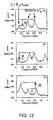
- Fig. 12 is an explanatory diagram for explaining a heterodyne beat spectrum of FWM light.
- a frequency difference between a local oscillator and an FWM light carrier is set to approximately 100 MHz.
- a 100 MHz component indicates an FWM light carrier, and both a 400 MHz component and a 600 MHz component represent primary sidebands of ⁇ 500 MHz.
- a 900 MHz component corresponds to a second order sideband.
- Fig. 12 (a) shows such a heterodyne beat spectrum obtained in the case that only pumping light is phase-modulated. In this case, a carrier is suppressed, and a large sideband component appears.
- a strength ratio of the carrier to the primary sideband is set to "R"
- this strength ratio "R” is equal to -10.5 dB in this example.
- Fig. 12 (b) and Fig. 12 (c) show heterodyne beat spectra in the case that both the pumping light and the signal light are phase-modulated.
- Fig. 13 is an explanatory diagram for explaining a sideband suppression ratio when a modulation index ratio is changed.
- An horizontal axis of Fig. 13 shows a modulation index ratio of m s /m p
- an vertical axis of Fig. 13 represents the sideband suppression ratio "R" as explained in the previous item.
- the sideband suppression ratio "R” becomes large, so that the trend in the experimental result is made substantially coincident with the trend in the theoretical value. It is so conceivable that if a phase of an applied voltage is further strictly adjusted, then the experimental result may be approached to the theoretical value. It should be understood that since the strength ratio "R” is such a value depending upon the primary sideband, there are same possibilities that the large strength ratio "R” may be obtained even by another modulation index ratio. At this time, although the primary sideband is decreased, higher-order sidebands are produced and a spectrum of produced phase conjugate light is broadened. A care should be taken to such a fact that when the modulation index ratio is equal to 2, a completely different condition occurs.
- a wavelength conversion operation which does not depend upon a polarized wave of signal light, may be realized in such a manner that polarized waves of pumping light having different wavelengths are entered into an optical fiber in such a manner that these polarized waves are orthogonal to each other by a polarization beam splitter (PBS) by employing two sets of pumping light (orthogonal polarization two-wavelength pumping system) (see S. Yamashita, S.Y.Set, and R.I.Laming, "Polarization independent, all-fiber phase conjugation incorporating inline fiber DFB lasers, "IEEE Photonics Technology Letters , vol.10, no.10, pp.1407-1409, Oct. 1998 ).
- the comparative example wavelength conversion apparatus is provided with polarization controllers (PCs) 101, 104, 142; phase modulators (PMs) 105, 143; laser diodes (LDs) 103, 141; a coupler 106; an Eribuim-doped fiber amplifier (EDFA) 107; a dispersion-shifted fiber (DSF) 108; a band-pass filter (BPF) 109; an oscillator 110; and a polarization beam splitter (PBS) 144.
- PCs polarization controllers
- PMs phase modulators
- LDs laser diodes
- a coupler 106 an Eribuim-doped fiber amplifier
- DSF dispersion-shifted fiber
- BPF band-pass filter
- PBS polarization beam splitter
- the laser diode (LD) 141 corresponds to a light emitting unit for outputting pumping light (Pump).
- the polarization controller (PC) 142 controls a polarization plane of input light.
- the phase modulator (PM) 143 phase-modulates the pumping light (Pump) based upon a modulation signal outputted from the oscillator 110, and then, outputs the phase-modulated pumping light.
- the polarization beam splitter (PBS) 144 splits input light to polarized waves which are orthogonal to each other, and multiplexes these polarized waves with each other.
- Other structural elements of this wavelength conversion apparatus are similar to those of Fig. 2 .
- the light outputted from the phase modulator (PM) 105 and the light outputted from the phase modulator (PM) 143 are multiplexed with each other by the polarization beam splitter (PBS) 144 in such a manner that the polarized planes thereof are orthogonal with each other.
- PBS polarization beam splitter
- the signal light traveled through the polarization controller (PC) 101 is multiplexed with the light outputted from the polarization beam splitter (PBS) 144.
- both the signal light and the pumping light which have been multiplexed with each other, are amplified by the Erbium-doped fiber amplifier (EDFA) 107, and thereafter, the amplified signal and pumping light are processed by the dispersion-shifted fiber (DSF) 108 and the band-pass filter (BPF) 109, so that FWM light is outputted.
- EDFA Erbium-doped fiber amplifier
- DSF dispersion-shifted fiber
- BPF band-pass filter
- symbols "E p1 " and “E p2 " indicate optical electric fields of first and second pumping light, respectively.
- the angular frequency " ⁇ FWM” of the fourth light may be obtained as “ ⁇ ijk ", assuming now that in the formula (3), for instance, symbol “ ⁇ i “ is the angular frequency "w p1 " of the first pumping light; symbol “ ⁇ j “ is the angular frequency “ ⁇ p2 “ of the second pumping light; and symbol “ ⁇ k “ is the angular frequency " ⁇ s " of the signal light. It should also be understood that plural sets of corresponding relationships other than this relationship may be conceived.
- Fig. 15 is a structural diagram for indicating another Comparative example wavelength conversion apparatus.
- This drawing represents such an arrangement that both two sets of pumping light are frequency-modulated in the orthogonal polarization two-wavelength pumping system.
- a wavelength conversion operation which does not depend upon a polarized wave of signal light, may be realized in such a manner that polarized waves of pumping light having different wavelengths are entered into an optical fiber in such a manner that these polarized waves are orthogonal to each other by a polarization beam splitter (PBS) by employing two sets of pumping light.
- PBS polarization beam splitter
- the wavelength conversion apparatus of this embodiment mode is provided with polarization controllers (PCs) 101, 104, 152; laser diodes (LDs) 401, 151; a coupler 106; an Eribuim-doped fiber amplifier (EDFA) 107; a dispersion-shifted fiber (DSF) 108; a band-pass filter (BPF) 109; an oscillator 110; and a polarization beam splitter (PBS) 153.
- PCs polarization controllers
- LDs laser diodes
- DSF dispersion-shifted fiber
- BPF band-pass filter
- PBS polarization beam splitter
- the laser diode (LD) 151 corresponds to a light emitting unit for frequency-modulating pumping light based upon a modulation signal outputted from the oscillator 110 to output the frequency-modulated pumping light.
- the polarization controller (PC) 152 controls a polarization plane of input light.
- the polarization beam splitter (PBS) 153 splits input light to polarized waves which are orthogonal to each other, and multiplexes polarized waves with each other. Other structural elements of this wavelength conversion apparatus are similar to those of Fig. 4 .
- the pumping light is directly frequency-modulated by the laser diodes (LDs) 401 and 151 based upon the modulation signal outputted from the oscillator 110, and then, the frequency-modulated pumping light passes through the polarization controllers (PCs) 104 and 152.
- the light outputted from the phase modulator (PM) 105 and the light outputted from the phase modulator (PM) 143 are multiplexed with each other by the polarization beam splitter (PBS) 144 in such a manner that the polarized planes thereof are orthogonal with each other.
- the signal light traveled through the polarization controller (PC) 101 is multiplexed with the light outputted from the polarization beam splitter (PBS) 144.
- both the signal light and the pumping light which have been multiplexed with each other, are amplified by the Erbium-doped fiberamplifier (EDFA) 107, and thereafter, the amplified signal and pumping light is processed by the dispersion-shifted fiber (DSF) 108 and the band-pass filter (BPF) 109, so that FWM light is outputted.
- EDFA Erbium-doped fiberamplifier
- the angular frequency " ⁇ FWM” of the fourth light may be obtained as “ ⁇ ijk ", assuming now that in the formula (3), for instance, symbol “ ⁇ i “ is the angular frequency " ⁇ p1 " of the first pumping light; symbol “ ⁇ j “ is the angular frequency “ ⁇ p2 “ of the second pumping light; and symbol “ ⁇ k “ is the angular frequency " ⁇ s " of the signal light. It should also be understood that plural sets of corresponding relationships other than this relationship may be conceived.
- the wavelength conversion apparatus having the high conversion efficiency with employment of the optical fiber can be provided. More specifically, in accordance with the present invention, while the SBS phenomenon is suppressed by phase-modulating, or frequency-modulating the pumping light, the signal light is also phase-modulated based upon the same frequency, so that the FWM light having less broadening of the spectrum.
Landscapes
- Physics & Mathematics (AREA)
- Nonlinear Science (AREA)
- General Physics & Mathematics (AREA)
- Optics & Photonics (AREA)
- Optical Modulation, Optical Deflection, Nonlinear Optics, Optical Demodulation, Optical Logic Elements (AREA)
- Optical Communication System (AREA)
Claims (6)
- Wellenlängenübersetzungsvorrichtung, umfassend
einen Oszillator (110), der zur Auskopplung eines Modulationssignals ausgebildet ist;
einen ersten Phasen-Modulator (102) zur Einkopplung eines Lichtsignals in diesen und zur Phasen-Modulation eines des Lichtsignals mittels des aus dem Osziallator (110) ausgekoppelten Modulationssignals;
einen zweiten Phasen-Modulator (105), ausgebildet zur Phasen-Modulation eines eingekoppelten Pumplichts;
einen Multiplexer (106) zur Bündelung des Ausgangs des ersten Phasen-Modulators und des Ausgangs des zweiten Phasen-Modulator; und
eine optische Faser (108), ausgebildet zur Einkopplung des Ausgangs des Multiplexers in diese, und ausgebildet zur Auskopplung eines optischen Signals, wobei die Wellenlänge des optischen Signals in der optischen Faser mittels eines Vier-Wellen-Mischprozesses gewandelt wird;
dadurch gekennzeichnet, dass:der zweite Phasen-Modulator zur Phasen-Modulation des eingekoppelten Pumplichts synchron mit dem Lichtsignal des Modulationssignals ausgebildet ist; unddie Phasen-Modulation des Lichtsignals durch den ersten Phasen-Modulator (102) und die Phasen-Modulation des Pumplichts durch den zweiten Phasen-Modulator (105) folgenden Bedingungen genügen:

mitmp : Modulationsindex des Pumplichts,ms : Modulationsindex des Lichtsignals,ω m : Kreisfrequenz der Modulation,τ : Zeitverzögerung zwischen beiden phasen-modulierten Signalen,n : Ganze Zahlϕ : Phasendifferenz zwischen den Modulationssignalen der ersten und zweiten Phasen-Modulation. - Wellenlängenübersetzungsvorrichtung, umfassend
einen Oszillator (110), ausgebildet zur Auskopplung eines Modulationssignals;
einen ersten Phasen-Modulator (105), ausgebildet zur Einkopplung eines Pumplichts in diesen und ausgebildet zur Phasen-Modulation des Pumplichts mittels des Modulationssignals des Oszillators;
ein Multiplexer (106), ausgebildet zur Bündelung des Ausgangs des ersten Phasen-Modulators und eines Lichtsignals, und
eine optische Faser (108), ausgebildet zur Einkopplung des Ausgangs des Multiplexers in diese, und ausgebildet zur Ausgabe eines optischen Signals, wobei die Wellenlänge des optischen Signals in der optischen Faser mittels eines Vier-Wellen-Mischprozesses gewandelt wird;
dadurch gekennzeichnet, dass:die Wellenübersetzungsvorrichtung ferner einen zweiten Phasen-Modulator (301) umfasst, der ausgebildet ist, die Phase des aus der optischen Faser ausgekoppelten vier-wellengemischten Lichts synchron mit dem Pumplicht mittels des Modulationssignals zu modulieren; unddie Phasen-Modulation des Pumplichts durch den ersten Phasen-Modulator (105) und die Phasen-Modulation des vier-wellen-gemischten Lichts durch den zweiten Phasen-Modulator (301) den folgenden Bedingungen genügen:

mitmp : Modulationsindex des Pumplichts,ms : Modulationsindex des vier-wellengemischten Lichts,ωm : Kreisfrequenz der Modulation,τ : Zeitverzögerung zwischen beiden phasen-modulierten Signalen,n : Ganze Zahlϕ : Phasendifferenz zwischen den Modulationssignalen des ersten und zweiten Phasen-Modulators. - Wellenlängenübersetzungsvorrichtung, umfassend
einen Oszillator (110), ausgebildet zur Auskopplung eines Modulationssignals;
einen Phasen-Modulator (102), ausgebildet zur Einkopplung eines Lichtsignals in diesen, und ausgebildet zur Phasen-Modulation des Lichtsignals mittels des aus dem Oszillator ausgekoppelten Modulationssignals;
eine licht-emittierende Vorrichtung (401), ausgebildet zur Auskopplung eines Pumplichts, das frequenz-moduliert ist;
einen Multiplexer (106), ausgebildet zum Bündeln des Ausgangs des Phasen-Modulators und des Ausgangs der licht-emittierenden Vorrichtung; und
eine optische Faser (108), ausgebildet zur Einkopplung des Ausgangs des Multiplexers in diese, und ausgebildet zur Auskopplung eines optischen Signals, wobei die Wellenlänge des optischen Signals in der optischen Faser mittels eines Vier-Wellen-Mischprozesses gewandelt wird;
dadurch gekennzeichnet, dass
die licht-emittierende Vorrichtung (401) zur Auskopplung des Pumplichts ausgebildet ist, wobei das Pumplicht durch das Modulationssignal synchron mit dem Lichtsignal frequenz-moduliert wird; und
das Modulationssignal folgenden Bedingungen genügt:

mitB : Maximale Frequenz-Abweichung des Pumplichts,ω m : Kreisfrequenz der Modulation,ms : Modulationsindex des Lichtsignals,τ : Zeitverzögerung zwischen beiden phasen-modulierten Signalenn : Ganze Zahl - Wellenlängenübersetzungsvorrichtung, umfassend
einen Oszillator (110), ausgebildet zur Auskopplung eines Modulationssignals;
einen Phasen-Modulator (102), ausgebildet zur Einkopplung eines Lichtsignals in diesen in eine erste Richtung und ausgebildet zur Phasen-Modulation des Lichtsignals durch das ausgekoppelte Modulationssignal des Oszillators;
einen Reflektor (502) zur Reflektion des Lichtsignals, das in die erste Richtung eingekoppelt ist, in eine zweite Richtung; und
einen Multiplexer (106), ausgebildet zur Bündelung des Pumplichts und des vom Reflektor reflektierten Lichtsignals;
dadurch gekennzeichnet, dass
der Phasen-Modulator (102) ferner zur Einkopplung des gebündelten Lichts aus dem Multiplexer in einer zweiten Richtung und zum Modulieren der Phase des Pumplichts und des in einer zweiten Richtung phasen-modulierten Lichtsignals synchron mit dem Lichtsignal entlang der ersten Richtung mittels des Modulationssignals und zur Ausgabe des phasenmodulierten Lichtsignals und des Pumplichts entlang der zweiten Richtung ausgebildet ist,;
und, dass die Wellenlängenübersetzungsvorrichtung ferner eine optische Faser (108), ausgebildet zur Einkopplung des Ausgangs des Phasen-Modulator und zur Auskopplung eines optischen Signals umfasst, wobei die Wellenlänge des optischen Signals in der optischen Faser mittels eines Vier-Wellen-Mischprozesses gewandelt wird; und
das Modulationssignal der folgenden Bedingung genügt:
mitω m : Kreisfrequenz der Modulation,τ : Zeitverzögerung zwischen dem Phasenmodulator und dem Spiegel,n : Ganze Zahl. - Wellenlängenübersetzungsvorrichtung gemäß Anspruch 1 oder 2, umfassend:Eine Polarisations-Steuervorrichtung (101, 104, 111), ausgebildet zur Steuerung der Polarisation von Licht, das in die optische Faser, den ersten oder zweiten Phasen-Modulator eingekoppelt wird.
- Wellenlängenübersetzungsvorrichtung gemäß Anspruch 3 oder 4, umfassend:Eine Polarisations-Steuervorrichtung (101, 104), ausgebildet zur Steuerung der Polarisation des Lichts, das in die optische Faser oder den Phasen-Modulator eingekoppelt wird.
Applications Claiming Priority (3)
| Application Number | Priority Date | Filing Date | Title |
|---|---|---|---|
| JP2000202859 | 2000-07-04 | ||
| JP2000202859A JP3401483B2 (ja) | 2000-07-04 | 2000-07-04 | 波長変換装置 |
| PCT/JP2000/006867 WO2002003132A1 (en) | 2000-07-04 | 2000-10-03 | Wavelength converter |
Publications (3)
| Publication Number | Publication Date |
|---|---|
| EP1306718A1 EP1306718A1 (de) | 2003-05-02 |
| EP1306718A4 EP1306718A4 (de) | 2005-08-17 |
| EP1306718B1 true EP1306718B1 (de) | 2012-06-06 |
Family
ID=18700328
Family Applications (1)
| Application Number | Title | Priority Date | Filing Date |
|---|---|---|---|
| EP00963066A Expired - Lifetime EP1306718B1 (de) | 2000-07-04 | 2000-10-03 | Wellenlängenumsetzer |
Country Status (4)
| Country | Link |
|---|---|
| US (1) | US6879433B1 (de) |
| EP (1) | EP1306718B1 (de) |
| JP (1) | JP3401483B2 (de) |
| WO (1) | WO2002003132A1 (de) |
Families Citing this family (39)
| Publication number | Priority date | Publication date | Assignee | Title |
|---|---|---|---|---|
| JP3401483B2 (ja) * | 2000-07-04 | 2003-04-28 | 科学技術振興事業団 | 波長変換装置 |
| WO2003036354A2 (en) * | 2001-10-25 | 2003-05-01 | Lambda Crossing Ltd. | Polarization insensitive tunable optical filters |
| US20040057734A1 (en) * | 2002-09-25 | 2004-03-25 | Lucent Technologies, Inc. | Method and system for reducing transmission penalties associated with ghost pulses |
| US7146110B2 (en) | 2003-02-11 | 2006-12-05 | Optium Corporation | Optical transmitter with SBS suppression |
| JP2004287382A (ja) * | 2003-03-20 | 2004-10-14 | Sumitomo Electric Ind Ltd | 波長変換器 |
| US20040212872A1 (en) * | 2003-03-25 | 2004-10-28 | Jean-Luc Auge | Optical signal processing system and method |
| JP3963272B2 (ja) * | 2003-05-22 | 2007-08-22 | 日本電信電話株式会社 | 光周波数変換装置 |
| US7145715B2 (en) * | 2004-09-23 | 2006-12-05 | Lucent Technologies Inc. | Multiple pump parametric apparatus having no idler broadening |
| US7555221B2 (en) * | 2004-12-23 | 2009-06-30 | Alcatel-Lucent Usa Inc. | Method and apparatus for polarization-independent RF spectrum analysis of an optical source |
| DE102005054379B4 (de) * | 2005-11-15 | 2013-08-22 | Deutsche Telekom Ag | Verfahren und System zur Verstärkung von Licht in optischen Fasern |
| JP5064752B2 (ja) | 2006-03-29 | 2012-10-31 | 古河電気工業株式会社 | 光パルス列発生器 |
| US20070258717A1 (en) * | 2006-05-01 | 2007-11-08 | Masaaki Hirano | Optical device and wavelength conversion method and optical fiber suitable for them |
| KR20090031732A (ko) * | 2006-07-20 | 2009-03-27 | 가부시키가이샤 니콘 | 광화이버 증폭기, 광원 장치, 노광 장치, 피검사물 검사 장치 및 가공 장치 |
| JP4640420B2 (ja) * | 2008-02-29 | 2011-03-02 | 沖電気工業株式会社 | 波長変換装置及び波長変換方法 |
| JP5213125B2 (ja) * | 2008-05-29 | 2013-06-19 | ニューブレクス株式会社 | 分布型光ファイバセンサ |
| US20100284054A1 (en) * | 2009-05-08 | 2010-11-11 | Honeywell International Inc. | Modulation of unpolarized light |
| US8279516B2 (en) * | 2010-01-28 | 2012-10-02 | Oki Electric Industry Co., Ltd. | Wavelength conversion device and wavelength conversion method |
| US20130058652A1 (en) * | 2010-05-14 | 2013-03-07 | France Telecom | Optical line termination device allowing the implementation of an ofdm modulation technique |
| DE102010055284A1 (de) * | 2010-12-21 | 2012-06-21 | Friedrich-Schiller-Universität Jena | Effiziente Frequenzkonversion |
| US8571417B2 (en) * | 2011-04-13 | 2013-10-29 | Cisco Technology, Inc. | System and method for mitigating four-wave-mixing effects |
| US8611759B1 (en) * | 2012-02-07 | 2013-12-17 | The United States Of America As Represented By The Secretary Of The Navy | Optical domain wideband RF spectrum analyzer/channelizer based on third-order nonlinear mixing |
| US8976445B1 (en) * | 2012-03-02 | 2015-03-10 | University Of Southern California | Optical tunable tapped-delay-lines using wavelength conversion and chromatic dispersion based delays |
| WO2014043590A1 (en) * | 2012-09-13 | 2014-03-20 | California Institute Of Technology | Optically balanced opto-electrical oscillator |
| EP3115840B1 (de) * | 2014-03-04 | 2020-05-06 | National Institute of Advanced Industrial Science and Technology | Verfahren und vorrichtung zur optischen phasenregenerierung |
| JP6353342B2 (ja) * | 2014-10-19 | 2018-07-04 | 国立研究開発法人情報通信研究機構 | 光アップ・ダウンコンバート型光位相共役対信号送受信回路 |
| CN104375148B (zh) * | 2014-11-14 | 2017-01-18 | 上海理工大学 | 一种基于线性灵敏光子探测器的近红外激光测距方法 |
| US10411810B2 (en) | 2016-07-04 | 2019-09-10 | The Regents Of The University Of California | Receiver with mutually coherent optical frequency combs |
| US10523329B2 (en) | 2016-11-07 | 2019-12-31 | The Regents Of The University Of California | Comb-assisted cyclostationary analysis |
| JP6719414B2 (ja) * | 2017-03-29 | 2020-07-08 | 古河電気工業株式会社 | 位相共役光発生装置及び光通信システム、並びに位相共役光発生方法 |
| JP6911483B2 (ja) * | 2017-04-19 | 2021-07-28 | 富士通株式会社 | 波長変換装置、制御光生成装置、波長変換方法、および制御光生成方法 |
| WO2019010439A1 (en) | 2017-07-07 | 2019-01-10 | The Regents Of The University Of California | SYSTEM AND METHOD FOR ENHANCING SENSITIVITY OF A RECEIVER |
| JP7106835B2 (ja) | 2017-10-06 | 2022-07-27 | 富士通株式会社 | 光伝送装置、波長変換装置、光伝送方法、および波長変換方法 |
| US10790911B2 (en) * | 2018-04-10 | 2020-09-29 | The University Of Massachusetts | Modified Sagnac loop coherent phase modulated RF photonic link |
| JP7222255B2 (ja) * | 2019-01-28 | 2023-02-15 | 富士通株式会社 | 波長変換装置及び波長変換方法 |
| JP7693399B2 (ja) * | 2021-06-01 | 2025-06-17 | Kddi株式会社 | 光角度変調器及び光送信装置 |
| JP7467398B2 (ja) * | 2021-09-06 | 2024-04-15 | Kddi株式会社 | 光変調器及び光送信装置 |
| CN114355696B (zh) * | 2022-01-10 | 2024-05-07 | 湖南师范大学 | 基于光纤环串扰消除的偏振复用信号波长变换装置及方法 |
| DE102022121510B3 (de) * | 2022-08-25 | 2023-11-30 | Tesat-Spacecom Gmbh & Co. Kg | Selbstkompensierender Polarisationsmodulator mit direktionalem Phasenschieber, optische Signalübertragungsstrecke und Satellit |
| CN117614541B (zh) * | 2024-01-24 | 2024-03-26 | 华北电力大学(保定) | 光纤射频信号稳定传输系统及方法 |
Family Cites Families (4)
| Publication number | Priority date | Publication date | Assignee | Title |
|---|---|---|---|---|
| US5386314A (en) * | 1993-09-10 | 1995-01-31 | At&T Corp. | Polarization-insensitive optical four-photon mixer with orthogonally-polarized pump signals |
| JPH0895093A (ja) * | 1994-09-26 | 1996-04-12 | Nippon Telegr & Teleph Corp <Ntt> | 波長変換装置 |
| US6307984B1 (en) * | 1996-08-22 | 2001-10-23 | Fujitsu Limited | Optical fiber communication system using optical phase conjugation as well as apparatus applicable to the system and method of producing the same |
| JP3401483B2 (ja) * | 2000-07-04 | 2003-04-28 | 科学技術振興事業団 | 波長変換装置 |
-
2000
- 2000-07-04 JP JP2000202859A patent/JP3401483B2/ja not_active Expired - Fee Related
- 2000-10-03 US US10/332,028 patent/US6879433B1/en not_active Expired - Fee Related
- 2000-10-03 WO PCT/JP2000/006867 patent/WO2002003132A1/ja not_active Ceased
- 2000-10-03 EP EP00963066A patent/EP1306718B1/de not_active Expired - Lifetime
Also Published As
| Publication number | Publication date |
|---|---|
| EP1306718A4 (de) | 2005-08-17 |
| JP3401483B2 (ja) | 2003-04-28 |
| EP1306718A1 (de) | 2003-05-02 |
| US6879433B1 (en) | 2005-04-12 |
| JP2002023210A (ja) | 2002-01-23 |
| WO2002003132A1 (en) | 2002-01-10 |
Similar Documents
| Publication | Publication Date | Title |
|---|---|---|
| EP1306718B1 (de) | Wellenlängenumsetzer | |
| EP2672318B1 (de) | Optischer verstärker | |
| US6178036B1 (en) | Opto-electronic devices and systems based on brillouin selective sideband amplification | |
| Yao | Microwave photonics | |
| US9698913B2 (en) | System and method for distortion correction in phase-encoded photonic links | |
| EP3064956A1 (de) | Vollständig optisch gesteuerter phasengeregelter radarsender | |
| US6333803B1 (en) | Optical transmitter | |
| Waarts et al. | Nonlinear effects in coherent multichannel transmission through optical fibers | |
| US8494378B2 (en) | Synchronous optical signal generating device and synchronous optical signal generating method | |
| JPH03130723A (ja) | レーザー通信システム内のハーモニック歪を低減するための干渉計デバイス | |
| Adams et al. | A novel broadband photonic RF phase shifter | |
| JP3903235B2 (ja) | 可変波長四光波混合器 | |
| CA2351265C (en) | Optical frequency converter using reciprocating modulation | |
| US7346083B2 (en) | Bandwidth enhanced self-injection locked DFB laser with narrow linewidth | |
| Ganjali et al. | Microwave photonic frequency multiplication based on Sagnac interferometer with the capability of phase shifting | |
| Djupsjobacka et al. | Dispersion compensation by differential time delay | |
| JP5435443B2 (ja) | 同期光信号発生装置及び同期光信号発生方法 | |
| WO2006004133A1 (ja) | 多波長光源、及び多波長光の発生方法 | |
| Cabon et al. | 2.3. OPTICAL GENERATION OF MICROWAVE FUNCTIONS | |
| Guo et al. | Flexible multi-band dual-chirped microwave waveform generator based on a recirculating frequency shifting loop | |
| Contestabile et al. | Polarization-and interval-independent wavelength conversion at 2.5 Gb/s by means of bidirectional four-wave mixing in semiconductor optical amplifiers | |
| Bui et al. | All optical instantaneous frequency measurement incorporating optical Hilbert transformer | |
| Madsen et al. | A tunable ultra-narrowband filter for subcarrier processing and optical monitoring | |
| Li et al. | Stable and wideband-tunable optoelectronic oscillator utilizing a narrow-passband microwave photonic filter | |
| Lima et al. | Tunable Optical Frequency Comb Generation Applied to DWDM and 5G Networks |
Legal Events
| Date | Code | Title | Description |
|---|---|---|---|
| PUAI | Public reference made under article 153(3) epc to a published international application that has entered the european phase |
Free format text: ORIGINAL CODE: 0009012 |
|
| 17P | Request for examination filed |
Effective date: 20030114 |
|
| AK | Designated contracting states |
Designated state(s): DE FR GB |
|
| AX | Request for extension of the european patent |
Extension state: AL LT LV MK RO SI |
|
| RAP1 | Party data changed (applicant data changed or rights of an application transferred) |
Owner name: JAPAN SCIENCE AND TECHNOLOGY AGENCY |
|
| A4 | Supplementary search report drawn up and despatched |
Effective date: 20050630 |
|
| GRAP | Despatch of communication of intention to grant a patent |
Free format text: ORIGINAL CODE: EPIDOSNIGR1 |
|
| GRAS | Grant fee paid |
Free format text: ORIGINAL CODE: EPIDOSNIGR3 |
|
| GRAA | (expected) grant |
Free format text: ORIGINAL CODE: 0009210 |
|
| AK | Designated contracting states |
Kind code of ref document: B1 Designated state(s): DE FR GB |
|
| REG | Reference to a national code |
Ref country code: GB Ref legal event code: FG4D |
|
| REG | Reference to a national code |
Ref country code: DE Ref legal event code: R096 Ref document number: 60047250 Country of ref document: DE Effective date: 20120802 |
|
| PLBE | No opposition filed within time limit |
Free format text: ORIGINAL CODE: 0009261 |
|
| STAA | Information on the status of an ep patent application or granted ep patent |
Free format text: STATUS: NO OPPOSITION FILED WITHIN TIME LIMIT |
|
| 26N | No opposition filed |
Effective date: 20130307 |
|
| REG | Reference to a national code |
Ref country code: DE Ref legal event code: R097 Ref document number: 60047250 Country of ref document: DE Effective date: 20130307 |
|
| PGFP | Annual fee paid to national office [announced via postgrant information from national office to epo] |
Ref country code: GB Payment date: 20131002 Year of fee payment: 14 Ref country code: FR Payment date: 20131009 Year of fee payment: 14 Ref country code: DE Payment date: 20130925 Year of fee payment: 14 |
|
| REG | Reference to a national code |
Ref country code: DE Ref legal event code: R119 Ref document number: 60047250 Country of ref document: DE |
|
| GBPC | Gb: european patent ceased through non-payment of renewal fee |
Effective date: 20141003 |
|
| PG25 | Lapsed in a contracting state [announced via postgrant information from national office to epo] |
Ref country code: DE Free format text: LAPSE BECAUSE OF NON-PAYMENT OF DUE FEES Effective date: 20150501 Ref country code: GB Free format text: LAPSE BECAUSE OF NON-PAYMENT OF DUE FEES Effective date: 20141003 |
|
| REG | Reference to a national code |
Ref country code: FR Ref legal event code: ST Effective date: 20150630 |
|
| PG25 | Lapsed in a contracting state [announced via postgrant information from national office to epo] |
Ref country code: FR Free format text: LAPSE BECAUSE OF NON-PAYMENT OF DUE FEES Effective date: 20141031 |