EP1306603B1 - Process and device for controlling a safety-relevant function of a machine - Google Patents
Process and device for controlling a safety-relevant function of a machine Download PDFInfo
- Publication number
- EP1306603B1 EP1306603B1 EP02021518A EP02021518A EP1306603B1 EP 1306603 B1 EP1306603 B1 EP 1306603B1 EP 02021518 A EP02021518 A EP 02021518A EP 02021518 A EP02021518 A EP 02021518A EP 1306603 B1 EP1306603 B1 EP 1306603B1
- Authority
- EP
- European Patent Office
- Prior art keywords
- safety
- machine
- region
- movement
- danger
- Prior art date
- Legal status (The legal status is an assumption and is not a legal conclusion. Google has not performed a legal analysis and makes no representation as to the accuracy of the status listed.)
- Expired - Lifetime
Links
Images


Classifications
-
- F—MECHANICAL ENGINEERING; LIGHTING; HEATING; WEAPONS; BLASTING
- F16—ENGINEERING ELEMENTS AND UNITS; GENERAL MEASURES FOR PRODUCING AND MAINTAINING EFFECTIVE FUNCTIONING OF MACHINES OR INSTALLATIONS; THERMAL INSULATION IN GENERAL
- F16P—SAFETY DEVICES IN GENERAL; SAFETY DEVICES FOR PRESSES
- F16P3/00—Safety devices acting in conjunction with the control or operation of a machine; Control arrangements requiring the simultaneous use of two or more parts of the body
- F16P3/12—Safety devices acting in conjunction with the control or operation of a machine; Control arrangements requiring the simultaneous use of two or more parts of the body with means, e.g. feelers, which in case of the presence of a body part of a person in or near the danger zone influence the control or operation of the machine
- F16P3/14—Safety devices acting in conjunction with the control or operation of a machine; Control arrangements requiring the simultaneous use of two or more parts of the body with means, e.g. feelers, which in case of the presence of a body part of a person in or near the danger zone influence the control or operation of the machine the means being photocells or other devices sensitive without mechanical contact
- F16P3/144—Safety devices acting in conjunction with the control or operation of a machine; Control arrangements requiring the simultaneous use of two or more parts of the body with means, e.g. feelers, which in case of the presence of a body part of a person in or near the danger zone influence the control or operation of the machine the means being photocells or other devices sensitive without mechanical contact using light grids
-
- F—MECHANICAL ENGINEERING; LIGHTING; HEATING; WEAPONS; BLASTING
- F16—ENGINEERING ELEMENTS AND UNITS; GENERAL MEASURES FOR PRODUCING AND MAINTAINING EFFECTIVE FUNCTIONING OF MACHINES OR INSTALLATIONS; THERMAL INSULATION IN GENERAL
- F16P—SAFETY DEVICES IN GENERAL; SAFETY DEVICES FOR PRESSES
- F16P3/00—Safety devices acting in conjunction with the control or operation of a machine; Control arrangements requiring the simultaneous use of two or more parts of the body
- F16P3/12—Safety devices acting in conjunction with the control or operation of a machine; Control arrangements requiring the simultaneous use of two or more parts of the body with means, e.g. feelers, which in case of the presence of a body part of a person in or near the danger zone influence the control or operation of the machine
- F16P3/14—Safety devices acting in conjunction with the control or operation of a machine; Control arrangements requiring the simultaneous use of two or more parts of the body with means, e.g. feelers, which in case of the presence of a body part of a person in or near the danger zone influence the control or operation of the machine the means being photocells or other devices sensitive without mechanical contact
- F16P3/142—Safety devices acting in conjunction with the control or operation of a machine; Control arrangements requiring the simultaneous use of two or more parts of the body with means, e.g. feelers, which in case of the presence of a body part of a person in or near the danger zone influence the control or operation of the machine the means being photocells or other devices sensitive without mechanical contact using image capturing devices
Abstract
Description
Die Erfindung betrifft Verfahren zum Steuern wenigstens einer sicherheitsrelevanten Funktion einer Maschine, bei dem ein Überwachungsbereich von wenigstens einem Sensor überwacht wird und eine Position eines Objektes erkannt wird und der Überwachungsbereich eine einen Gefahrenbereich abgrenzende Sicherheitsgrenze umfasst, die einen Sicherheitsabstand zu einer Gefahrstelle der Maschine definiert, und ein Eindringen in den Gefahrenbereich die sicherheitsrelevante Funktion auslöst. Die Erfindung betrifft ferner eine Vorrichtung zur Durchführung der Verfahren.The invention relates to methods for controlling at least one safety-related function of a machine in which a surveillance area is monitored by at least one sensor and a position of an object is detected and the monitoring area a includes a safety margin delimiting a danger area, a safety distance to a hazardous point of the Machine defines, and penetration into the danger area the safety relevant Function triggers. The invention further relates to a device for Implementation of the procedures.
Um Bedienpersonen von Maschinen, die ein Gefahrpotenzial bergen, wie beispielsweise Pressen, insbesondere Gesenkbiegepressen, Roboter oder dergleichen, zu schützen, sind verschiedene Sicherheitseinrichtungen bekannt.To operators of machines, which hold a danger potential, like for example, presses, in particular press bending presses, robots or Like, various safety devices are known.
So wird beispielsweise in einfachster Weise ein Schutz dadurch bereitgestellt, dass ein Zutritt zu oder ein Eingriff in einen Gefahrenbereich mechanisch, beispielsweise durch Gitter oder Sperrzäune, abgesichert ist. Eine mechanische Absicherung erschwert jedoch den Zugang zur Maschine auch während eines Maschinenstillstandes, so dass heutzutage bevorzugt optoelektronische Schutzeinrichtungen eingesetzt werden. Thus, for example, protection is provided in the simplest way by an access to or an intervention in a danger area mechanically, for example secured by grating or barrier fences. A mechanical protection However, it also makes access to the machine difficult during one Machine downtime, so that today optoelectronic preferred Protective devices are used.
Hierbei kann es sich um ein Lichtgitter handeln, das eine optische Zugangssicherung bildet, so dass beim Durchtritt durch das Lichtgitter eine sicherheitsrelevante Funktion der Maschine, beispielsweise ein Anhalten der Maschine, ausgelöst wird.This can be a light grid that has an optical Secure access forms, so that when passing through the light grid a safety-relevant function of the machine, for example stopping the Machine, is triggered.
Weitere optoelektronische Schutzeinrichtungen sind aus der WO 97/25568 und der WO 00/67932 bekannt, die ein Verfahren und eine Vorrichtung der eingangs genannten Art zeigen. Zum Fingerschutz an Gesenkbiegepressen werden dort einzelne Lichtschranken unmittelbar in der Nähe des Biegewerkzeugs angeordnet, so dass im Prinzip ein Zugang zur Presse gewährleistet ist und lediglich der gefährliche Bereich in unmittelbarer Nähe der Presswerkzeuge durch die Lichtschranken geschützt ist.Further optoelectronic protective devices are known from WO 97/25568 and the WO 00/67932 known, a method and an apparatus of the aforementioned Show kind. Finger protection on press brakes will be there individual light barriers are arranged directly in the vicinity of the bending tool, so that in principle access to the press is guaranteed and only the dangerous area in the immediate vicinity of the pressing tools through the Photocells is protected.
Allen diesen optoelektronischen Schutzsystemen ist gemeinsam, dass die Grenze zwischen dem abzusichernden Gefahrenbereich und dem gefahrlosen Bereich durch einen Mindestabstand zur gefahrbringenden Bewegung der Maschine fest definiert ist und bei Überschreiten dieser Grenze die sicherheitsrelevante Funktion, was zumeist ein Anhalten der Maschine bedeutet, ausgelöst wird. Da die Maschine eine gewisse Nachlaufzeit bzw. Nachlaufweg hat und die Geschwindigkeit des Objektes, das in den Gefahrenbereich eindringt, unbekannt ist, müssen die Schutzeinrichtungen (z.B. Lichtschranken und Lichtgitter) einen ausreichenden Abstand zur eigentlichen Gefahrenstelle haben. Es muss beispielsweise sichergestellt sein, dass auch bei einer sehr schnellen Bewegung, beispielsweise bei einem Sturz der Bedienperson, die Maschine noch rechtzeitig zum Stillstand kommt, bevor die Person in irgendeiner Weise mit dem Gefahrenbereich der Maschine in Berührung kommen könnte. Dabei kann von der Sicherheitseinrichtung nicht zwischen langsamen und vorsichtigen Bewegungen der Bedienperson und unvorsichtigen, unter Umständen schnellen Bewegungen, die ein höheres Unfallpotenzial haben, unterschieden werden. Aus Sicherheitsgründen ist dann immer die sicherheitsrelevante Funktion ausgelöst.All these optoelectronic protection systems have in common that the limit between the danger area to be protected and the safe area by a minimum distance to the dangerous movement of the machine is defined and if this limit is exceeded, the safety-relevant function, which usually means stopping the machine is triggered. Because the machine has a certain overrun time or overrun and the speed of the Object that enters the danger area is unknown, the Protective devices (e.g., photoelectric sensors and light curtains) provide sufficient Distance to the actual danger spot. It has to be, for example be sure that even with a very fast movement, for example in case of a fall of the operator, the machine still in time to a standstill comes before the person in any way with the danger zone of the Machine could come into contact. It can from the safety device not between slow and careful movements of the operator and careless, may be fast movements, a higher Accident potential have to be differentiated. For security reasons then always triggered the safety-relevant function.
Ausgehend von diesem Stand der Technik ist es Aufgabe der Erfindung, verbesserte Verfahren und Vorrichtungen bereitzustellen, mit der die Sicherheit einer Bedienperson einer Maschine weiterhin gewährleistet ist und die in verbesserter Weise situationsabhängig die sicherheitsrelevante Funktion auslösen.Based on this prior art, it is an object of the invention to provide improved methods and devices with which safety an operator of a machine is still guaranteed and the in improved way depending on the situation trigger the safety-related function.
Diese Aufgabe wird durch Verfahren und Vorrichtungen gemäß den Ansprüchen 1, 3, 7 und 8 gelöst.This object is achieved by methods and apparatus according to claims 1, 3, 7 and 8 solved.
In einer ersten Lösung wird ein zu überwachender Bereich von wenigstens einem orts- und zeitauflösenden Sensor überwacht, mit dem die Position, die Bewegungsrichtung und/oder die Bewegungsgeschwindigkeit eines Objektes, beispielsweise einer Bedienperson oder einzelner Gliedmaßen der Bedienperson, erkannt werden. Des Weiteren ist in dem Überwachungsbereich in an sich bekannter Weise eine Sicherheitsgrenze definiert, die einen Gefahrenbereich abgrenzt und einen Sicherheitsabstand zur gefahrbringenden Bewegung der Maschine als Mindestabstand festlegt. Bei Eindringen in den Gefahrenbereich durch die Bedienperson oder einzelnen Gliedmaßen der Bedienperson wird die sicherheitsrelevante Funktion ausgelöst, wobei erfindungsgemäß die Lage der Sicherheitsgrenze, also der Sicherheitsabstand zur gefahrbringenden Bewegung der Maschine, in Abhängigkeit von der Position, der Bewegungsrichtung und/oder der Bewegungsgeschwindigkeit des überwachten Objektes variabel festlegbar ist.In a first solution, an area to be monitored of at least one Local and time-resolved sensor monitors, with which the position, the Direction of movement and / or the speed of movement of an object, for example, an operator or individual limbs of the operator, be recognized. Furthermore, in the monitoring area is in itself well-known way defined a safety boundary, which is a danger area delimits and sets a safe distance to the dangerous movement of the Defines machine as minimum distance. When entering the danger zone through the operator or individual limbs of the operator becomes the triggered safety-related function, according to the invention, the location of Safety limit, ie the safety distance to dangerous movement of the Machine, depending on the position, the direction of movement and / or the Movement speed of the monitored object is variably defined.
Die Sicherheitsgrenze und damit die Größe des Gefahrenbereichs ist nicht mehr starr festgelegt, sondern wird entsprechend der Position der Bedienperson im Raum und der Bewegung dieser Person angepasst. Durch die situationsbedingte Anpassung der Sicherheitsgrenze kann der Überwachungsbereich, der in der Regel einen Zugangsbereich zur Maschine umfasst, wesentlich besser ausgenutzt werden, da nicht jede Bewegung, auch wenn sie nahe an der Maschine ausgeführt wird, zu einem Auslösen der sicherheitsrelevanten Funktion führt. So kann eine langsame Annäherung an die Gefahrenzone lediglich eine langsame Abbremsung der gefahrbringenden Bewegung der Maschine ermöglichen. Ein vollständiges Anhalten muss nicht unbedingt notwendig sein. Eine schnelle Annäherung kann in bekannterweise einen Nothalt der Maschine auslösen. Eine Bewegung parallel zur Gefahrenstelle oder weg von der Gefahrenstelle kann ein Wiederanlaufen der Maschine bewirken oder zumindest die sicherheitsrelevante Funktion nicht auslösen.The safety limit and thus the size of the danger zone is no longer fixed rigidly, but will according to the position of the operator in the Room and the movement of this person adapted. Due to the situational Adjustment of the safety boundary may be the monitored area, which is usually an access area to the machine, much better utilized not every movement, even if they run close to the machine will trigger the safety-related function. So can one slow approach to the danger zone only a slow deceleration enable the dangerous movement of the machine. A complete Stopping does not necessarily have to be necessary. A quick approach can be made in known to trigger an emergency stop of the machine. A movement parallel to Danger point or away from the danger point can restart the Machine does not effect or at least the safety-relevant function trigger.
Zusätzlich kann die sicherheitsrelevante Funktion verschiedene Systemreaktionen enthalten. Es ist denkbar, dass bei einer Bewegung in Richtung auf die Gefahrenstelle, die sich in einer größeren Entfernung von der Gefahrenstelle abspielt, lediglich eine optische und/oder akustische Warnung erzeugt wird und bei weiterer Annäherung lediglich ein Abbremsen der gefahrbringenden Bewegung erfolgt, wobei das Abbremsen bei weiterer Annäherung zu einem kompletten Stopp der Maschine führen kann.In addition, the safety-related function can have different system reactions contain. It is conceivable that when moving towards the Hazard spot located at a greater distance from the danger point plays, only a visual and / or audible warning is generated and at further approximation only a slowing down of the dangerous movement takes place, the braking on further approach to a complete stop can lead the machine.
Insgesamt kann durch das erfindungsgemäße Verfahren die Maschinenlaufzeit erhöht werden, da mit dem erfindungsgemäßen Verfahren lediglich die tatsächlich gefahrbringenden Situationen erkannt werden können und nur diese Situationen einen Stopp der Maschine bewirken, wo hingegen weniger gefahrbringende Situationen lediglich die Maschinenbewegung verlangsamen können und nicht unbedingt einen Notstopp verursachen müssen.Overall, the machine running time can be achieved by the method according to the invention be increased because with the inventive method, only the actual dangerous situations can be detected and only these situations stop the machine, but less dangerous ones Situations can only slow down the machine movement and not necessarily have to cause an emergency stop.
Die Aufgabe wird auch gelöst durch ein weiteres Verfahren, bei dem an Stelle einer scharf definierten Sicherheitsgrenze ein Sicherheitsbereich mit einer endlichen Ausdehnung vorgesehen ist und wobei die Ausdehnung des Sicherheitsbereichs abhängig von der Position, der Bewegungsrichtung und/oder Bewegungsgeschwindigkeit des Objektes in dem Überwachungsbereich festgelegt wird. Lediglich ein vollständiges Überschreiten des gesamten Sicherheitsbereichs löst die sicherheitsrelevante Funktion aus. Ein Eintritt in den Sicherheitsbereich kann eine optische und/oder akustische Warnung auslösen. Damit ist in ähnlicher Weise, wie in der ersten Lösung, der Sicherheitsbereich situationsbedingt mit den gleichen Vorteilen anpassbar.The problem is also solved by another method, in which instead of a sharply defined security boundary a security area with a finite Extension is provided and where the extent of the security area depending on the position, the direction of movement and / or Movement speed of the object set in the monitoring area becomes. Only a complete crossing of the entire security area triggers the safety-relevant function. An entrance to the security area can trigger a visual and / or audible warning. This is similar Way, as in the first solution, the security area with the situation same benefits customizable.
Es ist auch denkbar, beide Lösungen zu kombinieren, so dass ein in seiner Ausdehnung situationsbedingt anpassbarer Sicherheitsbereich geschaffen ist, dessen Lage im Überwachungsbereich zusätzlich situationsbedingt verändert werden kann. It is also possible to combine both solutions, so that one in his Extension of a situation-specific customizable security area, whose situation in the monitoring area also changes according to the situation can be.
Vorteilhafterweise ist eine Geschwindigkeit, mit der die Lage der Sicherheitsgrenze bzw. des Sicherheitsbereichs verschoben wird, abhängig von der Position, der Bewegungsrichtung und/oder Bewegungsgeschwindigkeit des Objektes im Überwachungsbereich. So kann beispielsweise bei einer langsamen Bewegung des Objektes in Richtung der Gefahrenstelle, die Sicherheitsgrenze langsam vor dem Objekt in Richtung auf die Gefahrenstelle hergeschoben werden und erst bei extremer Annäherung nicht weiter verschoben werden, so dass ein weiteres Bewegen des Objektes auf die Gefahrenstelle zu, dann die sicherheitsrelevante Funktion auslösen würde.Advantageously, a speed with which the location of the safety boundary or the security area, depending on the location Movement direction and / or movement speed of the object in Monitoring area. For example, during a slow movement of the Object in the direction of the danger spot, the safety barrier slowly before the Object be pushed in the direction of the danger point and only at extreme rapprochement will not be postponed, leaving another Move the object to the danger spot, then the safety relevant Would trigger function.
In Weiterbildung der Erfindung kann das Objekt im Überwachungsbereich klassifiziert werden. Dadurch kann zwischen einer Bedienperson, zu deren Schutz die Sicherheitsgrenze festzulegen ist und anderen nicht gefährdeten Objekten, für die keine Sicherheitsgrenze festzulegen ist, unterschieden werden. Ein nicht gefährdetes Objekt könnte beispielsweise ein Materialtransportwagen sein.In a further development of the invention, the object in the surveillance area be classified. This allows between an operator to protect it the safety limit is set and other non-vulnerable objects, for which no safety limit is to be defined. Not one endangered object could be, for example, a material transport car.
Die sicherheitsrelevante Funktion der Maschine wird dann in Abhängigkeit von der Klasse des Objektes gesteuert.The safety-relevant function of the machine is then dependent on the Class of the object controlled.
In Weiterbildung der Erfindung wird in vorteilhafter Weise die sicherheitsrelevante Funktion der Maschine, der Position, der Bewegungsrichtung und/oder der Bewegungsgeschwindigkeit des Objekts angepasst. So kann beispielsweise bei langsamer Annäherung an den Gefahrenbereich lediglich ein Warnton erzeugt werden, wo hingegen bei einer schnellen Annäherung an den Gefahrenbereich der Warnton verstärkt oder die Maschine sogar vollständig in einen sicheren Zustand übergehen kann.In a further development of the invention, the safety-relevant Function of the machine, the position, the direction of movement and / or the Movement speed of the object adjusted. For example, at slow approach to the danger area only produces a warning sound where, on the other hand, in the case of a rapid approach to the danger zone, the Warning sound amplified or the machine even completely in a safe state can go over.
Die Aufgabe der Erfindung wird auch durch den genannten Verfahren entsprechende Vorrichtungen gelöst.The object of the invention is also achieved by said method corresponding devices solved.
In einer ersten Alternative weist eine erfindungsgemäße Vorrichtung zum Steuern der sicherheitsrelevanten Funktion einen Überwachungsbereich auf, in dem ein Objekt von wenigstens einem orts- und zeitauflösenden Sensor überwachbar ist. Mit einer Auswerteeinheit sind aus den Sensorsignalen Position, Bewegungsrichtung und/oder Bewegungsgeschwindigkeit des Objektes im Überwachungsbereich bestimmbar. Des Weiteren weist die Vorrichtung Mittel zum Festlegen der Sicherheitsgrenze auf, mit der die Lage der Sicherheitsgrenze in dem Überwachungsbereich situationsabhängig festlegbar ist. Zum Auslösen der sicherheitsrelevanten Funktion sind entsprechende Signal- und/oder Schaltmittel vorgesehen.In a first alternative, a device according to the invention for controlling the safety-related function on a monitoring area in which a Object of at least one location and time resolution sensor can be monitored. With an evaluation unit are from the sensor signals position, direction of movement and / or movement speed of the object in the surveillance area determinable. Furthermore, the device has means for fixing the Safety limit on, with the location of the safety boundary in the Monitoring range can be specified depending on the situation. To trigger the safety-relevant function are appropriate signal and / or switching means intended.
Die dem alternativen Verfahren entsprechende Vorrichtung unterscheidet sich lediglich dadurch, dass die Mittel zum Festlegen der Sicherheitsgrenze gleichzeitig auch die Ausdehnung des Sicherheitsbereichs situationsabhängig festlegen können. Bei diesen Mitteln zum Festlegen der Sicherheitsgrenze bzw. zum Festlegen der Ausdehnung des Sicherheitsbereichs kann es sich um eine entsprechend programmierbare Schaltung der Auswerteeinheit handeln.The device according to the alternative method differs only by the fact that the means for setting the security limit at the same time also specify the extent of the security area depending on the situation can. These means for setting the security limit or to Setting the extent of the security area may be a act accordingly programmable circuit of the evaluation.
In Weiterbildung der Erfindung weisen die Vorrichtungen Objektklassifizierungsmittel zum Klassifizieren der Objekte auf, so dass die sicherheitsrelevante Funktion der Maschine in Abhängigkeit von der Klasse des Objektes steuerbar ist. Die Objektklassifizierungsmittel können ebenfalls in die Auswerteeinheit schaltungs- und/oder programmtechnisch integriert sein.In development of the invention, the devices Object classifier for classifying the objects so that the safety relevant function of the machine depending on the class of the Object is controllable. The object classifiers may also be incorporated into the Evaluation unit circuit and / or program technology to be integrated.
Im Folgenden wird die Erfindung an Hand von Ausführungsbeispielen unter Bezugnahme auf die Zeichnung im Einzelnen erläutert. In der Zeichnung zeigen:
- Figur 1
- eine schematische Darstellung einer erfindungsgemäßen Vorrichtung an einer Biegepresse;
- Figuren 2 und 3
- die in Figur 1 dargestellt Situation in einer Draufsicht;
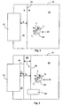
- Figur 4
- eine schematische Darstellung einer Arbeitssituation, an der ein Industrieroboter und eine Person beteiligt sind.
- FIG. 1
- a schematic representation of a device according to the invention on a bending press;
- FIGS. 2 and 3
- the situation shown in Figure 1 in a plan view;
- FIG. 4
- a schematic representation of a work situation in which an industrial robot and a person are involved.
Eine erfindungsgemäße Vorrichtung 10 zum Steuern wenigstens einer
sicherheitsrelevanten Funktion einer Maschine 12, die in den Figuren 1 bis 3 als
eine Gesenkbiegepresse dargestellt ist, weist wenigstens einen orts- und
zeitauflösenden Sensor 14 auf. Der Sensor 14 kann eine Kamera sein oder ein
beliebiger anderer orts- und zeitauflösender Sensor, wie beispielsweise ein
Laserscanner, wie er von der Anmelderin unter der Bezeichnung "PLS" vertrieben
wird. Bei Einsatz von Kameras als Sensoren können zwei Kameras 14 und 16
vorgesehen sein, um eine dreidimensionale Erfassung eines
Überwachungsbereichs 18 zu ermöglichen. An speziellen Gefahrenstellen, wie
beispielsweise im Pressbereich 20 der Maschine 12, könnte wenigstens ein weiterer
Sensor 22 angeordnet sein.A
Im Überwachungsbereich 18 befindet sich ein Objekt 24, das in dem dargestellten
Beispiel eine Bedienperson 26 ist. Die Sensoren 14, 16, 22 sind über
Signalleitungen mit einer Auswerteeinheit 28 verbunden, in der die Sensorsignale
ausgewertet werden können. Die Auswerteeinheit 28 ist über eine geeignete
Verbindung 30 mit der Maschine 12 verbunden, um das Auslösen mindestens einer
sicherheitsrelevanten Funktion steuern zu können. Die sicherheitsrelevante
Funktion kann ein Notstopp der Maschine und/oder nur ein akustisches und/oder
optisches Warnsignal sein. Dazu weist die Maschine 12 oder die Vorrichtung 10
Signal- und/oder Schaltmittel auf, die beispielsweise ein in Fig. 1 schematisch
dargestellter Aus-Schalter 46 und/oder eine Warnleuchte 48 sein können.In the
Weitere Merkmale der erfindungsgemäßen Vorrichtung und die erfindungsgemäßen Verfahren, die mit der Vorrichtung durchführbar sind, sollen im Weiteren an Hand der folgenden Funktionsbeschreibung unter Bezugnahme auf die Figuren 2 und 3 erläutert werden.Further features of the device according to the invention and the invention Procedures that can be carried out with the device should be further on hand the following functional description with reference to Figures 2 and 3 be explained.
In den Figuren 2 und 3 ist der Arbeitsbereich aus Figur 1, bestehend aus Maschine
12 und Überwachungsbereich 18, in einer Draufsicht dargestellt. Die
erfindungsgemäße Vorrichtung 10 mit den Sensoren 14 und 16 und der
Auswerteeinheit 28 ist in dieser Darstellung nicht erkennbar. Die Figuren 2 und 3
zeigen somit ein Bild, wie es der Sensor 14 (bzw. 16) "sieht". Der Sensor 14 (bzw.
16) ist in der Lage, den gesamten Überwachungsbereich 18 zu erfassen, in dem
sich auch die Maschine 12 und die Person 26, befinden. Der Sensor 14 und die
Auswerteeinheit 28 sind mit einer Bilderkennung ausgebildet, um die Person 26 als
ein zu schützendes Objekt erkennen zu können. Wie eine solche Objekterkennung
im Einzelnen funktionieren kann ist aus dem Stand der Technik, wie es
beispielsweise die DE 44 17 128 A1 zeigt, bekannt.In Figures 2 and 3, the work area of Figure 1, consisting of
Der Überwachungsbereich 18 ist durch eine Sicherheitsgrenze 32 in einen
ungefährlichen Bereich 34 und einen durch die Sicherheitsgrenze 32 abgesicherten
Gefahrenbereich 36 aufgeteilt. Wenn die Person 26 die Sicherheitsgrenze 32
überschreitet oder beispielsweise mit dem Arm in den Gefahrenbereich 36
hineinreicht, wird über die Auswerteeinheit 28 eine sicherheitsrelevante Funktion,
beispielsweise ein Notstopp der Maschine 12, über die Signal- und/oder Schaltmittel
46 oder 48 ausgelöst.The
Die Sicherheitsgrenze 32 ist keine physikalisch erkennbare Grenze, sondern wird
über entsprechende Mittel 47 in der Auswerteeinheit 28, beispielsweise
softwaremäßig, festgelegt. Die Mittel 47 zum Festlegen der Sicherheitsgrenze
können in einer programmierbaren Schaltung bestehen. Die Sicherheitsgrenze 32
hat einen Sicherheitsabstand S zur Maschine 12 und definiert die Größe des
Gefahrenbereichs 36. Erfindungsgemäß ist dieser Sicherheitsabstand S, also die
Lage der Sicherheitsgrenze 32, über die Mittel 47 variabel festlegbar in
Abhängigkeit von der Position, der Bewegungsrichtung und/oder der
Bewegungsgeschwindigkeit v der Person 26.The
Die Position, Bewegungsrichtung und/oder Bewegungsgeschwindigkeit v der
Person 26, kann über die Sensoren 14 und 16 und die Auswerteeinheit 28 in an
sich bekannter Weise (siehe z.B. DE 44 17 128 A1) bestimmt werden. Die
Bewegungsgeschwindigkeit v der Person 26, setzt sich zusammen aus einer
Komponente vII parallel zur Maschine 12 und einer Komponente v⊥ senkrecht zur
Maschine 12. Eine Bewegung mit einer ausschließlichen Komponente vII
parallel zur Maschine kann keine Gefahren bewirken. Unter
sicherheitsrelevanten Aspekten ist lediglich die Komponente v⊥, also die effektive
Annäherungsgeschwindigkeit, wichtig. Ist v⊥ groß, so sollte der Sicherheitsabstand
S auch groß sein. Ist v⊥ jedoch klein, d. h. die Person 26 bewegt sich nur langsam
auf die Maschine 12 zu, kann die Sicherheitsgrenze 32 näher an die Maschine 12
gelegt werden. Bevorzugt ist die Geschwindigkeit, mit der die Lage der
Sicherheitsgrenze verschoben wird, einerseits abhängig von der Position der
Person 26 und andererseits von der Geschwindigkeitskomponente v⊥ ist.The position, direction of movement and / or movement speed v of the
An Hand der Darstellung in Figur 3 soll eine weitere Ausführungsform der Erfindung
erläutert werden. Im Unterschied zu dem vorhergehenden Ausführungsbeispiel ist
jetzt nicht eine scharfe Sicherheitsgrenze vorgesehen, sondern ein
Sicherheitsbereich 38 mit einer Ausdehnung A in Richtung senkrecht zur Maschine
12. Auf der einen Seite des Sicherheitsbereichs 38 befindet sich der ungefährliche
Bereich 34 des Überwachungsbereichs 18 und jenseits des Sicherheitsbereichs 38
befindet sich der Gefahrenbereich 36, so dass bei Eindringen in den
Gefahrenbereich 36 ein Übergang der Maschine in einen sicheren Zustand,
beispielsweise in eine langsame Schließbewegung, über die Schaltmittel 46
veranlasst wird.On the basis of the illustration in Figure 3, a further embodiment of the invention
be explained. In contrast to the previous embodiment is
now not a sharp safety limit provided, but a
Tritt die Person 26 lediglich in den Sicherheitsbereich 38 ein, also überschreitet sie
lediglich die gemäß Fig. 3 rechte Grenze 40 des Sicherheitsbereichs 38, kann über
die Signalmittel 48 beispielsweise ein akustisches und/oder optisches Warnsignal
abgegeben werden, das bei Annäherung an die linke Grenze 42 des
Sicherheitsbereichs 38 stärker werden kann. Die sicherheitsrelevante Funktion, die
im Falle der Presse eine langsame Schließbewegung sein kann, ist damit von der
Position, der Bewegungsrichtung und/oder der Bewegungsgeschwindigkeit v der
Person 26 abhängig. Die sichere langsame Bewegung kann beendet werden, wenn
die Person 26 sich zwar noch innerhalb des Sicherheitsbereichs 38 bewegt, jedoch
sich von der Maschine 12 wegbewegt, also den Abstand zur Maschine 12
vergrößert.If the
Abstände S1 und S2 der linken bzw. rechten Grenze 42, 40 des Sicherheitsbereichs
38 von der Maschine 12 können von dem Mittel 47 variabel festgelegt werden. Sie
werden bevorzugt in Abhängigkeit der Position, der Bewegungsrichtung und/oder
der Bewegungsgeschwindigkeit v der Person 26 festgelegt, so dass einerseits die
Ausdehnung A des Sicherheitsbereichs 38 situationsbedingt anpassbar ist und
anderseits auch die Lage des Sicherheitsbereichs 38, also der Abstand zur
Maschine 12, situationsbedingt anpassbar ist.Distances S 1 and S 2 of the left and
Des Weiteren ist in Figur 3 ein Objekt 44 dargestellt, das beispielsweise ein
Materialbeförderungswagen sein könnte. Wenn das Objekt 44 in den
Sicherheitsbereich 38 oder gar in den Gefahrenbereich 34 eindringt, muss die
sicherheitsrelevante Funktion nicht ausgelöst werden, denn von dem Objekt 44
kann keine Gefahr ausgehen, da der Materialbeförderungswagen 44 beispielsweise
niemals in den Pressbereich 20 der Maschine 12 eindringen kann.Furthermore, an
Damit diese Funktion, also ein Nichtauslösen der sicherheitsrelevante Funktion
realisierbar ist, weist die erfindungsgemäße Vorrichtung 10
Objektklassifizierungsmittel 49 auf, die aus einer geeigneten Soft- und Hardware,
die in der Auswerteeinheit 28 integriert ist, bestehen könnten. Durch die
Objektklassifizierungsmittel 49 werden die erkannten Objekte 24 und 44 in Klassen
eingeteilt, so dass die sicherheitsrelevanten Funktionen, wie Warnsignale oder
Notstopps, in Abhängigkeit von der Klasse des in den Sicherheitsbereich 38 bzw.
den Gefahrbereich 36 eindringende Objekte, gesteuert werden können. Objekte wie
der Materialbeförderungswagen 44 werden zu diesem Zweck in eine Klasse von
ungefährdeten Objekten eingruppiert, wohingegen durch die erfindungsgemäße
Vorrichtung erkannte Personen 26 in eine Klasse von gefährdeten Objekten
eingruppiert werden, für die die Sicherheitsgrenze 32 bzw. der Sicherheitsbereich
38 festgelegt werden müssen.So this function, ie a non-triggering the safety-relevant function
can be realized, the
Insgesamt wird durch die Erfindung die Maschinenlaufzeit erhöht und die
Produktionsfläche effektiver genutzt, da einerseits die Ausdehnung des
abgesicherten Gefahrenbereichs 36 situationsbedingt anpassbar ist und nicht jede
Bewegung, die von einer Person oder einem anderen Objekt in der Nähe der
Maschine ausgeführt wird, einen Notstopp der Maschine bewirken muss und
andererseits nicht jedes Eindringen eines Objektes in den Gefahrenbereich 36
einen Notstopp bewirkt. Overall, the machine running time is increased by the invention and the
Used more effectively on the one hand the expansion of the
Die Erfindung ist an den verschiedensten Arten von Maschinen einsetzbar.
Beispielsweise kann es sich bei der Maschine um einen Industrieroboter 50, wie er
in Figur 4 schematisch dargestellt ist, handeln. Mit der erfindungsgemäßen
Vorrichtung kann jetzt ein Schwenkbereich eines Roboterarms 52, die Position des
Roboterarms und die Bewegungsrichtung 56, 58 und Bewegungsgeschwindigkeit
des Roboterarms 52 erfasst werden. Gleichzeitig kann die Position, die
Bewegungsrichtung und Bewegungsgeschwindigkeit einer im Bereich des Roboters
50 arbeitenden Person 54 erkannt werden. Mit der erfindungsgemäßen Vorrichtung
10 kann die Tätigkeit des Roboters in sicherheitsrelevanten Aspekten gesteuert
werden, so dass dadurch sichergestellt ist, dass die sich Roboter 50 und Person 54
sich nie treffen und die in der Nähe des Roboterarms 52 befindende Person 54
niemals verletzt wird. Dabei muss der Roboter 50 nicht großräumig durch eine
Sperrzone gesichert sein, sondern über die erfindungsgemäße Vorrichtung 10 kann
der Schutzbereich um den Roboterarm 52 herum situationsangepasst variabel
festgelegt werden und mit dem Roboterarm 52 "mitwandern". Damit ist ein
verbessertes Arbeiten im Bereich eines Industrieroboters oder sogar eine
gefahrlose Zusammenarbeit zwischen dem Roboter 50 und der Person 54 möglich.The invention can be used on a wide variety of types of machines.
For example, the machine may be an
An diesem Beispiel wird deutlich, dass auch die Form der Sicherheitsgrenze bzw. des Sicherheitsbereichs den Maschinen, wie Gesenkbiegepresse oder Industrieroboter, angepasst ausgeführt sein kann.This example makes it clear that the shape of the safety limit or the safety area of the machines, such as press brake or Industrial robot, adapted to be executed.
Claims (11)
- Method of controlling at least one safety-specific function of a machine (12), in the case of which a monitoring region (18) is monitored by at least one location- and time-resolving sensor (14, 16, 22) and a position, a movement direction and/or a movement speed (v) of an object (24, 26) are detected and the monitoring region (18) comprises a safety boundary (32), which separates off a danger region (36) and defines a safe distance (S) from a danger zone of the machine (12), and penetration into the danger region (36) triggers the safety-specific function and the position of the safety boundary (32) can be established in a variable manner in dependence on the position, the movement direction and/or movement speed (v).
- Method according to Claim 1, characterized in that a speed at which the position of the safety boundary (32) is displaced is dependent on the position, the movement direction and/or the movement speed (v) of the object (24, 26).
- Method of controlling at least one safety-specific function of the machine (12), in particular according to one of the preceding claims, in the case of which a monitoring region (18) is monitored by at least one location- and time-resolving sensor (14, 16, 22) and a position, a movement direction and/or a movement speed (v) of an object (24, 26) are detected and the monitoring region (18) comprises a safety region (38), which separates off a danger region (36), and penetration into the danger region (36) triggers the safety-specific function and an extent (A) of the safety-boundary region (38) is established in a variable manner in dependence on the position, the movement direction and/or movement speed (v) of the object (24, 26).
- Method according to one of the preceding claims, characterized in that the object (24, 26, 44) is classified by an object-classifying means (46).
- Method according to Claim 4, characterized in that the safety-specific function of the machine is controlled in dependence on the class of the object (26, 44).
- Method according to one of the preceding claims, characterized in that the safety-specific function of the machine is controlled in dependence on the position, the movement direction and/or the movement speed (v) of the object (26).
- Apparatus for controlling at least one safety-specific function of a machine (12), having a monitoring region (18) in which an object (24, 26) can be monitored by at least one location- and time-resolving sensor (14, 16, 22), having an evaluating unit (28) for determining the position, movement direction and/or movement speed (v) of the object (26) from the sensor signals, having means (47) for establishing a safety boundary (32), which separates off a danger region (36) and defines a safe distance (S) from the machine (12), it being possible for the position of the safety boundary (32) in the monitoring region (18) to be established in dependence on the position, the movement direction and/or the movement speed (v) of the object (26), and having signalling and/or switching means (46, 48) for triggering the safety-specific function following penetration into the danger region (36).
- Apparatus for controlling at least one safety-specific function of a machine (12) in particular according to Claim 7, having a monitoring region (18) in which an object (26) can be monitored by at least one location- and time-resolving sensor (14, 16, 22), having an evaluating unit (28) for determining the position, movement direction and/or movement speed (v) of the object (26) from the sensor signals, having means (47) for establishing the extent of a safety region (38), which separates off a danger region (36), in the monitoring region (18), it being possible for an extent (A) of the safety region (38) to be established in a variable manner in dependence on the position, the movement direction and/or the movement speed (v) of the object (26), and having signalling and/or switching means (46, 48) for triggering the safety-specific function following penetration into the danger region (36).
- Apparatus according to one of the preceding Claims 7 or 8, characterized in that the safety-specific function of the machine (12) can be controlled in dependence on the position, the movement direction and/or the movement speed (v) of the object (26).
- Apparatus according to one of the preceding Claims 7 to 9, characterized in that at least one object-classifying means (46) is provided for classifying the object (26, 44).
- Apparatus according to Claim 10, characterized in that the safety-specific function of the machine can be controlled in dependence on the class of the object (26, 44).
Applications Claiming Priority (2)
| Application Number | Priority Date | Filing Date | Title |
|---|---|---|---|
| DE10152543A DE10152543A1 (en) | 2001-10-24 | 2001-10-24 | Method and device for controlling a safety-relevant function of a machine |
| DE10152543 | 2001-10-24 |
Publications (4)
| Publication Number | Publication Date |
|---|---|
| EP1306603A2 EP1306603A2 (en) | 2003-05-02 |
| EP1306603A3 EP1306603A3 (en) | 2004-03-31 |
| EP1306603B1 true EP1306603B1 (en) | 2005-03-02 |
| EP1306603B2 EP1306603B2 (en) | 2011-06-29 |
Family
ID=7703604
Family Applications (1)
| Application Number | Title | Priority Date | Filing Date |
|---|---|---|---|
| EP02021518A Expired - Lifetime EP1306603B2 (en) | 2001-10-24 | 2002-09-26 | Process and device for controlling a safety-relevant function of a machine |
Country Status (5)
| Country | Link |
|---|---|
| US (1) | US6778092B2 (en) |
| EP (1) | EP1306603B2 (en) |
| JP (1) | JP2003222295A (en) |
| AT (1) | ATE290186T1 (en) |
| DE (2) | DE10152543A1 (en) |
Cited By (2)
| Publication number | Priority date | Publication date | Assignee | Title |
|---|---|---|---|---|
| EP3524870B1 (en) | 2018-02-08 | 2020-11-04 | Omron Europe B.V. | Monitoring device and method for monitoring a monitored zone |
| EP3916286A1 (en) | 2020-05-29 | 2021-12-01 | Sick Ag | Optoelectronic safety sensor and method for securing a machine |
Families Citing this family (140)
| Publication number | Priority date | Publication date | Assignee | Title |
|---|---|---|---|---|
| JP3716803B2 (en) * | 2002-03-07 | 2005-11-16 | オムロン株式会社 | Risk assessment support device and program product |
| JP4511345B2 (en) * | 2002-06-11 | 2010-07-28 | デイビス,ケヴィン,ステファン | Safety system |
| EP1535706A1 (en) * | 2002-07-18 | 2005-06-01 | Kabushiki Kaisha Yaskawa Denki | Robot controller and robot system |
| JP4066168B2 (en) * | 2003-03-13 | 2008-03-26 | オムロン株式会社 | Intruder monitoring device |
| DE10324517A1 (en) * | 2003-05-28 | 2004-12-16 | Daimlerchrysler Ag | Robot and teaching method therefor, for controlling the area in which the robot operates, is based on definition of permitted and forbidden movement areas in a computer model defining the robot's range of movement |
| DE10324628A1 (en) * | 2003-05-28 | 2004-12-16 | Daimlerchrysler Ag | Control method for robot especially fixed mounted robots, involves verifying whether or not each object in monitoring zone has scheduled intrusion into working program |
| DE10360789B4 (en) * | 2003-12-23 | 2007-03-15 | Leuze Lumiflex Gmbh + Co. Kg | Device for monitoring a detection area on a work equipment |
| DE102004020024A1 (en) * | 2004-04-23 | 2005-11-10 | Sick Ag | Method for securing a machine tool and optoelectronic sensor for carrying out such a method |
| US8210791B2 (en) | 2004-05-03 | 2012-07-03 | Jervis B. Webb Company | Automatic transport loading system and method |
| AU2005240554B2 (en) * | 2004-05-03 | 2010-09-23 | Jervis B. Webb International Company | Automatic transport loading system and method |
| US7980808B2 (en) * | 2004-05-03 | 2011-07-19 | Jervis B. Webb Company | Automatic transport loading system and method |
| US8075243B2 (en) | 2004-05-03 | 2011-12-13 | Jervis B. Webb Company | Automatic transport loading system and method |
| US8192137B2 (en) | 2004-05-03 | 2012-06-05 | Jervis B. Webb Company | Automatic transport loading system and method |
| JP2005324297A (en) * | 2004-05-17 | 2005-11-24 | Matsushita Electric Ind Co Ltd | Robot |
| DE102004041821A1 (en) | 2004-08-27 | 2006-03-16 | Abb Research Ltd. | Device and method for securing a machine-controlled handling device |
| DE102004043515A1 (en) * | 2004-09-08 | 2006-03-09 | Sick Ag | Method and device for detecting an object |
| DE102004043514A1 (en) * | 2004-09-08 | 2006-03-09 | Sick Ag | Method and device for controlling a safety-related function of a machine |
| US8132225B2 (en) * | 2004-09-30 | 2012-03-06 | Rockwell Automation Technologies, Inc. | Scalable and flexible information security for industrial automation |
| DE102004048563A1 (en) * | 2004-10-04 | 2006-04-13 | Benteler Automobiltechnik Gmbh | Monitoring system for an industrial robot prevents collision with objects within field of operation |
| CN100556623C (en) * | 2004-10-19 | 2009-11-04 | 松下电器产业株式会社 | Robot apparatus |
| DE102004055229A1 (en) * | 2004-11-17 | 2006-05-18 | Heidelberger Druckmaschinen Ag | Dangerous zone e.g. sheet feeder, securing method for printing machine, involves affecting object based on operating condition of machine and identification of object in zone by sensor that differentiates human body part and article |
| DE102005006557A1 (en) * | 2005-02-11 | 2006-08-31 | Zf Friedrichshafen Ag | Bump stop for a door or flap of a motor vehicle |
| DE102005011143A1 (en) * | 2005-03-10 | 2006-09-14 | Sick Ag | Device for controlling safety relevant function of robot or machine tool has means to change contour of safety area depending on displacement, position and operational data and on transmitted control data of robot or machine tool |
| US7328871B2 (en) * | 2005-04-14 | 2008-02-12 | Progressive Rail Technologies, Inc. | Railroad car coupler gap analyzer |
| FR2884591B1 (en) * | 2005-04-15 | 2010-10-08 | Goss Int Montataire Sa | SECURITY SYSTEM AND CORRESPONDING PRESS |
| US7708232B2 (en) * | 2005-05-19 | 2010-05-04 | Progressive Rail Technologies, Inc. | Railroad car lateral instability and tracking error detector |
| JP4764070B2 (en) * | 2005-05-24 | 2011-08-31 | 本田技研工業株式会社 | Work station safety system |
| US20060276958A1 (en) * | 2005-06-02 | 2006-12-07 | Jervis B. Webb Company | Inertial navigational guidance system for a driverless vehicle utilizing laser obstacle sensors |
| EP1790474A1 (en) * | 2005-11-28 | 2007-05-30 | Kba-Giori S.A. | Sheet-fed or web-fed printing machine |
| WO2007067898A2 (en) * | 2005-12-05 | 2007-06-14 | Global Precision Solutions, Llp. | Distance correction for damage prevention system |
| FR2894318B1 (en) * | 2005-12-07 | 2008-03-07 | Lectra Sa | ACTIVE SECURITY MANAGEMENT METHOD FOR AN AUTOMATIC WORKING MACHINE. |
| DE602006003058D1 (en) * | 2006-02-17 | 2008-11-20 | Abb Research Ltd | Robotic System |
| DE102006012823B4 (en) | 2006-03-21 | 2016-12-22 | Leuze Electronic Gmbh + Co. Kg | Device for monitoring a danger zone on a work equipment |
| JP5035768B2 (en) * | 2006-04-18 | 2012-09-26 | 独立行政法人産業技術総合研究所 | Safety device for human robot coexistence work |
| US20070279525A1 (en) * | 2006-06-01 | 2007-12-06 | Kuohua Wu | Audience detection for increasing component longevity |
| DE102006048163B4 (en) * | 2006-07-31 | 2013-06-06 | Pilz Gmbh & Co. Kg | Camera-based monitoring of moving machines and / or moving machine elements for collision prevention |
| DE102006046759B4 (en) * | 2006-09-29 | 2018-05-17 | Abb Ag | Method for increasing the safety during operation of a robot |
| DE102007006708A1 (en) | 2007-02-10 | 2008-08-14 | Abb Research Ltd. | Method for securing a handling device |
| DE102007013299A1 (en) | 2007-03-06 | 2008-09-11 | Cedes Ag | Sensor device and system with a conveyor and a sensor device |
| JP5377837B2 (en) * | 2007-05-31 | 2013-12-25 | 株式会社キーエンス | Photoelectric sensor |
| DE102007028390A1 (en) * | 2007-06-15 | 2008-12-18 | Abb Research Ltd. | Process control, system and method for the automated adaptation of process parameters of at least one handling device |
| JP2009050958A (en) * | 2007-08-27 | 2009-03-12 | Fanuc Ltd | Apparatus for controlling robot having stop monitoring function |
| JP4986154B2 (en) * | 2007-10-05 | 2012-07-25 | 独立行政法人産業技術総合研究所 | Robot, robot controller, robot control program, simulator for creating robot control program |
| DE102007048684B4 (en) * | 2007-10-10 | 2010-09-09 | Polysius Ag | laboratory system |
| JP5190761B2 (en) * | 2008-01-10 | 2013-04-24 | 株式会社Ihi | MOBILE ROBOT MONITORING DEVICE AND MONITORING METHOD |
| EP2083209B1 (en) * | 2008-01-28 | 2012-10-17 | Sick Ag | Security system for contactless measurement of paths and/or speeds |
| EP2093725B1 (en) | 2008-02-20 | 2011-12-14 | Sick Ag | Monitoring with a sensor element |
| DE102008013431A1 (en) * | 2008-03-10 | 2009-05-07 | Siemens Aktiengesellschaft | Machine safety-oriented stopping procedure, involves releasing turn-off impulse in case of endangerment to persons, and stopping machine within maximum deceleration time during operation of machine |
| US8990098B2 (en) | 2008-04-30 | 2015-03-24 | Ecolab Inc. | Validated healthcare cleaning and sanitizing practices |
| US8639527B2 (en) | 2008-04-30 | 2014-01-28 | Ecolab Usa Inc. | Validated healthcare cleaning and sanitizing practices |
| DE102009051145A1 (en) | 2008-10-29 | 2010-05-06 | Sms Siemag Aktiengesellschaft | Robotized metallurgical plant |
| JP2010120139A (en) * | 2008-11-21 | 2010-06-03 | New Industry Research Organization | Safety control device for industrial robot |
| WO2010060475A1 (en) * | 2008-11-26 | 2010-06-03 | Abb Research Ltd. | Industrial robot |
| DE202008016093U1 (en) * | 2008-12-05 | 2010-04-15 | Sick Ag | monitoring sensor |
| DE102009010460B4 (en) * | 2009-02-13 | 2010-11-25 | Pilz Gmbh & Co. Kg | Device and method for determining the follow-up time of a machine |
| JP5343641B2 (en) * | 2009-03-12 | 2013-11-13 | 株式会社Ihi | Robot apparatus control device and robot apparatus control method |
| JP5229902B2 (en) * | 2009-03-30 | 2013-07-03 | 独立行政法人産業技術総合研究所 | Safe position detector with intrusion detection function |
| DE202009006683U1 (en) * | 2009-05-08 | 2010-09-30 | Sick Ag | Access protection system |
| USRE48951E1 (en) | 2015-08-05 | 2022-03-01 | Ecolab Usa Inc. | Hand hygiene compliance monitoring |
| EP2441063B1 (en) | 2009-06-12 | 2015-03-11 | Ecolab USA Inc. | Hand hygiene compliance monitoring |
| DE102009034848B4 (en) | 2009-07-27 | 2014-02-20 | Sick Ag | Optoelectronic sensor |
| US20110168037A1 (en) * | 2010-01-11 | 2011-07-14 | The Texas A&M University System | Autonomous module builder |
| EP2386876B1 (en) | 2010-05-04 | 2013-07-10 | Sick AG | Optoelectronic safety sensor for measuring distance and method for monitoring a surveillance area |
| EP2569762A4 (en) * | 2010-05-12 | 2015-05-20 | Proxisafe Ltd | Event warning system and method thereof |
| US20110298579A1 (en) * | 2010-06-08 | 2011-12-08 | Cedes Safety & Automation Ag | Dynamically adaptable safety zones |
| EP2395372B1 (en) * | 2010-06-09 | 2013-10-09 | Sick AG | Safety scanner |
| US8781629B2 (en) | 2010-09-22 | 2014-07-15 | Toyota Motor Engineering & Manufacturing North America, Inc. | Human-robot interface apparatuses and methods of controlling robots |
| US20120095575A1 (en) * | 2010-10-14 | 2012-04-19 | Cedes Safety & Automation Ag | Time of flight (tof) human machine interface (hmi) |
| DE102010050547A1 (en) | 2010-11-05 | 2012-05-10 | Kuka Laboratories Gmbh | Method and device for safety monitoring of a robot |
| DE102010063125A1 (en) * | 2010-12-15 | 2012-06-21 | Robert Bosch Gmbh | Method for inductive transmission of electrical energy to energy storage device of vehicle, involves interrupting transmission of energy when distance between transmission unit and radiation-sensitive component is below preset distance |
| DE102010063214A1 (en) * | 2010-12-16 | 2012-06-21 | Robert Bosch Gmbh | Securing device for a handling device, in particular an industrial robot, and method for operating the securing device |
| WO2012098609A1 (en) | 2011-01-17 | 2012-07-26 | パナソニック株式会社 | Safety device and preliminary action determination method |
| US20140210620A1 (en) | 2013-01-25 | 2014-07-31 | Ultraclenz Llc | Wireless communication for dispenser beacons |
| CN102810239A (en) * | 2011-05-31 | 2012-12-05 | 鸿富锦精密工业(深圳)有限公司 | Accident prevention system and method |
| JP5378479B2 (en) * | 2011-10-31 | 2013-12-25 | 株式会社キーエンス | Photoelectric sensor and setting method thereof |
| CN103192414B (en) * | 2012-01-06 | 2015-06-03 | 沈阳新松机器人自动化股份有限公司 | Robot anti-collision protection device and method based on machine vision |
| DE102012007242A1 (en) * | 2012-03-09 | 2013-09-12 | Fraunhofer-Gesellschaft zur Förderung der angewandten Forschung e.V. | Monitoring system for ensuring cooperation between worker and robot in human robot cooperation system, has control unit that controls robot using position of worker and region crossed by worker and robot in and/or from danger area |
| JP5970880B2 (en) * | 2012-03-15 | 2016-08-17 | オムロン株式会社 | Power source control device |
| DE102012102236A1 (en) | 2012-03-16 | 2013-09-19 | Pilz Gmbh & Co. Kg | Method and device for securing a hazardous working area of an automated machine |
| JP5924134B2 (en) * | 2012-05-30 | 2016-05-25 | セイコーエプソン株式会社 | Intrusion detection device, robot system, intrusion detection method, and intrusion detection program |
| JP5965214B2 (en) * | 2012-05-31 | 2016-08-03 | 株式会社アマダホールディングス | Bending device operation control method and operation control system, and bending work training system and training method |
| JP5549724B2 (en) * | 2012-11-12 | 2014-07-16 | 株式会社安川電機 | Robot system |
| JP6123307B2 (en) | 2013-01-23 | 2017-05-10 | 株式会社デンソーウェーブ | Surveillance system and method for monitoring the intrusion of an object around a robot |
| JP5668770B2 (en) * | 2013-03-15 | 2015-02-12 | 株式会社安川電機 | Robot system and control method of robot system |
| DE102013104265A1 (en) * | 2013-04-26 | 2014-10-30 | Pilz Gmbh & Co. Kg | Device and method for securing an automated machine |
| JP6122343B2 (en) * | 2013-06-03 | 2017-04-26 | 株式会社アマダホールディングス | Simulation system and method |
| DE102013106514B3 (en) * | 2013-06-21 | 2014-10-30 | Pilz Gmbh & Co. Kg | Device and method for securing an automated machine |
| DE202013104264U1 (en) * | 2013-09-18 | 2015-01-09 | Daimler Ag | workstation |
| DE102013110901B4 (en) | 2013-10-01 | 2022-11-10 | Mercedes-Benz Group AG | HRC planning technology |
| DE102013110905A1 (en) * | 2013-10-01 | 2015-04-02 | Daimler Ag | MRK planning and monitoring technology |
| TWI547355B (en) * | 2013-11-11 | 2016-09-01 | 財團法人工業技術研究院 | Safety monitoring system of human-machine symbiosis and method using the same |
| DE202014100411U1 (en) * | 2014-01-30 | 2015-05-05 | Kuka Systems Gmbh | safety device |
| TWI592265B (en) * | 2014-06-25 | 2017-07-21 | Hiwin Tech Corp | Safety control method of mechanical arm |
| DE102014226691A1 (en) | 2014-12-19 | 2016-06-23 | Carl Zeiss Industrielle Messtechnik Gmbh | Method for monitoring a coordinate measuring machine |
| JP6034892B2 (en) | 2015-01-27 | 2016-11-30 | ファナック株式会社 | A robot system in which the brightness of the robot mount changes |
| CN104723350B (en) * | 2015-03-16 | 2016-07-20 | 珠海格力电器股份有限公司 | Industrial robot safety intelligent control method and system |
| US10834065B1 (en) | 2015-03-31 | 2020-11-10 | F5 Networks, Inc. | Methods for SSL protected NTLM re-authentication and devices thereof |
| JP6481495B2 (en) * | 2015-05-08 | 2019-03-13 | 株式会社デンソーウェーブ | Robot safety device |
| DE102015007395A1 (en) * | 2015-06-08 | 2016-12-08 | Kuka Roboter Gmbh | Method and system for operating and / or monitoring a machine, in particular a robot |
| JP6177837B2 (en) * | 2015-06-30 | 2017-08-09 | ファナック株式会社 | Robot system using visual sensor |
| US10198706B2 (en) * | 2015-07-31 | 2019-02-05 | Locus Robotics Corp. | Operator identification and performance tracking |
| JP6088605B1 (en) * | 2015-08-31 | 2017-03-01 | ファナック株式会社 | Robot system using visual sensor |
| JP6601155B2 (en) * | 2015-10-28 | 2019-11-06 | 株式会社デンソーウェーブ | Robot control system |
| DE102015225587A1 (en) * | 2015-12-17 | 2017-06-22 | Volkswagen Aktiengesellschaft | Interaction system and method for interaction between a person and at least one robot unit |
| US10404698B1 (en) | 2016-01-15 | 2019-09-03 | F5 Networks, Inc. | Methods for adaptive organization of web application access points in webtops and devices thereof |
| DE102016200455A1 (en) * | 2016-01-15 | 2017-07-20 | Fraunhofer-Gesellschaft zur Förderung der angewandten Forschung e.V. | Safety device and method for safe operation of a robot |
| DE102016007520A1 (en) * | 2016-06-20 | 2017-12-21 | Kuka Roboter Gmbh | Monitoring a robot arrangement |
| DE102016007519A1 (en) * | 2016-06-20 | 2017-12-21 | Kuka Roboter Gmbh | Monitoring a system with at least one robot |
| US11000953B2 (en) * | 2016-08-17 | 2021-05-11 | Locus Robotics Corp. | Robot gamification for improvement of operator performance |
| DE102016222245A1 (en) * | 2016-11-14 | 2018-05-30 | Volkswagen Aktiengesellschaft | Device and method for acting on objects |
| JP6490121B2 (en) * | 2017-02-17 | 2019-03-27 | ファナック株式会社 | Robot system |
| EP3965084A1 (en) | 2017-03-07 | 2022-03-09 | Ecolab USA Inc. | Monitoring modules for hand hygiene dispensers |
| JP2018192556A (en) * | 2017-05-16 | 2018-12-06 | オムロン株式会社 | Robot system |
| JP6416980B1 (en) * | 2017-05-17 | 2018-10-31 | ファナック株式会社 | Monitoring device for monitoring a spatial area obtained by dividing a monitoring area |
| DE102017005604A1 (en) * | 2017-06-12 | 2018-12-13 | Kuka Deutschland Gmbh | Monitoring a robot |
| EP3421189B1 (en) * | 2017-06-28 | 2019-05-22 | Sick AG | Method for monitoring a machine |
| DE102017213658A1 (en) * | 2017-08-07 | 2019-02-07 | Robert Bosch Gmbh | Handling arrangement with a handling device for performing at least one work step and method and computer program |
| JP6680730B2 (en) * | 2017-08-08 | 2020-04-15 | ファナック株式会社 | Control device and learning device |
| JP2019058990A (en) * | 2017-09-27 | 2019-04-18 | ファナック株式会社 | Robot system |
| DE102017123295A1 (en) * | 2017-10-06 | 2019-04-11 | Pilz Gmbh & Co. Kg | Security system to ensure the cooperative operation of people, robots and machines |
| US10529219B2 (en) | 2017-11-10 | 2020-01-07 | Ecolab Usa Inc. | Hand hygiene compliance monitoring |
| DE102017127184A1 (en) | 2017-11-17 | 2019-05-23 | Liebherr-Verzahntechnik Gmbh | Workpiece-lock |
| ES1222444Y (en) * | 2017-12-06 | 2019-03-22 | Wide Automation S R L | Security system |
| JP6748145B2 (en) | 2018-05-15 | 2020-08-26 | ファナック株式会社 | Robot system |
| EP3572971B1 (en) * | 2018-05-22 | 2021-02-24 | Sick Ag | Securing a surveillance area with at least one machine |
| US10438464B1 (en) | 2018-06-06 | 2019-10-08 | Ademco Inc. | Systems and methods for determining and verifying a presence of an object or an intruder in a secured area |
| DE202018105474U1 (en) * | 2018-09-24 | 2020-01-03 | Leuze Electronic Gmbh + Co. Kg | Device for protecting a hazardous area of a plant |
| US11074794B2 (en) | 2018-11-30 | 2021-07-27 | Ademco Inc. | Systems and methods for activating and deactivating controlled devices in a secured area |
| US10996325B2 (en) | 2018-11-30 | 2021-05-04 | Ademco Inc. | Systems and methods for adjusting a signal broadcast pattern of an intrusion detector |
| CN113424233B (en) * | 2018-12-20 | 2023-07-28 | 西克股份公司 | Sensor device for detecting a target object influenced by or formed during a process |
| EP3900307A1 (en) | 2018-12-20 | 2021-10-27 | Ecolab USA, Inc. | Adaptive route, bi-directional network communication |
| AT522116A1 (en) * | 2019-01-22 | 2020-08-15 | Engel Austria Gmbh | Procedures for customizing security areas |
| JP7036078B2 (en) | 2019-03-28 | 2022-03-15 | オムロン株式会社 | Control system, control method, and control unit |
| JP7226101B2 (en) * | 2019-05-28 | 2023-02-21 | オムロン株式会社 | SAFETY MONITORING SYSTEM, SAFETY MONITORING CONTROL DEVICE, AND SAFETY MONITORING METHOD |
| US10762773B1 (en) | 2019-08-19 | 2020-09-01 | Ademco Inc. | Systems and methods for building and using a false alarm predicting model to determine whether to alert a user and/or relevant authorities about an alarm signal from a security system |
| KR20210039635A (en) * | 2019-10-02 | 2021-04-12 | 엘지전자 주식회사 | Robot system and control method of the same |
| IT201900021108A1 (en) * | 2019-11-13 | 2021-05-13 | Gamma System S R L | Safety system for an industrial machinery |
| CN111055297B (en) * | 2020-01-14 | 2023-06-06 | 腾讯科技(深圳)有限公司 | Manipulator operation device, control method, control device, computer device and medium |
| DE102020103597A1 (en) | 2020-02-12 | 2021-08-12 | Saf-Holland Gmbh | Method and system for determining an orientation of a trailer with respect to a towing vehicle |
| DE202022103234U1 (en) * | 2022-06-08 | 2023-09-20 | Leuze Electronic Gmbh + Co. Kg | Monitoring facility |
Family Cites Families (18)
| Publication number | Priority date | Publication date | Assignee | Title |
|---|---|---|---|---|
| EP0179252A3 (en) * | 1984-09-14 | 1987-07-15 | Siemens Aktiengesellschaft | Method and apparatus for protecting people in the operating range of a movable part of a traversing or swiveling machine, particularly of an industrial robot |
| DE3700009A1 (en) * | 1987-01-02 | 1988-07-14 | Mel Mikroelektronik Gmbh | Optoelectronic protection zone device |
| US4918560A (en) * | 1988-07-29 | 1990-04-17 | Harvard Ind Inc | Proximity operated machine control |
| DE3932665A1 (en) * | 1989-09-29 | 1991-04-11 | Rieter Ag Maschf | MONITORING DEVICE |
| US5047752A (en) * | 1989-11-14 | 1991-09-10 | Murata Wiedemann, Inc. | Safety system for a machine tool |
| US5280622A (en) * | 1992-07-17 | 1994-01-18 | Mitsubishi Semiconductor America, Inc. | Combined light beam and ultrasonic transducer safety sensing system |
| DE4405376C1 (en) † | 1994-02-19 | 1995-02-16 | Leuze Electronic Gmbh & Co | Method for detecting objects in a monitoring area |
| DE4417128A1 (en) * | 1994-05-16 | 1995-12-14 | Elnic Gmbh | Closed-circuit video surveillance system with image processing |
| AUPN744696A0 (en) * | 1996-01-05 | 1996-02-01 | Appleyard, Thomas John | Safety apparatus and protection method for machines |
| DE19601661C1 (en) † | 1996-01-18 | 1997-07-17 | Leuze Electronic Gmbh & Co | Object detection method for surveillance system |
| US6108071A (en) * | 1997-12-12 | 2000-08-22 | Laser Atlanta | Speed and position measurement system |
| DE19809210A1 (en) * | 1998-03-04 | 1999-09-16 | Siemens Ag | Locality or workplace surveillance method |
| DE19917509C1 (en) * | 1999-04-17 | 2000-05-25 | Leuze Electronic Gmbh & Co | Optoelectronic device for detecting objects in a monitored area; has dimensions of monitored areas stored in evaluation unit for activation by one of several switches connected to inputs |
| AUPQ022199A0 (en) * | 1999-05-05 | 1999-06-03 | Lazer Safe Pty Ltd | Industrial press safety system |
| DE19938639B4 (en) * | 1999-08-14 | 2006-08-24 | Pilz Gmbh & Co. Kg | Device for securing a danger zone, in particular the danger zone of an automated machine |
| US6297844B1 (en) | 1999-11-24 | 2001-10-02 | Cognex Corporation | Video safety curtain |
| DE29920715U1 (en) † | 1999-11-25 | 2000-02-24 | Leuze Lumiflex Gmbh & Co | Photoelectric switch arrangement for monitoring a danger zone of a machine |
| DE10000287B4 (en) | 2000-01-07 | 2004-02-12 | Leuze Lumiflex Gmbh + Co. Kg | Device and method for monitoring a detection area on a work equipment |
-
2001
- 2001-10-24 DE DE10152543A patent/DE10152543A1/en not_active Withdrawn
-
2002
- 2002-09-26 AT AT02021518T patent/ATE290186T1/en not_active IP Right Cessation
- 2002-09-26 EP EP02021518A patent/EP1306603B2/en not_active Expired - Lifetime
- 2002-09-26 DE DE50202365T patent/DE50202365D1/en not_active Expired - Lifetime
- 2002-10-18 JP JP2002304506A patent/JP2003222295A/en active Pending
- 2002-10-24 US US10/279,075 patent/US6778092B2/en not_active Expired - Lifetime
Cited By (4)
| Publication number | Priority date | Publication date | Assignee | Title |
|---|---|---|---|---|
| EP3524870B1 (en) | 2018-02-08 | 2020-11-04 | Omron Europe B.V. | Monitoring device and method for monitoring a monitored zone |
| EP3524870B2 (en) † | 2018-02-08 | 2023-08-02 | Omron Europe B.V. | Monitoring device and method for monitoring a monitored zone |
| EP3916286A1 (en) | 2020-05-29 | 2021-12-01 | Sick Ag | Optoelectronic safety sensor and method for securing a machine |
| DE102020114488B3 (en) | 2020-05-29 | 2021-12-02 | Sick Ag | Optoelectronic safety sensor and method for protecting a machine |
Also Published As
| Publication number | Publication date |
|---|---|
| US20030076224A1 (en) | 2003-04-24 |
| EP1306603A2 (en) | 2003-05-02 |
| US6778092B2 (en) | 2004-08-17 |
| JP2003222295A (en) | 2003-08-08 |
| ATE290186T1 (en) | 2005-03-15 |
| DE50202365D1 (en) | 2005-04-07 |
| EP1306603A3 (en) | 2004-03-31 |
| DE10152543A1 (en) | 2003-05-08 |
| EP1306603B2 (en) | 2011-06-29 |
Similar Documents
| Publication | Publication Date | Title |
|---|---|---|
| EP1306603B1 (en) | Process and device for controlling a safety-relevant function of a machine | |
| EP1662349B1 (en) | Safeguarding of machines dependent on the status of the machines | |
| EP1635107B2 (en) | Method and apparatus for the control of a machine safety function | |
| EP1418380B1 (en) | Method and device for monitoring an area | |
| EP1662195B1 (en) | Safety device and method for determining the overrun of a machine | |
| EP1918629B1 (en) | Machining unit | |
| DE10143505B4 (en) | Safety procedure and optoelectronic sensor | |
| DE102012007242A1 (en) | Monitoring system for ensuring cooperation between worker and robot in human robot cooperation system, has control unit that controls robot using position of worker and region crossed by worker and robot in and/or from danger area | |
| DE102005050824A1 (en) | Dangerous area protecting method for use in sheet rotation printing machine, involves monitoring dangerous area by sensor, detecting position of object penetrating cross section and activating machine based on detected position | |
| DE202015004517U1 (en) | machine tool | |
| EP1522784B1 (en) | Device with safety system | |
| EP1748245A2 (en) | Protective device for machines such as bending presses, cutting machines, punching machines or the like | |
| EP2177402A1 (en) | Method for detecting deformations in a vehicle component and corresponding motor vehicle | |
| WO1998047645A1 (en) | Machine | |
| DE202021100243U1 (en) | Format circular saw with safety device to avoid cut injuries | |
| AT520726B1 (en) | Method for monitoring a production plant and manufacturing plant with a security system | |
| DE102008033195B4 (en) | Machining center with a workpiece transport device and a workpiece supply station with opto-electronic protective device | |
| DE10353353A1 (en) | Safety method and safety device for a machine, in particular a bending press | |
| DE102017119275B4 (en) | light curtain | |
| DE202008003444U1 (en) | Safety device for securing a machine | |
| DE202005003596U1 (en) | Monitoring unit for an access prevention area of dangerous equipment has a control unit with a control output for activating a mechanical separating arrangement and a switching output for turning the dangerous equipment off | |
| DE202014105201U1 (en) | Switch and safety system for monitoring a permissible working operation of a machine or a device | |
| EP1693686A1 (en) | Optoelectronic sensor | |
| DE10163537A1 (en) | Non-contact protective device | |
| DE202004019536U1 (en) | Safety system for machine tools or robots comprises IR beam system which produces alarm if object enters outer area, light grid system shutting machine down if object is detected in inner area |
Legal Events
| Date | Code | Title | Description |
|---|---|---|---|
| PUAI | Public reference made under article 153(3) epc to a published international application that has entered the european phase |
Free format text: ORIGINAL CODE: 0009012 |
|
| AK | Designated contracting states |
Designated state(s): AT BE BG CH CY CZ DE DK EE ES FI FR GB GR IE IT LI LU MC NL PT SE SK TR |
|
| AX | Request for extension of the european patent |
Extension state: AL LT LV MK RO SI |
|
| PUAL | Search report despatched |
Free format text: ORIGINAL CODE: 0009013 |
|
| AK | Designated contracting states |
Kind code of ref document: A3 Designated state(s): AT BE BG CH CY CZ DE DK EE ES FI FR GB GR IE IT LI LU MC NL PT SE SK TR |
|
| AX | Request for extension of the european patent |
Extension state: AL LT LV MK RO SI |
|
| GRAP | Despatch of communication of intention to grant a patent |
Free format text: ORIGINAL CODE: EPIDOSNIGR1 |
|
| 17P | Request for examination filed |
Effective date: 20040507 |
|
| GRAS | Grant fee paid |
Free format text: ORIGINAL CODE: EPIDOSNIGR3 |
|
| AKX | Designation fees paid |
Designated state(s): AT BE BG CH CY CZ DE DK EE ES FI FR GB GR IE IT LI LU MC NL PT SE SK TR |
|
| GRAA | (expected) grant |
Free format text: ORIGINAL CODE: 0009210 |
|
| AK | Designated contracting states |
Kind code of ref document: B1 Designated state(s): AT BE BG CH CY CZ DE DK EE ES FI FR GB GR IE IT LI LU MC NL PT SE SK TR |
|
| PG25 | Lapsed in a contracting state [announced via postgrant information from national office to epo] |
Ref country code: EE Free format text: LAPSE BECAUSE OF FAILURE TO SUBMIT A TRANSLATION OF THE DESCRIPTION OR TO PAY THE FEE WITHIN THE PRESCRIBED TIME-LIMIT Effective date: 20050302 Ref country code: IE Free format text: LAPSE BECAUSE OF FAILURE TO SUBMIT A TRANSLATION OF THE DESCRIPTION OR TO PAY THE FEE WITHIN THE PRESCRIBED TIME-LIMIT Effective date: 20050302 Ref country code: FI Free format text: LAPSE BECAUSE OF FAILURE TO SUBMIT A TRANSLATION OF THE DESCRIPTION OR TO PAY THE FEE WITHIN THE PRESCRIBED TIME-LIMIT Effective date: 20050302 Ref country code: CZ Free format text: LAPSE BECAUSE OF FAILURE TO SUBMIT A TRANSLATION OF THE DESCRIPTION OR TO PAY THE FEE WITHIN THE PRESCRIBED TIME-LIMIT Effective date: 20050302 Ref country code: SK Free format text: LAPSE BECAUSE OF FAILURE TO SUBMIT A TRANSLATION OF THE DESCRIPTION OR TO PAY THE FEE WITHIN THE PRESCRIBED TIME-LIMIT Effective date: 20050302 |
|
| REG | Reference to a national code |
Ref country code: GB Ref legal event code: FG4D Free format text: NOT ENGLISH |
|
| REG | Reference to a national code |
Ref country code: CH Ref legal event code: EP |
|
| GBT | Gb: translation of ep patent filed (gb section 77(6)(a)/1977) |
Effective date: 20050302 |
|
| REG | Reference to a national code |
Ref country code: IE Ref legal event code: FG4D Free format text: GERMAN |
|
| REF | Corresponds to: |
Ref document number: 50202365 Country of ref document: DE Date of ref document: 20050407 Kind code of ref document: P |
|
| PG25 | Lapsed in a contracting state [announced via postgrant information from national office to epo] |
Ref country code: BG Free format text: LAPSE BECAUSE OF FAILURE TO SUBMIT A TRANSLATION OF THE DESCRIPTION OR TO PAY THE FEE WITHIN THE PRESCRIBED TIME-LIMIT Effective date: 20050602 Ref country code: DK Free format text: LAPSE BECAUSE OF FAILURE TO SUBMIT A TRANSLATION OF THE DESCRIPTION OR TO PAY THE FEE WITHIN THE PRESCRIBED TIME-LIMIT Effective date: 20050602 Ref country code: GR Free format text: LAPSE BECAUSE OF FAILURE TO SUBMIT A TRANSLATION OF THE DESCRIPTION OR TO PAY THE FEE WITHIN THE PRESCRIBED TIME-LIMIT Effective date: 20050602 |
|
| PG25 | Lapsed in a contracting state [announced via postgrant information from national office to epo] |
Ref country code: ES Free format text: LAPSE BECAUSE OF FAILURE TO SUBMIT A TRANSLATION OF THE DESCRIPTION OR TO PAY THE FEE WITHIN THE PRESCRIBED TIME-LIMIT Effective date: 20050613 |
|
| REG | Reference to a national code |
Ref country code: SE Ref legal event code: TRGR |
|
| PG25 | Lapsed in a contracting state [announced via postgrant information from national office to epo] |
Ref country code: PT Free format text: LAPSE BECAUSE OF FAILURE TO SUBMIT A TRANSLATION OF THE DESCRIPTION OR TO PAY THE FEE WITHIN THE PRESCRIBED TIME-LIMIT Effective date: 20050907 |
|
| PG25 | Lapsed in a contracting state [announced via postgrant information from national office to epo] |
Ref country code: CY Free format text: LAPSE BECAUSE OF FAILURE TO SUBMIT A TRANSLATION OF THE DESCRIPTION OR TO PAY THE FEE WITHIN THE PRESCRIBED TIME-LIMIT Effective date: 20050926 Ref country code: AT Free format text: LAPSE BECAUSE OF NON-PAYMENT OF DUE FEES Effective date: 20050926 |
|
| PG25 | Lapsed in a contracting state [announced via postgrant information from national office to epo] |
Ref country code: LU Free format text: LAPSE BECAUSE OF NON-PAYMENT OF DUE FEES Effective date: 20050930 Ref country code: MC Free format text: LAPSE BECAUSE OF NON-PAYMENT OF DUE FEES Effective date: 20050930 Ref country code: BE Free format text: LAPSE BECAUSE OF NON-PAYMENT OF DUE FEES Effective date: 20050930 |
|
| REG | Reference to a national code |
Ref country code: IE Ref legal event code: FD4D |
|
| PLBI | Opposition filed |
Free format text: ORIGINAL CODE: 0009260 |
|
| PLAX | Notice of opposition and request to file observation + time limit sent |
Free format text: ORIGINAL CODE: EPIDOSNOBS2 |
|
| 26 | Opposition filed |
Opponent name: LEUZE LUMIFLEX GMBH + CO. KG Effective date: 20051125 |
|
| ET | Fr: translation filed | ||
| NLR1 | Nl: opposition has been filed with the epo |
Opponent name: LEUZE LUMIFLEX GMBH + CO. KG |
|
| PLAF | Information modified related to communication of a notice of opposition and request to file observations + time limit |
Free format text: ORIGINAL CODE: EPIDOSCOBS2 |
|
| PLBB | Reply of patent proprietor to notice(s) of opposition received |
Free format text: ORIGINAL CODE: EPIDOSNOBS3 |
|
| RAP2 | Party data changed (patent owner data changed or rights of a patent transferred) |
Owner name: SICK AG |
|
| NLT2 | Nl: modifications (of names), taken from the european patent patent bulletin |
Owner name: SICK AG Effective date: 20070214 |
|
| APBP | Date of receipt of notice of appeal recorded |
Free format text: ORIGINAL CODE: EPIDOSNNOA2O |
|
| APAH | Appeal reference modified |
Free format text: ORIGINAL CODE: EPIDOSCREFNO |
|
| BERE | Be: lapsed |
Owner name: SICK A.G. Effective date: 20050930 |
|
| APBQ | Date of receipt of statement of grounds of appeal recorded |
Free format text: ORIGINAL CODE: EPIDOSNNOA3O |
|
| APBU | Appeal procedure closed |
Free format text: ORIGINAL CODE: EPIDOSNNOA9O |
|
| PUAH | Patent maintained in amended form |
Free format text: ORIGINAL CODE: 0009272 |
|
| STAA | Information on the status of an ep patent application or granted ep patent |
Free format text: STATUS: PATENT MAINTAINED AS AMENDED |
|
| 27A | Patent maintained in amended form |
Effective date: 20110629 |
|
| AK | Designated contracting states |
Kind code of ref document: B2 Designated state(s): AT BE BG CH CY CZ DE DK EE ES FI FR GB GR IE IT LI LU MC NL PT SE SK TR |
|
| REG | Reference to a national code |
Ref country code: CH Ref legal event code: AEN Free format text: AUFRECHTERHALTUNG DES PATENTES IN GEAENDERTER FORM |
|
| REG | Reference to a national code |
Ref country code: NL Ref legal event code: T3 |
|
| REG | Reference to a national code |
Ref country code: DE Ref legal event code: R102 Ref document number: 50202365 Country of ref document: DE Effective date: 20110629 |
|
| REG | Reference to a national code |
Ref country code: SE Ref legal event code: RPEO |
|
| REG | Reference to a national code |
Ref country code: SE Ref legal event code: RPOT |
|
| PGFP | Annual fee paid to national office [announced via postgrant information from national office to epo] |
Ref country code: TR Payment date: 20110915 Year of fee payment: 10 Ref country code: SE Payment date: 20110923 Year of fee payment: 10 |
|
| PGFP | Annual fee paid to national office [announced via postgrant information from national office to epo] |
Ref country code: NL Payment date: 20110928 Year of fee payment: 10 |
|
| REG | Reference to a national code |
Ref country code: NL Ref legal event code: V1 Effective date: 20130401 |
|
| PG25 | Lapsed in a contracting state [announced via postgrant information from national office to epo] |
Ref country code: SE Free format text: LAPSE BECAUSE OF NON-PAYMENT OF DUE FEES Effective date: 20120927 |
|
| REG | Reference to a national code |
Ref country code: SE Ref legal event code: EUG |
|
| PG25 | Lapsed in a contracting state [announced via postgrant information from national office to epo] |
Ref country code: NL Free format text: LAPSE BECAUSE OF NON-PAYMENT OF DUE FEES Effective date: 20130401 |
|
| PGFP | Annual fee paid to national office [announced via postgrant information from national office to epo] |
Ref country code: GB Payment date: 20130920 Year of fee payment: 12 |
|
| PGFP | Annual fee paid to national office [announced via postgrant information from national office to epo] |
Ref country code: IT Payment date: 20130926 Year of fee payment: 12 |
|
| PGFP | Annual fee paid to national office [announced via postgrant information from national office to epo] |
Ref country code: FR Payment date: 20130918 Year of fee payment: 12 |
|
| PG25 | Lapsed in a contracting state [announced via postgrant information from national office to epo] |
Ref country code: TR Free format text: LAPSE BECAUSE OF NON-PAYMENT OF DUE FEES Effective date: 20120926 |
|
| PGFP | Annual fee paid to national office [announced via postgrant information from national office to epo] |
Ref country code: CH Payment date: 20140922 Year of fee payment: 13 |
|
| GBPC | Gb: european patent ceased through non-payment of renewal fee |
Effective date: 20140926 |
|
| REG | Reference to a national code |
Ref country code: FR Ref legal event code: ST Effective date: 20150529 |
|
| PG25 | Lapsed in a contracting state [announced via postgrant information from national office to epo] |
Ref country code: GB Free format text: LAPSE BECAUSE OF NON-PAYMENT OF DUE FEES Effective date: 20140926 |
|
| PG25 | Lapsed in a contracting state [announced via postgrant information from national office to epo] |
Ref country code: FR Free format text: LAPSE BECAUSE OF NON-PAYMENT OF DUE FEES Effective date: 20140930 Ref country code: IT Free format text: LAPSE BECAUSE OF NON-PAYMENT OF DUE FEES Effective date: 20140926 |
|
| REG | Reference to a national code |
Ref country code: CH Ref legal event code: PL |
|
| PG25 | Lapsed in a contracting state [announced via postgrant information from national office to epo] |
Ref country code: LI Free format text: LAPSE BECAUSE OF NON-PAYMENT OF DUE FEES Effective date: 20150930 Ref country code: CH Free format text: LAPSE BECAUSE OF NON-PAYMENT OF DUE FEES Effective date: 20150930 |
|
| PGFP | Annual fee paid to national office [announced via postgrant information from national office to epo] |
Ref country code: DE Payment date: 20210921 Year of fee payment: 20 |
|
| REG | Reference to a national code |
Ref country code: DE Ref legal event code: R071 Ref document number: 50202365 Country of ref document: DE |