EP1306302B1 - Fensteranordnung mit Einschnappverbinder und Verfahren - Google Patents
Fensteranordnung mit Einschnappverbinder und Verfahren Download PDFInfo
- Publication number
- EP1306302B1 EP1306302B1 EP02079233A EP02079233A EP1306302B1 EP 1306302 B1 EP1306302 B1 EP 1306302B1 EP 02079233 A EP02079233 A EP 02079233A EP 02079233 A EP02079233 A EP 02079233A EP 1306302 B1 EP1306302 B1 EP 1306302B1
- Authority
- EP
- European Patent Office
- Prior art keywords
- window frame
- sidewall
- snap
- assembly
- inner window
- Prior art date
- Legal status (The legal status is an assumption and is not a legal conclusion. Google has not performed a legal analysis and makes no representation as to the accuracy of the status listed.)
- Revoked
Links
- 238000000034 method Methods 0.000 title claims description 6
- 230000008878 coupling Effects 0.000 claims description 23
- 238000010168 coupling process Methods 0.000 claims description 23
- 238000005859 coupling reaction Methods 0.000 claims description 23
- 230000007246 mechanism Effects 0.000 claims description 12
- 230000000712 assembly Effects 0.000 description 9
- 238000000429 assembly Methods 0.000 description 9
- 239000000853 adhesive Substances 0.000 description 6
- 230000001070 adhesive effect Effects 0.000 description 6
- 238000012423 maintenance Methods 0.000 description 6
- 238000009434 installation Methods 0.000 description 5
- 230000014759 maintenance of location Effects 0.000 description 2
- 238000004140 cleaning Methods 0.000 description 1
- 239000000428 dust Substances 0.000 description 1
- 239000000446 fuel Substances 0.000 description 1
- 230000000717 retained effect Effects 0.000 description 1
Images


Classifications
-
- B—PERFORMING OPERATIONS; TRANSPORTING
- B64—AIRCRAFT; AVIATION; COSMONAUTICS
- B64C—AEROPLANES; HELICOPTERS
- B64C1/00—Fuselages; Constructional features common to fuselages, wings, stabilising surfaces or the like
- B64C1/14—Windows; Doors; Hatch covers or access panels; Surrounding frame structures; Canopies; Windscreens accessories therefor, e.g. pressure sensors, water deflectors, hinges, seals, handles, latches, windscreen wipers
- B64C1/1476—Canopies; Windscreens or similar transparent elements
- B64C1/1492—Structure and mounting of the transparent elements in the window or windscreen
Definitions
- This invention relates generally to an aircraft window assembly, and more particularly to a snap-in window assembly and a method for installing the assembly to a sidewall panel of an aircraft.
- brackets and adhesives add weight to the aircraft, which in turn adds to the operating cost of the aircraft.
- brackets are very pliable and weak and are subject to increased maintenance and replacement costs.
- brackets Yet another problem with current designs is an inability to consistently and uniformly attach the brackets on the aircraft sidewall. This is because the brackets cannot be exactly placed when affixed with adhesives. This leads to increased assembly costs because installers must take more time to affix and adjust the brackets.
- EP-A-0 893 341 discloses a window assembly for an aircraft comprising an inner and outer window frame attachable to the sidewall.
- U.S. 6,082,674 discloses an aircraft window assembly comprising front and back panels with a dust pane and a window shade captively retained between the two.
- U.S. 4,541,595 discloses a pressure window for an aircraft removably mounted in an interior wall spaced from the hull.
- the present invention provides an aircraft window assembly with a readily attachable window assembly for efficient and easy installation and maintenance of aircraft windows.
- the aircraft has a sidewall having an inner perimeter that defines an opening.
- the snap-in window assembly includes an inner window frame readily attachable to the sidewall adjacent to the inner perimeter.
- the inner window frame defines a first opening.
- an outer window frame is readily attachable to the inner window frame adjacent the first opening and the outer window frame defines a second opening.
- a releasable coupling means couples the outer window frame and the inner window frame within the first opening of the inner window frame.
- the snap-in window assembly is alternatively assembled prior to being releasably attached to the sidewall adjacent to the inner perimeter.
- the snap-in window assembly is readily detachable from the sidewall adjacent to the inner perimeter.
- the present invention provides a snap-in window assembly and a method for installing the assembly to a sidewall panel of an aircraft.
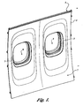
- FIGURE 1 depicts a section of an aircraft cabin sidewall 1 with a cabin side view of a pair of snap-in window assemblies 3 according to the present invention.
- an inner perimeter 7 of an outer side wall 5 of the aircraft cabin sidewall 1 serves as the structure for defining an opening 9 for the snap-in window assemblies 3.
- FIGURE 2 depicts a section view of an outer sidewall 5 opposite an aircraft cabin sidewall 1 view of a pair of snap-in window assemblies 3 according to the present invention.
- the outer sidewall 5 contains an inner perimeter 7 defining an opening 9.
- the opening 9 serves to index a location for an inner window frame 11 and an outer window frame 13.
- the snap-in window assembly includes a sun-shade guide tract 15.
- the inner window frame 11 is attached to the outer sidewall 5 in the indexed location of the opening 9 via releasable coupling devices 17 and 19 as is further illustrated in FIGURES 3-6.
- the releasable coupling devices 17 and 19 facilitate the coupling and decoupling of the inner window frame 11 from the opening 9 in the outer sidewall 5 without having to remove the outer sidewall 5 to access the outer window frame 13 or the inner window frame 11.
- the outer window frame 13 is attached to the inner window frame 11 via a plurality of window snap fasteners 21 contiguously spaced and aligned along a perimeter of the inner and outer window frames 11 and 13, respectively.
- the window snap fasteners 21 are one or more tension clip devices releasably secured to an accommodating protrusion 23 on the outer window frame 13 and that further snap over an accommodating protrusion 24 along the perimeter of the inner window frame 11.
- the window snap fasteners 21 further serve to align the inner window frame 11 and the outer window frame 13 in the indexed opening 9 of the inner perimeter 7 of the outer sidewall 5.
- the inner window frame 11 and outer window frame 13 are coupled via the plurality of window snap fasteners 21 contiguously spaced and aligned along a perimeter of the inner and outer window frames 11 and 13, respectively as further described above, prior to their coupling to form the snap-in window assemblies 3 readily attachable to the outer sidewall 5 via the coupling devices 17 and 19.
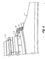
- FIGURE 3 depicts a view in the direction of an aircraft cabin of an upper portion of a window assembly 3 that is attached to an outer sidewall 5.
- the outer window frame 13 is readily attached to the inner window frame 11 by a plurality of window snap fasteners 21 as further illustrated in FIGURE 2.
- the window snap fasteners 21 are one or more tension clip devices releasably secured to an accommodating protrusion 23 on the outer window frame 13 and that further snap over an accommodating protrusion 24 along the perimeter of the inner window frame 11.
- the snap fasteners 21 further permit detaching the inner window frame 11 and the outer window frame 13 from the outer sidewall 5 as a single window assembly 3 without having to remove the outer sidewall 5.
- the snap fasteners 21 can be secured to the inner window frame 11 and snap over a protruding surface along the perimeter of the outer window frame 13. It will be appreciated that the snap fasteners 21 are suitably any device that uses force tension to facilitate the securing and attaching of both the outer window frame 13 and the inner window frame 11 in a single window assembly 3.
- the inner window frame 11 is releasably attached to the outer sidewall 5 via one or more spring clips 25 that are evenly spaced within the interior surface of a shaped flange 27 extending along the outer top perimeter of the inner window frame 11.
- the spring clips 25 are secured to the outer sidewall 5 so that the spring clips 25 securely affix the shaped flange 27 to the outer sidewall 5.
- the spring clips 25 provide compressive spring force to secure assembly of the inner window frame 11 to the outer sidewall 5 in a snap-together assembly.
- the shaped flange 27 further provides one ore more sun-shade guide tract lugs 22.
- the sun-shade guide track lugs 22 facilitate the attaching of a sun-shade track 15 to the shaped flange 27.
- the outer window frame 13 is further releasably attached to the inner window frame 11 via the coupling of a deformable flange 29 of the outer window frame 13 and the shaped flange 27.
- the deformable flange extends along a portion of the outer top perimeter of the outer window frame 13 and is designed such that it is formed to define a pliable hook as further depicted in FIGURE 4.
- the deformable flange allows the coupling of the inner window frame 11 and the outer window frame 13 without the use additional coupling hardware, for example affixable brackets.
- the deformable flange 29 is replaced with a similarly positioned rigid flange.
- the rigid flange is formed so as to define a shape that accommodating for the outer window frame 13 to engage the shaped flange 27 in a coupling snap-together assembly.
- FIGURE 4 depicts a side view of an upper portion of an outer window frame 13 to show the coupling of the outer window frame 13 to the inner window frame 11 attached to a an outer sidewall 5.
- spring clips 25 are attached to the outer sidewall 5 and secure a shaped flange 25 to the outer sidewall 5.
- a deformable flange 29 of the outer window frame 13 is positioned over the top center of the inner window frame 11 and is snapped over the shaped flange 27 so that both the inner window frame 11 and the outer window frame 13 are engaged in a snap-together assembly.
- the dotted lines 28 depict the snap-together range of motion to show the deformable flange 29 engaging the shaped flange 25.
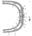
- FIGURE 5 depicts a view in the direction of an aircraft cabin of a lower portion of a window assembly 3 readily attached to an outer sidewall 5.
- An outer window frame 13 is attached to an inner window frame 11 by a plurality of window snap fasteners 21 as further illustrated in FIGURES 2 and 3.
- the snap fasteners 21 further permit the decoupling of the inner window frame 11 and the outer window frame 13 from the outer sidewall 5 as a single window assembly without having to remove the outer sidewall 5.
- the snap fasteners 21 can be secured to the inner window frame 11 and snap over a protruding surface along the perimeter of the outer window frame 13. It will be appreciated that the snap fasteners 21 are suitably any device that uses force tension to facilitate the securing and attaching both the outer window frame 13 and the inner window frame 11 in a single window assembly.
- the inner window frame 13 is further releasably attached to the outer sidewall 5 via at least one retention spring clip 31 centered within the interior surface of a gusset 33 supported shaped flange 35 extending along the lower bottom perimeter of the inner window frame 13.
- the retention spring clip 31 is secured to the outer sidewall 5 so that the spring clip securely affixes the shaped flange 35 to the outer sidewall 5.
- the spring clip 31 provides compressive spring force to secure assembly of the inner window frame 11 to the outer sidewall 5 in a snap-together assembly.
- Gusset 33 provides maximum strength at the corner of the shaped flange 35 and is designed so that the load of the outer window frame is borne by the gussets 33 and not solely by the shaped flange 35.
- the inner window frame 13 is releasably coupled to the outer sidewall 5 via a pawl latch mechanism 37.
- FIGURE 6 depicts a side view of a lower portion of an outer window frame to show the coupling of an outer window frame 13 to an inner window frame 11 attached to an outer sidewall 5.
- the inner window frame 11 is releasably attached to an outer sidewall 5 via a pawl latch mechanism 37.
- the pawl latch mechanism 37 operates by rotating a latch 39, having a pawl finger 41 radially attached to its shank 43.
- the rotation of the latch 39 is indexed to one or more index points 43 to visually or tactily provide a relative position for opening or closing the latch to couple or decouple the inner window frame 11 from the outer sidewall 5.
- a press of the pawl finger 41 through an access hole brings 47 the latch 39 under a shaped flange 35 of an inner window assembly 11 thereby releasably coupling the outer window assembly 13 to the inner window assembly 11 and held in position by coiled springs 45.
- a pull of the pawl finger 41 in the opposite rotation provides release of the pawl latch, thus providing a quick decoupling of the outer window frame 13 from the inner window frame 11 and disengaging the coiled springs 45.
- the access hole 47 provides access to the pawl finger 41 from the cabin sidewall 1.
- the pawl latch mechanism 37 further allows a window assembly 3 to remain in an open position not totally decoupled from the outer sidewall 5. This would allow, for example, maintenance access to both sides of the inner window frame 11 and outer window frame 13 without having to decouple the whole window assembly 3 from the outer sidewall 5.
- the pawl latch mechanism has a widely-adjustable grip range or has self-adjusting spring pawl latches.
Landscapes
- Engineering & Computer Science (AREA)
- Mechanical Engineering (AREA)
- Aviation & Aerospace Engineering (AREA)
- Window Of Vehicle (AREA)
- Connection Of Plates (AREA)
- Wing Frames And Configurations (AREA)
- Door And Window Frames Mounted To Openings (AREA)
Claims (5)
- Anordnung umfassend:- eine Seitenwand (1) eines Flugzeugs, wobei die Seitenwand einen inneren Umfang (7) aufweist, welcher eine Öffnung (9) definiert;- ein lösbares einschnappendes Fenster (3), wobei das Fenster umfasst:- einen inneren Fensterrahmen (11), welcher an der Seitenwand benachbart zu dem inneren Umfang anbringbar ist, wobei der innere Fensterrahmen eine erste Öffnung definiert;- einen äußeren Fensterrahmen (13), welcher an dem inneren Fensterrahmen benachbart zu der ersten Öffnung anbringbar ist, wobei der äußere Fensterrahmen eine zweite Öffnung definiert;- erste obere Koppelvorrichtungen (17), welche eine oder mehrere Federklemmen (25) umfassen, die an einer äußeren Oberfläche der Seitenwand befestigt sind und für eine Druckfederkraft sorgen, um eine Anordnung eines geformten Flansches (27) des inneren Fensterrahmens an der äußeren Seitenwand in einer zusammenschnappenden Anordnung zu befestigen; und- zweite untere Koppelvorrichtungen (19), welche einen Klauenverriegelungsmechanismus (37) umfassen, um den inneren Fensterrahmen (11) an der äußeren Oberfläche der Seitenwand (5) zu befestigen, wobei der Klauenverriegelungsmechanismus einen Klauenfinger (41) und eine Verriegelung (39) aufweist, wobei der Klauenfinger radial an einem Schafft (43) angebracht ist und betrieben wird, indem sich die Verriegelung durch ein Zugangsloch (47) dreht, um das Fenster mit der Seitenwand zu koppeln oder von der Seitenwand zu entkoppeln.
- Anordnung nach Anspruch 1, einen verformbaren Flansch (29) des äußeren Fensterrahmens umfassend, wobei der Flansch über der oberen Mitte des inneren Fensterrahmens angeordnet ist und über einem geformten Flansch einschnappt, um in Eingriff mit dem inneren Fensterrahmen und dem äußeren Fensterrahmen in einer zusammenschnappenden Anordnung zu kommen.
- Anordnung nach Anspruch 2, wobei der verformbare Flansch (29) der ersten Koppelvorrichtungen in der Form eines biegbaren Hakens geformt ist.
- Anordnung nach Anspruch 1, 2 oder 3, wobei der äußere Fensterrahmen durch eine Mehrzahl von Befestigungsvorrichtungen an dem inneren Fensterrahmen angebracht ist, wobei die Befestigungsvorrichtungen Schnappbefestiger (21) aufweisen, welche lösbar an einem angepassten Vorsprung (23) auf dem äußeren Fensterrahmen (13) befestigt sind und welche weiter über einen Umfang des inneren Fensterrahmens (11) einschnappen.
- Verfahren zum lösbaren Koppeln einer einschnappenden Fensteranordnung an einer Seitenwand eines Flugzeugs, wobei das Verfahren umfasst:- Anbringen eines inneren Fensterrahmens (11) an der Seitenwand benachbart zu einem inneren Umfang (7), wobei der innere Fensterrahmen eine erste Öffnung definiert;- Anbringen eines äußeren Fensterrahmens (13), welcher leicht an den inneren Fensterrahmen benachbart zu der ersten Öffnung anbringbar ist, wobei der äußere Fensterrahmen eine zweite Öffnung definiert;- Montieren des inneren Fensterrahmens an der äußeren Seitenwand durch erste obere Koppelvorrichtungen (17) in eine zusammenschnappende Anordnung, wobei die Vorrichtungen eine oder mehrere Federklemmen (25) umfassen, welche an einer äußeren Oberfläche der Seitenwand befestigt sind und einen geformten Flansch (27) des inneren Fensterrahmens an der Seitenwand befestigen und für eine Druckfederkraft sorgen, um die Anordnung zu befestigen; und- Befestigen des inneren Fensterrahmens (11) an der äußeren Oberfläche der Seitenwand (5) durch zweite untere Koppelvorrichtungen (19), welche einen Klauenverriegelungsmechanismus (37) umfassen, wobei der Klauenverriegelungsmechanismus einen Klauenfinger (41) und eine Verriegelung (39) aufweist, wobei der Klauenfinger radial an einem Schafft (43) angebracht ist und betrieben wird, indem sich die Verriegelung durch ein Zugangsloch (47) dreht, um das Fenster an der Seitenwand zu koppeln oder von der Seitenwand zu entkoppeln.
Applications Claiming Priority (2)
| Application Number | Priority Date | Filing Date | Title |
|---|---|---|---|
| US10/047,186 US6786453B2 (en) | 2001-10-25 | 2001-10-25 | Snap-in window assembly and method |
| US47186 | 2001-10-25 |
Publications (3)
| Publication Number | Publication Date |
|---|---|
| EP1306302A2 EP1306302A2 (de) | 2003-05-02 |
| EP1306302A3 EP1306302A3 (de) | 2004-05-12 |
| EP1306302B1 true EP1306302B1 (de) | 2006-12-13 |
Family
ID=21947522
Family Applications (1)
| Application Number | Title | Priority Date | Filing Date |
|---|---|---|---|
| EP02079233A Revoked EP1306302B1 (de) | 2001-10-25 | 2002-10-11 | Fensteranordnung mit Einschnappverbinder und Verfahren |
Country Status (5)
| Country | Link |
|---|---|
| US (1) | US6786453B2 (de) |
| EP (1) | EP1306302B1 (de) |
| BR (1) | BR0204325A (de) |
| CA (1) | CA2405923C (de) |
| DE (1) | DE60216698T2 (de) |
Families Citing this family (40)
| Publication number | Priority date | Publication date | Assignee | Title |
|---|---|---|---|---|
| US6871822B2 (en) * | 2003-04-18 | 2005-03-29 | The Boeing Company | Apparatus and methods of attaching panels to support structures |
| DE102004025375B4 (de) * | 2004-05-24 | 2010-01-28 | Airbus Deutschland Gmbh | Fensterrahmen für Flugzeuge |
| US7118069B2 (en) * | 2004-12-02 | 2006-10-10 | The Boeing Company | Integrated window belt system for aircraft cabins |
| US7210655B2 (en) * | 2004-12-03 | 2007-05-01 | The Boeing Company | Reconfigurable interior sidewall |
| US20070079490A1 (en) * | 2005-09-12 | 2007-04-12 | Dimario Joseph | Method of mounting a panel over an opening |
| US7661626B2 (en) * | 2005-10-28 | 2010-02-16 | The Boeing Company | Window assembly retaining system |
| US7843469B2 (en) * | 2006-07-21 | 2010-11-30 | The Boeing Company | Overlaying information onto a view for electronic display |
| US8650499B2 (en) * | 2006-07-21 | 2014-02-11 | The Boeing Company | Selecting and identifying view overlay information for electronic display |
| US8123168B2 (en) * | 2006-08-24 | 2012-02-28 | The Boeing Company | Window assembly and method for a mobile platform |
| US20080092476A1 (en) * | 2006-10-11 | 2008-04-24 | Little Cottage Company | Window and window frame construction |
| US8290642B2 (en) * | 2007-03-02 | 2012-10-16 | The Boeing Company | Electronic flight bag having filter system and method |
| US7823833B2 (en) * | 2007-03-05 | 2010-11-02 | The Boeing Company | Window installation method and apparatus |
| USD592584S1 (en) * | 2007-04-18 | 2009-05-19 | Airbus Deutschland Gmbh | Side lining panel for an aircraft cabin |
| CA123617S (en) * | 2007-06-11 | 2009-03-25 | Mitsubishi Heavy Ind Ltd | Vehicle window panel |
| USD589872S1 (en) * | 2007-09-20 | 2009-04-07 | Airbus Sas | Aircraft window |
| USD588977S1 (en) * | 2007-10-04 | 2009-03-24 | Airbus Sas | Aircraft cabin wall |
| USD654008S1 (en) * | 2007-11-19 | 2012-02-14 | British Airways P.L.C. | Window frame |
| US8370111B2 (en) * | 2008-03-31 | 2013-02-05 | The Boeing Company | System and method for forming optimized perimeter surveillance |
| US8686854B2 (en) * | 2008-03-31 | 2014-04-01 | The Boeing Company | System and method for forming optimized perimeter surveillance |
| US20110167994A1 (en) * | 2008-09-30 | 2011-07-14 | Au-Yeung Honmartin K | Pyrotechnic egress system |
| USD719895S1 (en) | 2010-05-13 | 2014-12-23 | Embraer S.A. | Aircraft interior sidewall |
| US8701260B1 (en) * | 2010-12-21 | 2014-04-22 | The Boeing Company | Removal of aircraft window reveal |
| CA2824054C (en) * | 2011-01-13 | 2018-01-02 | Aerospace Technologies Group, Inc. | Systems and methods for installing motorized window shade mechanism in aircraft |
| US8944381B2 (en) | 2011-03-25 | 2015-02-03 | The Boeing Company | Aircraft window and installation method |
| USD691552S1 (en) | 2012-03-16 | 2013-10-15 | John A. Saavedra | Door for overhead storage compartment for an aircraft interior |
| USD691551S1 (en) | 2012-03-16 | 2013-10-15 | John A. Saavedra | Door for overhead storage compartment for an aircraft interior |
| USD692820S1 (en) | 2012-03-16 | 2013-11-05 | John A. Saavedra | Side panel for aircraft cabin |
| USD672703S1 (en) * | 2012-03-16 | 2012-12-18 | Saavedra John A | Side panel for aircraft cabin |
| US9506247B2 (en) | 2014-03-28 | 2016-11-29 | Steelcase Inc. | Transparent panel system for partitions |
| US10329759B2 (en) | 2012-09-17 | 2019-06-25 | Steelcase Inc. | Floor-to-ceiling partition wall assembly |
| CA2917564C (en) * | 2013-07-12 | 2021-07-20 | Learjet Inc. | Door for an aircraft |
| US9109353B1 (en) * | 2013-08-13 | 2015-08-18 | The Boeing Company | Mounting assembly and method for connecting sidewall panels to a support structure |
| US9592902B2 (en) * | 2014-02-17 | 2017-03-14 | The Boeing Company | Hatch assembly for use in a vehicle and method of assembling the same |
| US10112695B2 (en) | 2015-08-20 | 2018-10-30 | Georgian Aerospace Llc | Receptacle, payload assembly and related methods for an aircraft |
| US20170051552A1 (en) | 2015-08-21 | 2017-02-23 | Deco Flash, Llc | Clip Fastener System For a Window |
| USD861537S1 (en) * | 2017-03-02 | 2019-10-01 | Newtl | Bus |
| US10309146B1 (en) | 2018-01-08 | 2019-06-04 | Deco Flash Llc | Screwless window fastening system |
| RU182607U1 (ru) * | 2018-03-30 | 2018-08-23 | Акционерное общество "Корпорация "Стратегические пункты управления" АО "Корпорация "СПУ - ЦКБ ТМ" | Дверное обрамление |
| US11407486B2 (en) * | 2019-11-14 | 2022-08-09 | The Boeing Company | Window clamp system for a vehicle |
| CN111776246B (zh) * | 2020-07-13 | 2023-03-31 | 山东太古飞机工程有限公司 | 一种用于飞机客舱玻璃组件清洁与组装的辅助工装 |
Family Cites Families (15)
| Publication number | Priority date | Publication date | Assignee | Title |
|---|---|---|---|---|
| US3050790A (en) * | 1959-09-09 | 1962-08-28 | Lockheed Aircraft Corp | Openable aircraft window |
| US3191240A (en) * | 1961-04-20 | 1965-06-29 | Slaman Albert | Multi-pane window panels |
| US3906669A (en) * | 1973-03-02 | 1975-09-23 | Lockheed Aircraft Corp | Window assembly |
| US4364533A (en) | 1980-11-13 | 1982-12-21 | The Boeing Company | Sidewall panel window assembly and method of installing |
| US4541595A (en) | 1983-03-28 | 1985-09-17 | Heath-Tecna Precision Structures | Removable interior window unit for aircraft |
| US4742664A (en) * | 1986-10-07 | 1988-05-10 | Hope's Architectural Products, Inc. | Snap-in glazing bead |
| US4877658A (en) | 1988-02-22 | 1989-10-31 | Calhoon Gale R | Window liner for use in aircraft |
| USD331215S (en) | 1990-03-12 | 1992-11-24 | Msa Aircraft Interior Products, Inc. | Combined window panel and shade for aircraft |
| US5271581A (en) * | 1992-05-29 | 1993-12-21 | Irish Michael J | Window clip for aircraft |
| JPH0752890A (ja) | 1993-08-19 | 1995-02-28 | Jamco Corp | 航空機の機体の客室側面に装備される窓構造 |
| US5826824A (en) * | 1996-11-08 | 1998-10-27 | Sikorsky Aircraft Corporation | Emergency egress system for aircraft |
| US5816307A (en) | 1997-02-19 | 1998-10-06 | Msa Aircraft Interior Products, Inc. | Aircraft window assembly having a circular, rotatable lens |
| AT404925B (de) | 1997-07-25 | 1999-03-25 | Fischer Adv Components Gmbh | Fenstereinheit für flugzeugkabinen |
| US6168112B1 (en) * | 1998-02-14 | 2001-01-02 | Daimlerchrysler Aerospace Airbus Gmbh | Double pane window for an aircraft cabin |
| US6082674A (en) | 1998-09-16 | 2000-07-04 | Mcdonnel Douglas Corporation | Aircraft window escuthcheon assembly |
-
2001
- 2001-10-25 US US10/047,186 patent/US6786453B2/en not_active Expired - Fee Related
-
2002
- 2002-10-01 CA CA002405923A patent/CA2405923C/en not_active Expired - Fee Related
- 2002-10-11 DE DE60216698T patent/DE60216698T2/de not_active Revoked
- 2002-10-11 EP EP02079233A patent/EP1306302B1/de not_active Revoked
- 2002-10-22 BR BR0204325-4A patent/BR0204325A/pt not_active IP Right Cessation
Also Published As
| Publication number | Publication date |
|---|---|
| EP1306302A3 (de) | 2004-05-12 |
| EP1306302A2 (de) | 2003-05-02 |
| CA2405923A1 (en) | 2003-04-25 |
| DE60216698T2 (de) | 2007-10-04 |
| BR0204325A (pt) | 2003-09-16 |
| US20030080252A1 (en) | 2003-05-01 |
| CA2405923C (en) | 2006-07-11 |
| DE60216698D1 (de) | 2007-01-25 |
| US6786453B2 (en) | 2004-09-07 |
Similar Documents
| Publication | Publication Date | Title |
|---|---|---|
| EP1306302B1 (de) | Fensteranordnung mit Einschnappverbinder und Verfahren | |
| US6227491B1 (en) | Window unit for aircraft cabins | |
| US7118069B2 (en) | Integrated window belt system for aircraft cabins | |
| KR101666235B1 (ko) | 차량 내부 라이닝용 체결 장치 | |
| EP1348621B1 (de) | Fensterbefestigungssystem und Methode zur Fensterbefestigung | |
| EP1842705B1 (de) | Trägerplatte für fahrzeugtüren und verfahren zur montage dieser trägerplatte | |
| EP0262704A3 (de) | Flugzeugkabinenabdeckung und Isolierstoffhalteteil, wirksam auch als Isolierzwischenstück | |
| JP2015519248A (ja) | 車両用の採光用開口システム | |
| JPH07149151A (ja) | 車両用ドア組付体 | |
| US20170342756A1 (en) | Pulley rivet for installation of pulleys for window regulator systems | |
| US6336293B1 (en) | Door of lavatory unit | |
| KR100316953B1 (ko) | 차량의 도어 래치 커버 | |
| GB2315187A (en) | Loudspeaker basket with integral or attached fixing means | |
| CN212406409U (zh) | 一种双开尾门锁的主锁结构 | |
| KR101902740B1 (ko) | 드릴 작업 없이 장착되는 지게차 캐빈용 도어커튼 및 창틀 | |
| US4819985A (en) | Vehicle sunroof hinge | |
| US7562846B2 (en) | Window retaining system | |
| JPH0433940Y2 (de) | ||
| KR100279571B1 (ko) | 자동차의 도어트림 취부구조 | |
| CN201517325U (zh) | 可调节半固定卡扣 | |
| KR101870333B1 (ko) | 풀다운 창호의 방충망 장치 | |
| JPH1082233A (ja) | サッシ | |
| KR19980023799U (ko) | 버스의 도어글라스 잠금장치 | |
| KR19990043170A (ko) | 버스의 쿨러덕트 취부구조 | |
| JPH06264669A (ja) | 接続枠取付構造 |
Legal Events
| Date | Code | Title | Description |
|---|---|---|---|
| PUAI | Public reference made under article 153(3) epc to a published international application that has entered the european phase |
Free format text: ORIGINAL CODE: 0009012 |
|
| AK | Designated contracting states |
Designated state(s): AT BE BG CH CY CZ DE DK EE ES FI FR GB GR IE IT LI LU MC NL PT SE SK TR |
|
| AX | Request for extension of the european patent |
Extension state: AL LT LV MK RO SI |
|
| PUAL | Search report despatched |
Free format text: ORIGINAL CODE: 0009013 |
|
| AK | Designated contracting states |
Kind code of ref document: A3 Designated state(s): AT BE BG CH CY CZ DE DK EE ES FI FR GB GR IE IT LI LU MC NL PT SE SK TR |
|
| AX | Request for extension of the european patent |
Extension state: AL LT LV MK RO SI |
|
| 17P | Request for examination filed |
Effective date: 20040712 |
|
| 17Q | First examination report despatched |
Effective date: 20040825 |
|
| AKX | Designation fees paid |
Designated state(s): DE FR GB |
|
| GRAP | Despatch of communication of intention to grant a patent |
Free format text: ORIGINAL CODE: EPIDOSNIGR1 |
|
| GRAS | Grant fee paid |
Free format text: ORIGINAL CODE: EPIDOSNIGR3 |
|
| GRAA | (expected) grant |
Free format text: ORIGINAL CODE: 0009210 |
|
| AK | Designated contracting states |
Kind code of ref document: B1 Designated state(s): DE FR GB |
|
| REG | Reference to a national code |
Ref country code: GB Ref legal event code: FG4D |
|
| REF | Corresponds to: |
Ref document number: 60216698 Country of ref document: DE Date of ref document: 20070125 Kind code of ref document: P |
|
| ET | Fr: translation filed | ||
| PLBI | Opposition filed |
Free format text: ORIGINAL CODE: 0009260 |
|
| PLAX | Notice of opposition and request to file observation + time limit sent |
Free format text: ORIGINAL CODE: EPIDOSNOBS2 |
|
| 26 | Opposition filed |
Opponent name: AIRBUS FRANCE SAS/AIRBUS UK LIMITED/ A Effective date: 20070913 |
|
| PLBB | Reply of patent proprietor to notice(s) of opposition received |
Free format text: ORIGINAL CODE: EPIDOSNOBS3 |
|
| RAP2 | Party data changed (patent owner data changed or rights of a patent transferred) |
Owner name: THE BOEING COMPANY |
|
| RDAF | Communication despatched that patent is revoked |
Free format text: ORIGINAL CODE: EPIDOSNREV1 |
|
| PGFP | Annual fee paid to national office [announced via postgrant information from national office to epo] |
Ref country code: DE Payment date: 20081201 Year of fee payment: 7 |
|
| RDAG | Patent revoked |
Free format text: ORIGINAL CODE: 0009271 |
|
| STAA | Information on the status of an ep patent application or granted ep patent |
Free format text: STATUS: PATENT REVOKED |
|
| PGFP | Annual fee paid to national office [announced via postgrant information from national office to epo] |
Ref country code: FR Payment date: 20081018 Year of fee payment: 7 |
|
| 27W | Patent revoked |
Effective date: 20090124 |
|
| GBPR | Gb: patent revoked under art. 102 of the ep convention designating the uk as contracting state |
Effective date: 20090124 |
|
| PGFP | Annual fee paid to national office [announced via postgrant information from national office to epo] |
Ref country code: GB Payment date: 20081029 Year of fee payment: 7 |