EP1306255A2 - Antriebsvorrichtung für ein Fahrzeug, insbesondere dieselelektrische Antriebsordnung mit Wandlergetriebebaueinheit - Google Patents
Antriebsvorrichtung für ein Fahrzeug, insbesondere dieselelektrische Antriebsordnung mit Wandlergetriebebaueinheit Download PDFInfo
- Publication number
- EP1306255A2 EP1306255A2 EP02020017A EP02020017A EP1306255A2 EP 1306255 A2 EP1306255 A2 EP 1306255A2 EP 02020017 A EP02020017 A EP 02020017A EP 02020017 A EP02020017 A EP 02020017A EP 1306255 A2 EP1306255 A2 EP 1306255A2
- Authority
- EP
- European Patent Office
- Prior art keywords
- converter
- transmission
- drive
- gear
- branch
- Prior art date
- Legal status (The legal status is an assumption and is not a legal conclusion. Google has not performed a legal analysis and makes no representation as to the accuracy of the status listed.)
- Withdrawn
Links
Images


Classifications
-
- B—PERFORMING OPERATIONS; TRANSPORTING
- B60—VEHICLES IN GENERAL
- B60W—CONJOINT CONTROL OF VEHICLE SUB-UNITS OF DIFFERENT TYPE OR DIFFERENT FUNCTION; CONTROL SYSTEMS SPECIALLY ADAPTED FOR HYBRID VEHICLES; ROAD VEHICLE DRIVE CONTROL SYSTEMS FOR PURPOSES NOT RELATED TO THE CONTROL OF A PARTICULAR SUB-UNIT
- B60W20/00—Control systems specially adapted for hybrid vehicles
-
- B—PERFORMING OPERATIONS; TRANSPORTING
- B60—VEHICLES IN GENERAL
- B60K—ARRANGEMENT OR MOUNTING OF PROPULSION UNITS OR OF TRANSMISSIONS IN VEHICLES; ARRANGEMENT OR MOUNTING OF PLURAL DIVERSE PRIME-MOVERS IN VEHICLES; AUXILIARY DRIVES FOR VEHICLES; INSTRUMENTATION OR DASHBOARDS FOR VEHICLES; ARRANGEMENTS IN CONNECTION WITH COOLING, AIR INTAKE, GAS EXHAUST OR FUEL SUPPLY OF PROPULSION UNITS IN VEHICLES
- B60K1/00—Arrangement or mounting of electrical propulsion units
-
- B—PERFORMING OPERATIONS; TRANSPORTING
- B60—VEHICLES IN GENERAL
- B60K—ARRANGEMENT OR MOUNTING OF PROPULSION UNITS OR OF TRANSMISSIONS IN VEHICLES; ARRANGEMENT OR MOUNTING OF PLURAL DIVERSE PRIME-MOVERS IN VEHICLES; AUXILIARY DRIVES FOR VEHICLES; INSTRUMENTATION OR DASHBOARDS FOR VEHICLES; ARRANGEMENTS IN CONNECTION WITH COOLING, AIR INTAKE, GAS EXHAUST OR FUEL SUPPLY OF PROPULSION UNITS IN VEHICLES
- B60K6/00—Arrangement or mounting of plural diverse prime-movers for mutual or common propulsion, e.g. hybrid propulsion systems comprising electric motors and internal combustion engines
- B60K6/20—Arrangement or mounting of plural diverse prime-movers for mutual or common propulsion, e.g. hybrid propulsion systems comprising electric motors and internal combustion engines the prime-movers consisting of electric motors and internal combustion engines, e.g. HEVs
- B60K6/22—Arrangement or mounting of plural diverse prime-movers for mutual or common propulsion, e.g. hybrid propulsion systems comprising electric motors and internal combustion engines the prime-movers consisting of electric motors and internal combustion engines, e.g. HEVs characterised by apparatus, components or means specially adapted for HEVs
- B60K6/26—Arrangement or mounting of plural diverse prime-movers for mutual or common propulsion, e.g. hybrid propulsion systems comprising electric motors and internal combustion engines the prime-movers consisting of electric motors and internal combustion engines, e.g. HEVs characterised by apparatus, components or means specially adapted for HEVs characterised by the motors or the generators
-
- B—PERFORMING OPERATIONS; TRANSPORTING
- B60—VEHICLES IN GENERAL
- B60K—ARRANGEMENT OR MOUNTING OF PROPULSION UNITS OR OF TRANSMISSIONS IN VEHICLES; ARRANGEMENT OR MOUNTING OF PLURAL DIVERSE PRIME-MOVERS IN VEHICLES; AUXILIARY DRIVES FOR VEHICLES; INSTRUMENTATION OR DASHBOARDS FOR VEHICLES; ARRANGEMENTS IN CONNECTION WITH COOLING, AIR INTAKE, GAS EXHAUST OR FUEL SUPPLY OF PROPULSION UNITS IN VEHICLES
- B60K6/00—Arrangement or mounting of plural diverse prime-movers for mutual or common propulsion, e.g. hybrid propulsion systems comprising electric motors and internal combustion engines
- B60K6/20—Arrangement or mounting of plural diverse prime-movers for mutual or common propulsion, e.g. hybrid propulsion systems comprising electric motors and internal combustion engines the prime-movers consisting of electric motors and internal combustion engines, e.g. HEVs
- B60K6/22—Arrangement or mounting of plural diverse prime-movers for mutual or common propulsion, e.g. hybrid propulsion systems comprising electric motors and internal combustion engines the prime-movers consisting of electric motors and internal combustion engines, e.g. HEVs characterised by apparatus, components or means specially adapted for HEVs
- B60K6/36—Arrangement or mounting of plural diverse prime-movers for mutual or common propulsion, e.g. hybrid propulsion systems comprising electric motors and internal combustion engines the prime-movers consisting of electric motors and internal combustion engines, e.g. HEVs characterised by apparatus, components or means specially adapted for HEVs characterised by the transmission gearings
- B60K6/365—Arrangement or mounting of plural diverse prime-movers for mutual or common propulsion, e.g. hybrid propulsion systems comprising electric motors and internal combustion engines the prime-movers consisting of electric motors and internal combustion engines, e.g. HEVs characterised by apparatus, components or means specially adapted for HEVs characterised by the transmission gearings with the gears having orbital motion
-
- B—PERFORMING OPERATIONS; TRANSPORTING
- B60—VEHICLES IN GENERAL
- B60K—ARRANGEMENT OR MOUNTING OF PROPULSION UNITS OR OF TRANSMISSIONS IN VEHICLES; ARRANGEMENT OR MOUNTING OF PLURAL DIVERSE PRIME-MOVERS IN VEHICLES; AUXILIARY DRIVES FOR VEHICLES; INSTRUMENTATION OR DASHBOARDS FOR VEHICLES; ARRANGEMENTS IN CONNECTION WITH COOLING, AIR INTAKE, GAS EXHAUST OR FUEL SUPPLY OF PROPULSION UNITS IN VEHICLES
- B60K6/00—Arrangement or mounting of plural diverse prime-movers for mutual or common propulsion, e.g. hybrid propulsion systems comprising electric motors and internal combustion engines
- B60K6/20—Arrangement or mounting of plural diverse prime-movers for mutual or common propulsion, e.g. hybrid propulsion systems comprising electric motors and internal combustion engines the prime-movers consisting of electric motors and internal combustion engines, e.g. HEVs
- B60K6/22—Arrangement or mounting of plural diverse prime-movers for mutual or common propulsion, e.g. hybrid propulsion systems comprising electric motors and internal combustion engines the prime-movers consisting of electric motors and internal combustion engines, e.g. HEVs characterised by apparatus, components or means specially adapted for HEVs
- B60K6/38—Arrangement or mounting of plural diverse prime-movers for mutual or common propulsion, e.g. hybrid propulsion systems comprising electric motors and internal combustion engines the prime-movers consisting of electric motors and internal combustion engines, e.g. HEVs characterised by apparatus, components or means specially adapted for HEVs characterised by the driveline clutches
-
- B—PERFORMING OPERATIONS; TRANSPORTING
- B60—VEHICLES IN GENERAL
- B60K—ARRANGEMENT OR MOUNTING OF PROPULSION UNITS OR OF TRANSMISSIONS IN VEHICLES; ARRANGEMENT OR MOUNTING OF PLURAL DIVERSE PRIME-MOVERS IN VEHICLES; AUXILIARY DRIVES FOR VEHICLES; INSTRUMENTATION OR DASHBOARDS FOR VEHICLES; ARRANGEMENTS IN CONNECTION WITH COOLING, AIR INTAKE, GAS EXHAUST OR FUEL SUPPLY OF PROPULSION UNITS IN VEHICLES
- B60K6/00—Arrangement or mounting of plural diverse prime-movers for mutual or common propulsion, e.g. hybrid propulsion systems comprising electric motors and internal combustion engines
- B60K6/20—Arrangement or mounting of plural diverse prime-movers for mutual or common propulsion, e.g. hybrid propulsion systems comprising electric motors and internal combustion engines the prime-movers consisting of electric motors and internal combustion engines, e.g. HEVs
- B60K6/22—Arrangement or mounting of plural diverse prime-movers for mutual or common propulsion, e.g. hybrid propulsion systems comprising electric motors and internal combustion engines the prime-movers consisting of electric motors and internal combustion engines, e.g. HEVs characterised by apparatus, components or means specially adapted for HEVs
- B60K6/40—Arrangement or mounting of plural diverse prime-movers for mutual or common propulsion, e.g. hybrid propulsion systems comprising electric motors and internal combustion engines the prime-movers consisting of electric motors and internal combustion engines, e.g. HEVs characterised by apparatus, components or means specially adapted for HEVs characterised by the assembly or relative disposition of components
-
- B—PERFORMING OPERATIONS; TRANSPORTING
- B60—VEHICLES IN GENERAL
- B60K—ARRANGEMENT OR MOUNTING OF PROPULSION UNITS OR OF TRANSMISSIONS IN VEHICLES; ARRANGEMENT OR MOUNTING OF PLURAL DIVERSE PRIME-MOVERS IN VEHICLES; AUXILIARY DRIVES FOR VEHICLES; INSTRUMENTATION OR DASHBOARDS FOR VEHICLES; ARRANGEMENTS IN CONNECTION WITH COOLING, AIR INTAKE, GAS EXHAUST OR FUEL SUPPLY OF PROPULSION UNITS IN VEHICLES
- B60K6/00—Arrangement or mounting of plural diverse prime-movers for mutual or common propulsion, e.g. hybrid propulsion systems comprising electric motors and internal combustion engines
- B60K6/20—Arrangement or mounting of plural diverse prime-movers for mutual or common propulsion, e.g. hybrid propulsion systems comprising electric motors and internal combustion engines the prime-movers consisting of electric motors and internal combustion engines, e.g. HEVs
- B60K6/42—Arrangement or mounting of plural diverse prime-movers for mutual or common propulsion, e.g. hybrid propulsion systems comprising electric motors and internal combustion engines the prime-movers consisting of electric motors and internal combustion engines, e.g. HEVs characterised by the architecture of the hybrid electric vehicle
- B60K6/46—Series type
-
- F—MECHANICAL ENGINEERING; LIGHTING; HEATING; WEAPONS; BLASTING
- F16—ENGINEERING ELEMENTS AND UNITS; GENERAL MEASURES FOR PRODUCING AND MAINTAINING EFFECTIVE FUNCTIONING OF MACHINES OR INSTALLATIONS; THERMAL INSULATION IN GENERAL
- F16H—GEARING
- F16H47/00—Combinations of mechanical gearing with fluid clutches or fluid gearing
- F16H47/06—Combinations of mechanical gearing with fluid clutches or fluid gearing the fluid gearing being of the hydrokinetic type
- F16H47/08—Combinations of mechanical gearing with fluid clutches or fluid gearing the fluid gearing being of the hydrokinetic type the mechanical gearing being of the type with members having orbital motion
- F16H47/085—Combinations of mechanical gearing with fluid clutches or fluid gearing the fluid gearing being of the hydrokinetic type the mechanical gearing being of the type with members having orbital motion with at least two mechanical connections between the hydrokinetic gearing and the mechanical gearing
-
- B—PERFORMING OPERATIONS; TRANSPORTING
- B60—VEHICLES IN GENERAL
- B60K—ARRANGEMENT OR MOUNTING OF PROPULSION UNITS OR OF TRANSMISSIONS IN VEHICLES; ARRANGEMENT OR MOUNTING OF PLURAL DIVERSE PRIME-MOVERS IN VEHICLES; AUXILIARY DRIVES FOR VEHICLES; INSTRUMENTATION OR DASHBOARDS FOR VEHICLES; ARRANGEMENTS IN CONNECTION WITH COOLING, AIR INTAKE, GAS EXHAUST OR FUEL SUPPLY OF PROPULSION UNITS IN VEHICLES
- B60K1/00—Arrangement or mounting of electrical propulsion units
- B60K2001/001—Arrangement or mounting of electrical propulsion units one motor mounted on a propulsion axle for rotating right and left wheels of this axle
-
- B—PERFORMING OPERATIONS; TRANSPORTING
- B60—VEHICLES IN GENERAL
- B60Y—INDEXING SCHEME RELATING TO ASPECTS CROSS-CUTTING VEHICLE TECHNOLOGY
- B60Y2400/00—Special features of vehicle units
- B60Y2400/20—Energy converters
- B60Y2400/204—Generator sets, engine and generator as one unit
-
- B—PERFORMING OPERATIONS; TRANSPORTING
- B60—VEHICLES IN GENERAL
- B60Y—INDEXING SCHEME RELATING TO ASPECTS CROSS-CUTTING VEHICLE TECHNOLOGY
- B60Y2400/00—Special features of vehicle units
- B60Y2400/42—Clutches or brakes
-
- B—PERFORMING OPERATIONS; TRANSPORTING
- B60—VEHICLES IN GENERAL
- B60Y—INDEXING SCHEME RELATING TO ASPECTS CROSS-CUTTING VEHICLE TECHNOLOGY
- B60Y2400/00—Special features of vehicle units
- B60Y2400/42—Clutches or brakes
- B60Y2400/426—Hydrodynamic couplings, e.g. torque converters
-
- F—MECHANICAL ENGINEERING; LIGHTING; HEATING; WEAPONS; BLASTING
- F16—ENGINEERING ELEMENTS AND UNITS; GENERAL MEASURES FOR PRODUCING AND MAINTAINING EFFECTIVE FUNCTIONING OF MACHINES OR INSTALLATIONS; THERMAL INSULATION IN GENERAL
- F16H—GEARING
- F16H37/00—Combinations of mechanical gearings, not provided for in groups F16H1/00 - F16H35/00
- F16H37/02—Combinations of mechanical gearings, not provided for in groups F16H1/00 - F16H35/00 comprising essentially only toothed or friction gearings
- F16H37/06—Combinations of mechanical gearings, not provided for in groups F16H1/00 - F16H35/00 comprising essentially only toothed or friction gearings with a plurality of driving or driven shafts; with arrangements for dividing torque between two or more intermediate shafts
- F16H37/08—Combinations of mechanical gearings, not provided for in groups F16H1/00 - F16H35/00 comprising essentially only toothed or friction gearings with a plurality of driving or driven shafts; with arrangements for dividing torque between two or more intermediate shafts with differential gearing
- F16H37/0833—Combinations of mechanical gearings, not provided for in groups F16H1/00 - F16H35/00 comprising essentially only toothed or friction gearings with a plurality of driving or driven shafts; with arrangements for dividing torque between two or more intermediate shafts with differential gearing with arrangements for dividing torque between two or more intermediate shafts, i.e. with two or more internal power paths
- F16H37/084—Combinations of mechanical gearings, not provided for in groups F16H1/00 - F16H35/00 comprising essentially only toothed or friction gearings with a plurality of driving or driven shafts; with arrangements for dividing torque between two or more intermediate shafts with differential gearing with arrangements for dividing torque between two or more intermediate shafts, i.e. with two or more internal power paths at least one power path being a continuously variable transmission, i.e. CVT
- F16H2037/0866—Power-split transmissions with distributing differentials, with the output of the CVT connected or connectable to the output shaft
-
- Y—GENERAL TAGGING OF NEW TECHNOLOGICAL DEVELOPMENTS; GENERAL TAGGING OF CROSS-SECTIONAL TECHNOLOGIES SPANNING OVER SEVERAL SECTIONS OF THE IPC; TECHNICAL SUBJECTS COVERED BY FORMER USPC CROSS-REFERENCE ART COLLECTIONS [XRACs] AND DIGESTS
- Y02—TECHNOLOGIES OR APPLICATIONS FOR MITIGATION OR ADAPTATION AGAINST CLIMATE CHANGE
- Y02T—CLIMATE CHANGE MITIGATION TECHNOLOGIES RELATED TO TRANSPORTATION
- Y02T10/00—Road transport of goods or passengers
- Y02T10/60—Other road transportation technologies with climate change mitigation effect
- Y02T10/62—Hybrid vehicles
Definitions
- the invention relates to a drive device for a vehicle, in particular a not track-bound vehicle, in detail with the characteristics from the Preamble of claim 1.
- Drive systems in the form of a hybrid drive i.e. a combination of one Internal combustion engine and an electric motor
- the special print by J. M. Voith GmbH, G 1407 discloses a diesel-electric drive system for commercial vehicles, in particular for city buses. This includes at least one with at least one Drive wheel can be coupled at least indirectly and as a so-called wheel motor functioning electric motor, which preferably as a transverse flux machine is executed.
- the individual wheel drive motors are at least one Inverter unit supplied with electrical power. Furthermore, one is in Traction operation, i.e.
- a generator operable electrical machine in normal driving with power flow direction from Internal combustion engine to the electric motor driving the drive wheel, provided as a generator operable electrical machine, which also can preferably be designed as a transverse flux machine.
- the in Traction operation as a generator operated electrical machine is mechanical with an internal combustion engine, in particular a diesel engine, coupled.
- the generator is with those that act as wheel drive motors Electric motors electrically coupled.
- To generate the electrical power the electrical machine that can be operated as a generator by a Four-quadrant inverter controlled.
- For specifying the setpoints of the Wheel motors (torque, speed) and the speed control of the A superordinate driving control is provided for the internal combustion engine, which among others is able to evaluate the driver's request.
- the one as a generator Operable electrical machine is at least in the traction mode Generator operated, which is why this only as a generator referred to as.
- Other diesel-electric drives for non-railbound Vehicles are, for example, from the European patent EP 0 527 145 B1 known.
- the drive arrangement according to this document is characterized in that the internal combustion engine and the Generator to a so-called internal combustion engine generator assembly were summarized.
- the invention was therefore based on the object of a drive device to develop the type mentioned at the outset such that the disadvantage mentioned is avoided, in particular a sufficiently high torque to the Axes from the electric motor acting as the drive motor when starting off To provide, the overall drive device with optimal efficiency to be operated. Furthermore, the constructive and control engineering Keeping effort to a minimum and compatibility with other gear concepts for vehicles.
- a converter gear unit arranged in a drive device comprising at least one Internal combustion engine, one with the internal combustion engine in Direction of power flow in traction mode considered operable as a generator electrical machine and an electrical motor that functions as a traction motor Drive motor, between the electric as a traction motor Drive motor and the drive wheels a converter gear unit arranged.
- the converter transmission assembly includes at least one hydrodynamic speed / torque converter and mechanical Gear elements.
- the hydrodynamic speed / torque converter is thereby in power split to the mechanical gear elements used.
- the one on the input shaft is the Transducer gear unit output divided into several branches and on an output shaft of the converter transmission assembly again merged.
- the necessary distribution and / or collective gear can also be used as elements for additional mechanical gear stages be used.
- such an arrangement enables the advantages of a to use hydrodynamic power transmission, in particular that Ratio between the input and output speed automatically without control continuously according to the load on the output side, i.e. on the wheels, to adjust. Since the torque conversion when the turbine wheel is at a standstill is maximum, the maximum torque is available for starting or accelerating to disposal.
- the hydrodynamic transmission branch the drive device, in particular the diesel-electric drive group, separated from the vehicle and only a small one Residual torque are transmitted so that the vehicle does not stall is possible.
- the hydrodynamic speed / torque converter enables it from the drive unit, i.e. the one that acts as the drive motor Drive motor, increasing torque provided on the output shaft and thus converting to a higher starting torque.
- the converter gear unit Basic versions There are essentially three for the design of the converter gear unit Basic versions available. It is generally between executions a power split with a transfer case, an execution of a Power split with collective gearbox and a mixture of the two distinguished.
- the hydrodynamic speed / torque converter in a first gear branch a transfer case, which is downstream of the input shaft of the converter gear unit, assigned.
- the first gear branch forms an output of the Transfer case.
- the second gear branch forms a further second output of the transfer case.
- the second gear branch which is also called mechanical Gearbox branch is referred to, for example, only from one simple transmission wave exist. However, in theory it is also conceivable that in the second mechanical transmission branch further mechanical Gear stages or transmission devices are arranged.
- the converter turbine stands still at the approach point.
- both in the area of the transmission input shaft Transfer case for distribution on both transmission branches, the mechanical and the hydrodynamic transmission branch, and in front of the output shaft from the Converter gear unit can be arranged a collective gear.
- the hydrodynamic transmission branch and the mechanical transmission branch are included each with an output from the transfer case and an input to the Coupled gearbox.
- the external power split is the Transducer in one of the two branches of the branch. This will only part of the power is transferred hydraulically.
- the entire transmission therefore has higher efficiency than the hydrodynamic speed / torque converter alone because the total losses are getting smaller.
- the hydrodynamic speed / torque converters can also be smaller run as a single converter that increases the overall power would have transferred.
- Speed ratio determining factor is for example a direct link or a fixed translation
- a differential gear for example, determines the torque ratio.
- the mechanical gear elements can be in the form of spur gear stages, Planetary gear sets u. ⁇ . or mixed forms of the aforementioned become.
- a branching with transfer case in the form of a Differential converter gearbox used.
- At least one planetary gear preferably a planetary gear set, distributes the input power, i.e. the on the input shaft of the converter transmission unit to a power hydraulic and a mechanical branch.
- the input power i.e. the on the input shaft of the converter transmission unit
- a power hydraulic and a mechanical branch are the speeds of the individual branch shafts divided by the epicyclic gear so that the Pump speed increases when the speed of the other branch drops, so there is a strong retroactive effect of the combined with the power split Converter on the drive side, i.e. the electric, which acts as the drive motor Drive motor.
- the converter gearbox as Differential converter gearbox is the torque converter with the Planetary gear set, i.e.
- the converter gearbox to perform the above functions is in the Various drive arrangements can be integrated.
- the as a generator in Electric machine operated by traction can be spatially separated from the electric drive motor acting as the traction motor; this is particularly the case when the traction motor is in the area of the axle drive is arranged. In this case there is only an electrical coupling between the two drive units over a large part of the vehicle.
- Another conceivable possibility is that which can be operated as a generator electrical machine and the electrical motor that functions as the drive motor Arrange the drive motor in close proximity to each other.
- the Power transmission from the electric, which acts as a traction motor The drive motor for the axle drive or for driving the wheels then takes place via Shafting.
- the converter transmission assembly is preferably between the electric drive motor and the shaft train acting as the traction motor arranged.
- An arrangement in the direction of power flow behind the shaft train is also conceivable, but leads to the fact that the power transmission over the Shaft train takes place at high speeds.
- the resulting ones Vibration problems can be solved by arranging the Transducer assembly avoided in front of the shaft train in the direction of power flow become.
- a preferred embodiment is that which can be operated as a generator electrical machine, the inverter assembly and the drive motor summarize functioning electric drive motor in one assembly.
- This assembly then forms what is known as an electrical transmission a conventional automatic transmission in terms of installation space can be equated.
- the electrical machine which can be operated as a generator and the as are preferably Traction motor electric drive motor acting as a transverse flux machine executed. There is also the possibility of electrical machines same type and design for the generator and the drive motor to use.
- the invention also provides a method for Increase on the vehicle axles of a non-track-bound vehicle of the torque transmitted with the diesel-electric drive and at the same time Achieving optimal efficiency and a possible one hydrodynamic power transmission over a wider operating range Available.
- a starting process of the non-track-bound vehicle Becomes one of the controls reported, this initiates the commissioning of the hydrodynamic Speed / torque converter on the converter gear unit.
- purely hydraulic power transmission will be used by the traction motor Provided torque converted into a higher starting torque.
- the speed of the vehicle or one in the driving state is then measured with the aid of sensors determined at least indirectly characterizing size.
- the hydrodynamically transmitted power component is reduced and the mechanically transferable increases. If a predetermined value for the Driving speed or a driving state at least indirectly characterizing size is reached, so in turn a signal to a Control device transmitted.
- This signal causes the Control device, the hydrodynamic speed / torque converter to bridge completely, or to take it out of the torque transmission, for example, by decoupling or determining the impeller, which is a results in purely mechanical power transmission.
- the drive motor is then stopped over the mechanical transmission branch of the converter transmission assembly with the Final drive in connection.
- the predetermined Vehicle speed value or the current vehicle status at least indirectly characterizing value is the time in which the Torque conversion during the starting process is hydraulically-mechanically effective, set.
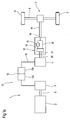
- FIG. 1 schematically illustrates an embodiment of a Drive device 1 for a vehicle, in particular not rail-bound vehicle.
- the drive device 1 comprises a Internal combustion engine 2, which is preferably designed as a diesel engine is an electrical that can be operated as a generator in the traction mode of the vehicle Machine 3 and one acting as a traction motor, in traction as a motor operable electric drive motor 4.
- the electric drive motor 4 is at least indirectly with the wheels 5 and 6 to be driven or in illustrated case coupled to the axle drive 7 of the vehicle axle 8.
- the electric machine 3 that can be operated as a generator in traction mode is included the internal combustion engine 2 mechanically coupled.
- the mechanical Coupling can, as shown in the example, be rigid in the simplest case.
- the coupling between the electrical that can be operated as a generator in traction mode Machine 3 and the electric drive motor 4 functioning as a traction motor takes place via an electrical coupling 10.
- This comprises a first line 11 which the electric machine that can be operated as a generator in traction mode with a Converter assembly 12, consisting of a generator-inverter 12a and a motor inverter 12b, and a line 13, which the motor inverter 12b with the electrical function as the traction motor Drive motor 4 couples.
- the electrical machines, especially the as Generator in traction operation electric machine 3 and the electric drive motor 4 are each preferably as Transverse flux machine executed.
- both for the generator and for the electric drive motor 4 each a transverse flux machine of the same type, for example, a transverse flux machine to generate the same power use.
- the electrical machine 3, which can be operated as a generator, can be connected to the electric drive machine 4 are flanged.
- a particularly compact one Drive arrangement arises if instead of a direct flange connection the electric machine 3 which can be operated as a generator to the as a traction motor Acting electric drive motor 4, the generator 3, the converter part 12 and the electric drive motor 4 to a so-called electric Gear unit can be summarized.
- This electrical gear unit can then be used instead of, for example, an automatic transmission.
- the different drive concepts namely Powertrain with automatic transmission or diesel-electric powertrain, can be exchanged very easily and without major modifications.
- a converter transmission assembly 15 is arranged between the drive motor Acting electric drive motor 4 and the wheels 4, 5 to be driven or the vehicle axis 8, in the case shown between the electrical Drive motor 4 and the shaft train 14, in the case shown between the electrical Drive motor 4 and the shaft train 14, a converter transmission assembly 15 is arranged.
- a converter transmission assembly 15 Under a converter transmission assembly 15, a transmission understood, in which a hydrodynamic speed / torque converter 16 coupled with additional mechanical elements to make a change or expansion of the operating range of the transmission and thus in correspondingly to achieve the drive device 1.
- the hydrodynamic converter 16 in the converter transmission assembly 15 in external power split arranged. This means that after division the power into two separate branches, a first branch 19 and a second Branch 20, the hydrodynamic speed / torque converter 16 only in one of the two branches. This means that only part of the power is hydraulic transfer.
- the overall transmission, in particular the converter transmission assembly 15, therefore has a higher efficiency than the hydrodynamic speed / torque converter 16 on its own, since the total losses are lower.
- the hydrodynamic speed / torque converter can also be smaller are designed as a hydrodynamic converter 16, which the Total power to transfer.
- the converter transmission assembly 15 is preferably in shape a differential converter gearbox executed.
- This includes the hydrodynamic speed / torque converter 16 in a first hydrodynamic branch 19 and further a planetary gear set 21.
- Der Planetary gear set 21, comprising at least a first link 22, a second link 23 as well as a third link 24, with the speed / torque converter 16 in combined in such a way that the first link 22 with the impeller P of the hydrodynamic speed / torque converter 16, the second link 23 of the planetary gear set 21 with the drive shaft, i.e. the input shaft 17 and the third link 24 of the planetary gear set 21 with the output shaft, i.e.
- the Output shaft 18 of the converter transmission assembly 15 is connected to the over a freewheel or a switchable planetary gear also the converter turbine wheel T drives.
- the hydrodynamic speed / torque converter 16 can for example as in "hydrodynamics in drive technology", Krausskopfverlag, Mainz, disclosed in 1987, be trained. To execute a Differential converter transmission is also on this document, on pp. 158-195, directed. The disclosure content in this regard is fully included in this Registration included.
- the hydrodynamically transmitted power component is reduced via the hydrodynamic speed / torque converter (16) due to the effect of the differential, while the mechanically transmissible component increases.
- the hydrodynamic speed / torque converter is removed from the power transmission at the operating point of its best efficiency and the power is transmitted purely mechanically, for example by automatically bridging or decoupling the first gear branch 19 or the converter from the first gear branch 19 or by fixing the pump wheel P of the hydrodynamic Speed / torque converter 16.
- a so-called lock-up clutch is used to bridge the hydrodynamic speed / torque converter 16.
- the differential converter principle enables an economical Power transmission, the advantage of hydrodynamic Energy transfer in the start-up area, especially a steady and stable one Tractive force curve over a large speed range are retained can.
- the execution of the converter transmission assembly 15 in the form of a Differential converter transmission is a preferred embodiment. Possible however, are other arrangements of a hydrodynamic speed / torque converter in external branch of performance with others mechanical gear elements, for example spur gear stages.
- the the as Driving motor acting electric drive motor 4 in traction mode downstream converter gear unit 15 allows the use of Advantages of hydrodynamic power transmission in the approach area, i.e. a stepless low-noise torque conversion with low wear Operating mode, the hydrodynamic speed / torque converter works automatically when filling.
- the hydrodynamic Speed / torque converter 16 in the starting area to increase the Torque translation i.e. the one that acts as the drive motor electric drive motor 4 to the vehicle axle 8 or the wheels 5 and 6 the shaft 14 output torque.
- the disadvantages of a hydrodynamic Power transmission with increasing speed especially in Synchronous operating range, are excluded by in this case the Power is no longer transmitted hydraulically, but increasingly done mechanically.
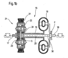
- FIG. 1b illustrates a section A corresponding to FIG. 1a from FIG Drive device 1.
- the input shaft is 17, the output shaft with 18, the planetary gear set with 21 and the hydrodynamic Speed / torque converter designated 16.
- the first link of the Planetary gear set 22 is formed here by the planet carrier.
- the sun gear s acts as the third link Sun gear r.
- the planetary gear set 21 functions here as a distribution gear. This the torque applied to the input shaft 17 branches to one hydrodynamic branch 19 via the hydrodynamic speed / torque converter 16 and a mechanical branch 20 via a Intermediate shaft 30.
- the hydrodynamic power component is from the impeller P of the hydrodynamic speed / torque converter via the turbine wheel T and the freewheel F also transferred to the intermediate shaft 30.
- the mechanically transmitted power increases with increasing driving speed to.
- Has the hydrodynamic speed / torque converter the Operating point of its best efficiency is exceeded automatically switched a purely mechanical operating state by a Braking device 31 stops the pump wheel P.
- the turbine wheel T then remains also stand, since the freewheel F is entrained by the intermediate shaft 30 prevented.
- the switch itself can also be done by the driver, for example via the accelerator pedal or a driving switch are influenced.
- Such Influenceability by means of a control or regulating device 32 is shown in FIG. 1c shown.
- FIG. 1c illustrates an embodiment corresponding to FIG. 1a additional control or regulating device 32.
- This comprises at least one Control device 33.
- Control device 33 has at least one input 34 on which the current driving speed and / or Acceleration signals are present.
- a comparison device which the currently determined Driving speed and / or acceleration values with predeterminable values compares.
- the braking device 31 on the planetary gear set 21 such actuates that the power flow between the input shaft 17 and the hydrodynamic speed / torque converter 16 is interrupted.
- the Torque converter 16 is then no longer on the power transmission involved.
- the choice of the predetermined value is preferably made such that after reaching a speed that the hydrodynamic converter with operates optimal efficiency, this removed from the power flow becomes.
- the control of the braking device 31 can be fully automatic or also, for example, by the driver using the accelerator pedal or the driving switch to be influenced. For some applications, it can also be advantageous to Make switching in the partial load area so dependent that lower driving speed is switched.
- the second mechanical transmission branch 20 this with additional switching stages Mistake. In particular, this can lead to a considerable expansion of the Lead operating area of the overall drive assembly.
- the hydrodynamic speed-speed converter Provide possibilities for changing the degree of filling in the circuit. It exists then the ability to drive a particular device for a variety of Use cases with the same components.
- the hydrodynamic speed / torque converter can be one Synchronous converter or act as a so-called reverse converter.
- synchronous converter in addition to a high starting tractive effort, a steady one automatic adaptation to the load achieved.
- the counter-current converter in which the axial flow through the turbine impeller T opposite to the pump impeller P rotates, in addition to a high startup conversion, a favorable efficiency curve and under the condition of an appropriate interpretation in connection with a low engine speed depression can be achieved with an input differential.
- hydrodynamic torque / speed converter 16 can also can be used as a braking device.
- FIGS. 2a and 2b illustrate possible embodiments of a Converter gear assembly 15, in particular a differential converter gear.
- the individual converter transmission modules 15a and 15b comprise here a respective hydrodynamic branch 19a or 19b and a second one mechanical transmission branch 20a or 20b.
- the hydrodynamic speed / torque converter 16a in terms of construction arranged between a transfer case 40 and a collective gear 41.
- the hydrodynamic speed / torque converter 16a is in the first hydrodynamic branch 19a arranged. This forms an output 42 transfer case 40.
- a second output 44 from transfer case 40 is formed by the mechanical gear branch.
- the mechanical gear part comprises a connecting shaft 45 which is connected to a collective gear 41 is coupled.
- the output of the mechanical transmission branch thus forms one Input of the collective gear 41, while another second input 46 from hydrodynamic torque / speed converter 16a, in particular the Coupling with the turbine wheel T, is formed.
- another second input 46 from hydrodynamic torque / speed converter 16a in particular the Coupling with the turbine wheel T, is formed.
- Be on the collective gear 41 the individual power components, which over the hydrodynamic first branch 19a and the mechanical branch 20a were brought together again.
- FIG. 2b shows a structure that is similar in principle, but differentiates it themselves with regard to the construction of transfer cases and collective gears.
- the concrete structural design of a converter gear unit, in particular a differential converter gear unit is at the discretion of Professional.
- Other versions for converter gearboxes are the printing unit "Hydrodynamics in drive technology", United specialist publishers, Krausskopf Engineer Digest, Mainz, 1987, pages 153-195.
- the Disclosure content of this printing group regarding the designs of Differential converter transmissions are hereby intended to fully cover the disclosure content this registration.
Landscapes
- Engineering & Computer Science (AREA)
- Mechanical Engineering (AREA)
- Transportation (AREA)
- Chemical & Material Sciences (AREA)
- Combustion & Propulsion (AREA)
- Automation & Control Theory (AREA)
- General Engineering & Computer Science (AREA)
- Arrangement Of Transmissions (AREA)
- Electric Propulsion And Braking For Vehicles (AREA)
Abstract
Description
- Fig. 1a
- den schematischen Aufbau eines erfindungsgemäß gestalteten Antriebsstranges mit einem Wandlergetriebe in Form eines Differentialwandlers;
- Fig. 1b
- einen Ausschnitt A aus Fig. 1a;
- Fig. 1c
- einen Antriebsstrang entsprechend der Figuren 1a und 1b mit zugeordneter Steuer- und/oder Regelvorrichtung;
- Fig. 2
- weitere Ausführungsvarianten für eine Wandlergetriebeeinheit mit äußerer Leistungsverzweigung in schematischer Darstellung.
Des weiteren besteht jedoch auch die Möglichkeit, das Pumpenrad des hydrodynamischen Drehzahl-/Drehmomentenwandlers festzusetzen.
Claims (19)
- Antriebsvorrichtung für ein Fahrzeug, insbesondere ein nicht spurgebundenes Fahrzeug,1.1 mit einer Verbrennungskraftmaschine (2);1.2 mit einer im Traktionsbetrieb als Generator E betreibbaren elektrischen Maschine (3);1.3 mit einem wenigstens mittelbar mit einem Achsantrieb (7) und/oder den anzutreibenden Rädern (5, 6) koppelbaren elektrischen Antriebsmotor (4); gekennzeichnet durch die folgenden Merkmale:1.4 zwischen dem elektrischen Antriebsmotor und den anzutreibenden Rädem (5, 6) bzw. dem Achsantrieb (7) ist eine Drehzahl-/Drehmomentenübertragungs- und Wandlungseinrichtung in Form einer Wandlergetriebebaueinheit (15) mit Leistungsverzweigung angeordnet;1.5 die Wandlergetriebebaueinheit (15) umfaßt wenigstens einen hydrodynamischen Drehzahl-/Drehmomentenwandler (16, 16a, 16b, 16c), welcher in einem ersten Zweig der Leistungsverzweigung (19) angeordnet ist.
- Antriebsvorrichtung nach Anspruch 1, dadurch gekennzeichnet, daß der zweite Zweig (20) der Wandlergetriebbaueinheit (15) mechanische Übertragungselemente umfaßt.
- Antriebsvorrichtung nach einem der Ansprüche 1 oder 2, gekennzeichnet durch die folgenden Merkmale:3.1 eine Eingangswelle (17) der Wandlergetriebebaueinheit (15) ist mit dem ersten Getriebezweig (19) und dem zweiten Getriebezweig (20) gekoppelt;3.2 die beiden Getriebezweige (19, 20), erster Getriebezweig (19) und zweiter Getriebezweig (20), sind über ein Sammelgetriebe (41) mit der Ausgangswelle der Wandlergetriebebaueinheit gekoppelt.
- Antriebsvorrichtung nach einem der Ansprüche 1 bis 3, dadurch gekennzeichnet, daß die Wandlergetriebebaueinheit (15) ein Verteilergetriebe (21, 40) umfaßt, welches die Eingangswelle (17) der Wandlergetriebebaueinheit (15) mit den beiden Getriebezweigen (19, 20), erster Getriebezweig (19) und zweiter Getriebezweig (20), koppelt.
- Antriebsvorrichtung nach Anspruch 4, dadurch gekennzeichnet, daß das Verteilergetriebe (21, 40) als Differentialgetriebe, umfassend wenigstens einen Planetenradsatz, ausgeführt ist.
- Antriebsvorrichtung nach Anspruch 5, gekennzeichnet durch die folgenden Merkmale:6.1 ein erstes Glied (22) des Differentialgetriebes ist mit einem Pumpenrad (P) des hydrodynamischen Drehmomenten-/Drehzahlwandlers (16) gekoppelt;6.2 ein zweites Glied (23) des Differentialgetriebes ist mit der Eingangswelle (17) der Wandlergetriebebaueinheit gekoppelt;6.3 ein drittes Glied (24) des Differentialgetriebes steht mit der Ausgangswelle (18) der Wandlergetriebebaueinheit (15) wenigstens mittelbar in Drehverbindung;6.4 es sind Mittel vorgesehen zur Kopplung des Turbinenrades (T) des hydrodynamischen Drehmomenten-/Drehzahlwandlers (16) mit der Ausgangswelle (18) der Wandlergetriebebaueinheit.
- Antriebsvorrichtung nach Anspruch 6, dadurch gekennzeichnet, daß das Mittel ein Freilauf (F) ist.
- Antriebsvorrichtung nach Anspruch 6, dadurch gekennzeichnet, daß das Mittel ein schaltbares Planetengetriebe ist.
- Antriebsvorrichtung nach einem der Ansprüche 6 bis 8, dadurch gekennzeichnet, daß dem Differential eine Bremseinrichtung (31) derart zugeordnet ist, daß bei Betätigung das Pumpenrad (P) festgesetzt wird.
- Antriebsvorrichtung nach einem der Ansprüche 1 bis 9, dadurch gekennzeichnet, daß Mittel vorgesehen sind, welche den ersten Leistungszweig (19) von der Eingangswelle (17) der Wandlergetriebeübertragungseinheit (15) abkoppeln.
- Antriebsvorrichtung nach Anspruch 10, dadurch gekennzeichnet, daß eine Steuervorrichtung (32) vorgesehen ist, die die Mittel (F/31) derart ansteuert, daß bei Anfahrvorgängen die hydrodynamische Leistungsübertragung ab Erreichen eines bestimmten Drehzahlverhältnisses zwischen der Eingangswelle (17) und der Ausgangswelle (18) der Wandlergetriebebaueinheit (15) unterbricht.
- Antriebsvorrichtung nach einem der Ansprüche 1 bis 11, dadurch gekennzeichnet, daß der Antriebsmotor (4) im Fahrzeugchassis angeordnet ist.
- Antriebsanordnung nach einem der Ansprüche 1 bis 12, dadurch gekennzeichnet, daß der Antriebsmotor (4) in einer Zentralmotorenanordnung angeordnet ist.
- Antriebsvorrichtung nach einem der Ansprüche 1 bis 13, dadurch gekennzeichnet, daß die als Generator (3) betreibbare elektrische Maschine und der Antriebsmotor (4) zu einer elektrischen Getriebebaueinheit zusammengefaßt sind.
- Antriebsvorrichtung nach einem der Ansprüche 1 bis 14, dadurch gekennzeichnet, daß der Antriebsmotor (4) eine Transversalflußmaschine ist.
- Antriebsvorrichtung nach einem der Ansprüche 1 bis 15, dadurch gekennzeichnet, daß die als Generator betreibbare elektrische Maschine (3) als Transversalflußmaschine ausgeführt ist.
- Antriebsvorrichtung nach einem der Ansprüche 1 bis 16, gekennzeichnet durch die folgenden Merkmale:17.1 die Kopplung zwischen dem elektrischen Antriebsmotor (4) und dem Achsantrieb (7) und/oder den anzutreibenden Rädern (5, 6) erfolgt über einen Wellenstrang (14);17.2 die Wandlergetriebebaueinheit (15) ist in Kraftflußrichtung im Fraktionsbetrieb betrachtet zwischen der Wandlergetriebebaueinheit (15) und dem Wellenstrang (14) angeordnet.
- Verfahren zur Erhöhung des auf die Fahrzeugachsen eines nicht spurgebundenen Fahrzeuges mit einem dieselelektrisch übertragenen Drehmoment mit folgenden Schritten:18.1 es wird ein Anfahrvorgang des Fahrzeuges erfaßt;18.2 bei Erfassung des Anfahrvorganges wird zur Erzeugung eines überhöhten Anfahrdrehmomentes die vom Antriebsmotor erzeugte Leistung hydrodynamisch und mechanisch übertragen, wobei mit zunehmenden Drehzahlverhältnissen zwischen der Eingangswelle und der Ausgangswelle der Wandlergetriebebaueinheit der hydraulisch übertragene Leistungsanteil verringert wird;18.3 bei Erreichen eines vorbestimmten Fahrgeschwindigkeitswertes und/oder einer den aktuellen Fahrzustand wenigstens mittelbar charakterisierenden Größe, wird die hydraulische Leistungsübertragung durch Umgehung des hydrodynamischen Drehzahl-/Drehmomentenwandlers unterbrochen.
- Verfahren nach Anspruch 18, dadurch gekennzeichnet, daß die Unterbrechung der hydraulischen Leistungsübertragung durch Herstellung eines mechanischen Durchtriebes erfolgt.
Applications Claiming Priority (2)
| Application Number | Priority Date | Filing Date | Title |
|---|---|---|---|
| DE10152488 | 2001-10-24 | ||
| DE10152488A DE10152488A1 (de) | 2001-10-24 | 2001-10-24 | Antriebsvorrichtung für ein Fahrzeug, insbesondere dieselelektrische Antriebsordnung mit Wandlergetriebebaueinheit |
Publications (2)
| Publication Number | Publication Date |
|---|---|
| EP1306255A2 true EP1306255A2 (de) | 2003-05-02 |
| EP1306255A3 EP1306255A3 (de) | 2005-11-16 |
Family
ID=7703574
Family Applications (1)
| Application Number | Title | Priority Date | Filing Date |
|---|---|---|---|
| EP02020017A Withdrawn EP1306255A3 (de) | 2001-10-24 | 2002-09-06 | Antriebsvorrichtung für ein Fahrzeug, insbesondere dieselelektrische Antriebsordnung mit Wandlergetriebebaueinheit |
Country Status (2)
| Country | Link |
|---|---|
| EP (1) | EP1306255A3 (de) |
| DE (1) | DE10152488A1 (de) |
Cited By (2)
| Publication number | Priority date | Publication date | Assignee | Title |
|---|---|---|---|---|
| CN108674171A (zh) * | 2018-05-23 | 2018-10-19 | 杜春洪 | 一种电动车自动离合混合动力驱动系统 |
| CN114801690A (zh) * | 2022-05-13 | 2022-07-29 | 中国煤炭科工集团太原研究院有限公司 | 一种油电双动力传动系统及双动力胶轮运输车 |
Families Citing this family (11)
| Publication number | Priority date | Publication date | Assignee | Title |
|---|---|---|---|---|
| DE102004037181A1 (de) * | 2004-07-30 | 2006-03-23 | Zf Friedrichshafen Ag | Antrieb für ein Elektrofahrzeug |
| DE102004048754A1 (de) * | 2004-10-05 | 2006-04-13 | Voith Turbo Gmbh & Co. Kg | Pod-Schiffsantrieb mit Getriebe |
| DE102006014856A1 (de) * | 2006-03-30 | 2007-10-04 | Siemens Ag | Antriebssystem für ein Nutzfahrzeug, insbesondere für den Mineneinsatz |
| DE102007022735A1 (de) * | 2007-05-11 | 2008-11-13 | Voith Patent Gmbh | Fahrzeugantrieb und Verfahren zum Betrieb desselben |
| US20110179891A1 (en) | 2007-09-20 | 2011-07-28 | Busch Jorg | Automatic transmission having hydrodynamic converter |
| DE102011018236A1 (de) * | 2011-04-19 | 2012-10-25 | Voith Patent Gmbh | Vorrichtung zur Kraftübertragung |
| CN103213488A (zh) * | 2013-03-28 | 2013-07-24 | 吴先德 | 一种汽车燃油发动机、电机混合两用动力转换机构 |
| DE102018128650B4 (de) * | 2018-11-15 | 2025-10-09 | Schaeffler Technologies AG & Co. KG | Hybrid-Antriebssystem für ein elektrisch zumindest teilweise antreibbares Kraftfahrzeug |
| CN109435670A (zh) * | 2018-12-26 | 2019-03-08 | 苏州绿控传动科技股份有限公司 | 一种基于单变速箱的混合动力耦合桥 |
| CN109435671A (zh) * | 2018-12-26 | 2019-03-08 | 苏州绿控传动科技股份有限公司 | 一种基于两变速箱的混合动力耦合桥 |
| DE102020125347B4 (de) | 2020-09-29 | 2025-05-15 | Voith Patent Gmbh | E-Motorgetriebeeinheit für einen Antriebsstrang |
Citations (1)
| Publication number | Priority date | Publication date | Assignee | Title |
|---|---|---|---|---|
| EP0527145B1 (de) | 1990-04-06 | 1996-07-24 | Magnet-Motor Gesellschaft Für Magnetmotorische Technik Mbh | Elektrofahrzeug mit einzeln gesteuerten antriebs-elektromotoren |
Family Cites Families (2)
| Publication number | Priority date | Publication date | Assignee | Title |
|---|---|---|---|---|
| WO1983001230A1 (en) * | 1981-10-07 | 1983-04-14 | Amlin Propulsion Inc | Vehicle power system |
| GB9012365D0 (en) * | 1990-06-02 | 1990-07-25 | Jaguar Cars | Motor vehicles |
-
2001
- 2001-10-24 DE DE10152488A patent/DE10152488A1/de not_active Withdrawn
-
2002
- 2002-09-06 EP EP02020017A patent/EP1306255A3/de not_active Withdrawn
Patent Citations (1)
| Publication number | Priority date | Publication date | Assignee | Title |
|---|---|---|---|---|
| EP0527145B1 (de) | 1990-04-06 | 1996-07-24 | Magnet-Motor Gesellschaft Für Magnetmotorische Technik Mbh | Elektrofahrzeug mit einzeln gesteuerten antriebs-elektromotoren |
Non-Patent Citations (2)
| Title |
|---|
| "Automotive Engineering", February 1995, article "Drive Systems with Permanent Magnet Synchron Motors", pages: 75 - 81 |
| "Der Nahverkehr", June 1994, article B. WOST, R. MOLLER, A. LANGE: "Ein elektrischer Einzelradantrieb für Citybusse der Zukunft", pages: 1 - 7 |
Cited By (2)
| Publication number | Priority date | Publication date | Assignee | Title |
|---|---|---|---|---|
| CN108674171A (zh) * | 2018-05-23 | 2018-10-19 | 杜春洪 | 一种电动车自动离合混合动力驱动系统 |
| CN114801690A (zh) * | 2022-05-13 | 2022-07-29 | 中国煤炭科工集团太原研究院有限公司 | 一种油电双动力传动系统及双动力胶轮运输车 |
Also Published As
| Publication number | Publication date |
|---|---|
| DE10152488A1 (de) | 2002-06-06 |
| EP1306255A3 (de) | 2005-11-16 |
Similar Documents
| Publication | Publication Date | Title |
|---|---|---|
| DE102017218513B4 (de) | Getriebe für ein Kraftfahrzeug, Kraftfahrzeugantriebsstrang mit einem solchen Ge-triebe und Verfahren zum Betreiben eines solchen Getriebes | |
| EP1126987B1 (de) | Hybridgetriebe, insbesondere für kraftfahrzeuge | |
| EP1954542B1 (de) | Hybridantrieb für fahrzeuge sowie verfahren zur steuerung eines getriebes für einen hybridantrieb | |
| DE60209568T2 (de) | Kraftübertragungsvorrichtung mit mindestens zwei planetengetriebezügen | |
| DE102006044500B4 (de) | Elektromechanisches Getriebe mit Eingangsverzweigung, zwei festen Drehzahlverhältnissen und einer Betriebsart | |
| EP1280677A2 (de) | Hybridgetriebe, insbesondere für kraftfahrzeuge | |
| DE102007043173A1 (de) | Elektrisch verstellbares Hybridgetriebe mit einem über Zahnräder hergestellten Rückwärtsmodus, das einen einzigen Motor/Generator verwendet | |
| DE102008008644A1 (de) | Elektrisch verstellbares Getriebe mit zwei Differenzialzahnradsätzen | |
| EP1926620A1 (de) | Antriebssystem für ein fahrzeug und ein landwirtschaftliches nutzfahrzeug | |
| DE19903936A1 (de) | Getriebe, insbesondere für Kraftfahrzeuge | |
| WO2012079683A2 (de) | Hybridantrieb | |
| DE102005022011A1 (de) | Antriebsstrang für ein Kraftfahrzeug mit einer Brennkraftmaschine und einem elektrischen Antriebsaggregat | |
| DE102010023093B4 (de) | Antriebsstrang für ein Kraftfahrzeug und Verfahren zum Ansteuern eines Kraftfahrzeug-Antriebsstranges | |
| EP1306255A2 (de) | Antriebsvorrichtung für ein Fahrzeug, insbesondere dieselelektrische Antriebsordnung mit Wandlergetriebebaueinheit | |
| DE102005040769A1 (de) | Automatisch schaltbares Fahrzeuggetriebe | |
| WO2020001860A1 (de) | Antriebsaggregat für ein fahrzeug mit zwei e-maschinen und einem gemeinsamen summiergetriebe | |
| WO2019048468A1 (de) | Hybridantriebsstrang für ein hybridgetriebenes kraftfahrzeug | |
| DE102016224458A1 (de) | Kraftfahrzeuggetriebe mit Planetengetrieberadsätzen mit gleicher Standübersetzung | |
| EP0993386B1 (de) | Dieselelektrische antriebsanordnung mit einem anfahrdrehmomenten wandler | |
| DE102016221796B4 (de) | Hybridgetriebe und Hybridantriebsstrang | |
| DE2554548C2 (de) | Antriebsaggregat für Elektrofahrzeuge | |
| DE20117410U1 (de) | Elektro-mechanische Getriebebaueinheit und Antriebsvorrichtung mit integrierter elektromechanischer Getriebebaueinheit | |
| DE202022106631U1 (de) | Mehrgängige Dual-Motor-Antriebseinheit | |
| WO2020048711A1 (de) | Getriebe für ein kraftfahrzeug, kraftfahrzeuganstriebsstrang und verfahren zum betreiben eines getriebes | |
| DE10162880A1 (de) | Mehrsturfengetriebe |
Legal Events
| Date | Code | Title | Description |
|---|---|---|---|
| PUAI | Public reference made under article 153(3) epc to a published international application that has entered the european phase |
Free format text: ORIGINAL CODE: 0009012 |
|
| AK | Designated contracting states |
Designated state(s): AT BE BG CH CY CZ DE DK EE ES FI FR GB GR IE IT LI LU MC NL PT SE SK TR |
|
| AX | Request for extension of the european patent |
Extension state: AL LT LV MK RO SI |
|
| PUAL | Search report despatched |
Free format text: ORIGINAL CODE: 0009013 |
|
| AK | Designated contracting states |
Kind code of ref document: A3 Designated state(s): AT BE BG CH CY CZ DE DK EE ES FI FR GB GR IE IT LI LU MC NL PT SE SK TR |
|
| AX | Request for extension of the european patent |
Extension state: AL LT LV MK RO SI |
|
| RIC1 | Information provided on ipc code assigned before grant |
Ipc: 7F 16H 37/08 B Ipc: 7F 16H 45/00 B Ipc: 7F 16H 3/72 B Ipc: 7F 16H 41/00 B Ipc: 7B 60K 6/04 A |
|
| AKX | Designation fees paid |
Designated state(s): AT BE BG CH CY CZ DE DK EE ES FI FR GB GR IE IT LI LU MC NL PT SE SK TR |
|
| STAA | Information on the status of an ep patent application or granted ep patent |
Free format text: STATUS: THE APPLICATION IS DEEMED TO BE WITHDRAWN |
|
| 18D | Application deemed to be withdrawn |
Effective date: 20060517 |