EP1305553B1 - Verbrennungssystem für ein gargerät sowie gargerät mit solch einem verbrennungssystem - Google Patents
Verbrennungssystem für ein gargerät sowie gargerät mit solch einem verbrennungssystem Download PDFInfo
- Publication number
- EP1305553B1 EP1305553B1 EP01953873A EP01953873A EP1305553B1 EP 1305553 B1 EP1305553 B1 EP 1305553B1 EP 01953873 A EP01953873 A EP 01953873A EP 01953873 A EP01953873 A EP 01953873A EP 1305553 B1 EP1305553 B1 EP 1305553B1
- Authority
- EP
- European Patent Office
- Prior art keywords
- cooking
- air
- combustion system
- cooking appliance
- valve
- Prior art date
- Legal status (The legal status is an assumption and is not a legal conclusion. Google has not performed a legal analysis and makes no representation as to the accuracy of the status listed.)
- Expired - Lifetime
Links
- 238000010411 cooking Methods 0.000 title claims description 57
- 238000002485 combustion reaction Methods 0.000 title claims description 36
- 239000000446 fuel Substances 0.000 claims description 25
- 239000000203 mixture Substances 0.000 claims description 9
- 238000000034 method Methods 0.000 claims description 5
- 238000010438 heat treatment Methods 0.000 claims description 3
- 230000001105 regulatory effect Effects 0.000 description 8
- 238000010586 diagram Methods 0.000 description 2
- 239000007789 gas Substances 0.000 description 2
- 230000033228 biological regulation Effects 0.000 description 1
- 230000001419 dependent effect Effects 0.000 description 1
- 238000007599 discharging Methods 0.000 description 1
- 230000000694 effects Effects 0.000 description 1
- 239000003344 environmental pollutant Substances 0.000 description 1
- 239000002737 fuel gas Substances 0.000 description 1
- 230000017525 heat dissipation Effects 0.000 description 1
- 238000005259 measurement Methods 0.000 description 1
- 238000005457 optimization Methods 0.000 description 1
- 231100000719 pollutant Toxicity 0.000 description 1
- 230000003014 reinforcing effect Effects 0.000 description 1
- 238000011144 upstream manufacturing Methods 0.000 description 1
Images

Classifications
-
- F—MECHANICAL ENGINEERING; LIGHTING; HEATING; WEAPONS; BLASTING
- F24—HEATING; RANGES; VENTILATING
- F24C—DOMESTIC STOVES OR RANGES ; DETAILS OF DOMESTIC STOVES OR RANGES, OF GENERAL APPLICATION
- F24C3/00—Stoves or ranges for gaseous fuels
- F24C3/12—Arrangement or mounting of control or safety devices
- F24C3/126—Arrangement or mounting of control or safety devices on ranges
- F24C3/128—Arrangement or mounting of control or safety devices on ranges in baking ovens
-
- A—HUMAN NECESSITIES
- A21—BAKING; EDIBLE DOUGHS
- A21B—BAKERS' OVENS; MACHINES OR EQUIPMENT FOR BAKING
- A21B3/00—Parts or accessories of ovens
- A21B3/04—Air-treatment devices for ovens, e.g. regulating humidity
-
- F—MECHANICAL ENGINEERING; LIGHTING; HEATING; WEAPONS; BLASTING
- F23—COMBUSTION APPARATUS; COMBUSTION PROCESSES
- F23N—REGULATING OR CONTROLLING COMBUSTION
- F23N5/00—Systems for controlling combustion
- F23N5/02—Systems for controlling combustion using devices responsive to thermal changes or to thermal expansion of a medium
- F23N5/10—Systems for controlling combustion using devices responsive to thermal changes or to thermal expansion of a medium using thermocouples
- F23N5/102—Systems for controlling combustion using devices responsive to thermal changes or to thermal expansion of a medium using thermocouples using electronic means
-
- F—MECHANICAL ENGINEERING; LIGHTING; HEATING; WEAPONS; BLASTING
- F23—COMBUSTION APPARATUS; COMBUSTION PROCESSES
- F23N—REGULATING OR CONTROLLING COMBUSTION
- F23N2233/00—Ventilators
- F23N2233/06—Ventilators at the air intake
- F23N2233/08—Ventilators at the air intake with variable speed
-
- F—MECHANICAL ENGINEERING; LIGHTING; HEATING; WEAPONS; BLASTING
- F23—COMBUSTION APPARATUS; COMBUSTION PROCESSES
- F23N—REGULATING OR CONTROLLING COMBUSTION
- F23N2235/00—Valves, nozzles or pumps
- F23N2235/12—Fuel valves
- F23N2235/16—Fuel valves variable flow or proportional valves
-
- F—MECHANICAL ENGINEERING; LIGHTING; HEATING; WEAPONS; BLASTING
- F23—COMBUSTION APPARATUS; COMBUSTION PROCESSES
- F23N—REGULATING OR CONTROLLING COMBUSTION
- F23N2241/00—Applications
- F23N2241/08—Household apparatus
Definitions
- the invention relates to a combustion system for a cooking appliance, with an air supply a fan, via at least one nozzle opening into the air supply fuel supply with at least one valve, an ignition device for igniting an air / fuel mixture downstream of the nozzle and a control and / or regulating device for adjustment the air / fuel mixture in the region of the ignition device comprises, as well as a cooking appliance with such a combustion system.
- a control device for the co-regulation of gas and combustion air supply to a burner For example, from EP 0 390 964 A2, in which a heat demand regulator the Speed of a combustion air supplying blower controls, and one of the subsidized Combustion air quantity corresponding differential pressure signal as a reinforcing Servo pressure regulator is supplied to selected control module, the control pressure for as Servovalve trained gas control valve supplies.
- JP 071 58 841 A discloses a generic combustion system in which the Temperature of a portion of a surface of a cooking appliance is regulated to a desired value.
- a combustion area supplied fuel gas and the amount of air supplied in particular by variation
- the speed of a fan, depending on the difference between the desired value of the Temperature and the actual temperature of said surface part can be varied.
- Object of the present invention is that generic combustion system for a Further developing a cooking appliance that overcomes the disadvantages of the prior art, in particular an optimal heat transfer to the cooking chamber of the cooking appliance by a precise adjustable heat supply allows.
- control and / or Control device at least one a GarprozeßTalk, a GaroaraSullivan and / or receives a GargutMap representing first cooking signal and / or at least one a GarprozeßTalk, a GaroaraSullivan and / or a Gargutschreib adjusting second cooking signal outputs, and the control and / or regulating device, the air / fuel mixture about the speed of the fan sets, the amount of fuel through Dimensioning of the outlet opening of the nozzle and the adjustment of the valve on the Rated load of the combustion system is once tuned.
- control and / or regulating device in dependence from the setting of the valve in the fuel supply, at least one, via a Sensor device detectable, preferably dynamic, air size in the air supply and / or the first cooking signal changes the speed of the fan.
- a further development of the invention is characterized in that the control and / or Regulating the valve in the fuel supply in response to the first cooking signal and / or at least one detectable via a sensor device, preferably set dynamic, air size in the air supply, preferably when exceeding a first value for the dynamic air size to open the valve and when Falling below a second value for the dynamic Lufwarm the valve is to close.
- the dynamic air size through the Air flow, the air flow and / or the air pressure consisting essentially of Square of the air velocity multiplied by the air density and determinable is detectable in particular via a baffle or a restriction in the air supply, is shown.
- the second cooking signal on the Speed of the fan is changeable.
- the temperature, humidity and / or the circulation rate in the cooking chamber via the second cooking signal is adjustable or are.
- the invention relates to a cooking appliance with a cooking chamber, a heating device, a Device for introducing moisture into the cooking chamber, an outlet from the Garraum, a deduction from the cooking chamber, a control and / or control unit for the Cooking process and a combustion system according to the invention.
- control and / or regulating device of the Combustion system in one with the control and / or regulating unit of the cooking appliance is trained.
- control and / or Control device with the blower, the heater, the device for introducing Moisture in the oven, a means for at least partially closing the Procedure and / or means for at least partially closing the deduction connected is.
- the invention is thus based on the surprising finding that the amount of Fuel and air in a combustion system according to the invention in the same Ratio changes, which over a wide load range with a constant air ratio Low-emission emission can be driven by the amount of fuel through Dimensioning of the outlet opening of a nozzle and the setting of a valve in the Fuel supply to the nominal load of the combustion system is once tuned.
- the cooking chamber of a cooking appliance with such a combustion system is thus preferably controlled heat supplied by changing the speed of the blower a combustion system as a function of an air size in the air supply of the Combustion system, such as the dynamic air pressure, and optionally a cooking chamber, Garprozeß- and / Gargutschreibsucc tuned to the nominal load Adjustment of a valve in the fuel supply of the combustion system. Also can According to the invention over the speed of the fan a cooking chamber, Garprozeß- and / or Gargut gleichsucc be set.
- fuel only with air in the Combustion system is mixed when in function of the speed of the fan a certain air size is exceeded.
- the detected air size is the dynamic pressure, detectable for example, about the effect of an air flow in the air supply to a baffle, so it is also dependent on the air density, which automatically causes pressure differences due to a different sea level, humidity, composition and the like of the air at the respective site of a cooking appliance for heat dissipation in the cooking space can be compensated.
- the dynamic Pressure can be in the dynamic Pressure to act by an overpressure or negative pressure, the latter using a Narrowing in the air supply is detectable.
- the overall safety of the combustion system is increased and the Pollutant emission of the same lowers.
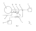
- a combustion system 1 comprises in its Air supply a blower 2 and two pressure sensors 3a, 3b upstream of a Fuel nozzle 4, with the interposition of a valve 5 via a fuel source. 6 is dinable. Downstream of the fuel nozzle 4 is an igniter and not shown Finally, a burner output 7 for discharging heat to a non-illustrated Cooking chamber arranged.
- the pressure measuring sensors 3a, 3b and the valve 5 are provided with a Control device 8 connected, the controlled variables 9, for example, not one Garprozeßprocessler shown, as in the unpublished DE 199 45 021 is described, can be supplied while the control device 8 is a manipulated variable 10 to the Blower 2 outputs and causes the opening and closing of the valve 5.
- the combustion system 1 shown in FIG. 2 does not differ fundamentally from that according to FIG. 1, so that the same parts are identified by the same reference numerals. It is especially important to note that in the embodiment of FIG. 2 in the area a constriction 11 in the air supply via the pressure measuring 3a, 3b a dynamic Negative pressure is detectable, resulting from the product of the air density, which depends on respective pressure, the sea level, the humidity and the composition of the supplied Air is, and the square gives the air speed.
- the combustion system 1 enables a regulated heat release the cooking chamber, which is arranged downstream of the burner outlet 7.
- the valve 5 open as a function of the measurement result of the pressure measuring sensors 3a, 3b via the control device 8, so the output from the same manipulated variable 10, the speed the blower 2 and thus the air / fuel mixture downstream of the fuel nozzle. 4 and finally the deliverable amount of heat set.
- the control device 8 in the form of the controlled variable 9 for further Optimization of the heat emission to the cooking chamber depending on the cooking appliance state, GarprozeßTalk and / or Gargutschreib be set.
- valve 5 is open only when the Speed of the fan 2 has exceeded a predetermined value, as over the Pressure measuring sensors 3a, 3b detectable.
- GarprozeßSullivan and / or Gargutschreib of the control device 8 via a not shown heater means for introducing moisture, means for at least partially closing a drain from the oven and / or device for at least partially closing a trigger from the oven is adjustable.
Landscapes
- Engineering & Computer Science (AREA)
- Chemical & Material Sciences (AREA)
- Combustion & Propulsion (AREA)
- Mechanical Engineering (AREA)
- General Engineering & Computer Science (AREA)
- Life Sciences & Earth Sciences (AREA)
- Food Science & Technology (AREA)
- Regulation And Control Of Combustion (AREA)
Description
- Fig. 1
- ein Blockdiagramm eines erfindungsgemäßen Verbrennungssystems; und
- Fig. 2
- ein Blockdiagramm eines weiteren erfindungsgemäßen Verbrennungssystems.
Claims (9)
- Verbrennungssystem (1) für ein Gargerät, das eine Luftzufuhr mit einem Gebläse (2), eine über zumindest eine Düse (4) in die Luftzufuhr mündende Brennstoffzufuhr mit zumindest einem Ventil (5), eine Zündeinrichtung zum Zünden einer Luft/Brennstoff-Mischung stromabwärts-der Düse (4) und eine Steuer- und/oder Regeleinrichtung (8) zur Einstellung der Luft/Brennstoff-Mischung im Bereich der Zündeinrichtung umfaßt, dadurch gekennzeichnet, daß
die Steuer- und/oder Regeleinrichtung (8) zumindest ein einen Garprozeßzustand, einen Gargerätezustand und/oder einen Gargutzustand repräsentierendes erstes Gar-Signal (9) empfängt und/oder zumindest ein einen Garprozeßzustand, einen Gargerätezustand und/oder einen Gargutzustand einstellendes zweites Gar-Signal ausgibt, und die Steuer- und/oder Regeleinrichtung (8) die Luft/Brennstoff-Mischung über die Drehzahl des Gebläses (2) einstellt, wobei die Menge an Brennstoff durch Dimensionierung der Austrittsöffnung der Düse (4) sowie die Einstellung des Ventils (5) auf die Nennbelastung des Verbrennungssystems (1) einmalig abstimmbar ist. - Verbrennungssystem nach Anspruch 1, dadurch gekennzeichnet, daß
die Steuer- und/oder Regeleinrichtung (8) in Abhängigkeit von der Einstellung des Ventils (5) in der Brennstoffzufuhr, zumindest einer, über eine Sensoreinrichtung (3a, 3b) erfaßbaren, vorzugsweise dynamischen, Luftgröße in der Luftzufuhr und/oder dem ersten Gar-Signal (9) die Drehzahl des Gebläses (2) verändert. - Verbrennungssystem nach Anspruch 1 oder 2, dadurch gekennzeichnet, daß
die Steuer- und/oder Regeleinrichtung (8) das Ventil (5) in der Brennstoffzufuhr in Abhängigkeit von dem ersten Gar-Signal (9) und/oder zumindest einer über eine Seusoreinrichtung (3a, 3b) erfaßbaren, vorzugsweise dynamischen, Luftgröße in der Luftzufuhr einstellt, wobei vorzugsweise beim Überschreiten eines ersten Wertes für die dynamische Luftgröße das Ventil zu öffnen und beim Unterschreiten eines zweiten Wertes für die dynamische Lufgröße das Ventil zu schließen ist. - Verbrennungssystem nach Anspruch 2 oder 3, dadurch gekennzeichnet, daß
die dynamische Luftgröße durch den Luftvolumenstrom, den Luftdurchfluß und/oder den Luftdruck, der im wesentlichen aus dem Quadrat der Luftgeschwindigkeit multipliziert mit der Luft- Rohdichte bestimmbar und insbesondere über eine Prallfläche oder eine Verengung (11) in der Luftzufuhr erfaßbar ist, dargestellt ist. - Verbrennungssystem nach einem der vorangehenden Ansprüche, dadurch gekennzeichnet, daß
das zweite Gar-Signal über die Drehzahl des Gebläses veränderbar ist. - Verbrennungssystem nach einem der vorangehenden Ansprüche, dadurch gekennzeichnet, daß
die Temperatur, die Feuchte und /oder die Umwälzrate im Garraum über das zweite Gar-Signal einstellbar ist bzw. sind. - Gargerät mit einem Garraum, einer Heizeinrichtung, einer Einrichtung zum Einführen von Feuchtigkeit in den Garraum, einem Ablauf aus dem Garraum, einem Abzug aus dem Garraum, einer Steuer- und/oder Regeleinheit für den Garablauf und einem Verbrennungssystem nach einem der vorangehenden Ansprüche.
- Gargerät nach Anspruch 7, dadurch gekennzeichnet, daß
die Steuer- und/oder Regeleinrichtung des Verbrennungssystems in einem mit der Steuer- und/oder Regeleinheit des Gargeräts ausgebildet ist. - Gargerät nach Anspruch 7 oder 8, dadurch gekennzeichnet, daß
die Steuer- und/oder Regeleinrichtung mit dem Gebläse, der Heizeinrichtung, der Einrichtung zum Einführen von Feuchtigkeit in den Garraum, einer Einrichtung zum zumindest teilweisen Verschließen des Ablaufs und/oder einer Einrichtung zum zumindest teilweise Verschließen des Abzugs verbunden ist.
Applications Claiming Priority (3)
| Application Number | Priority Date | Filing Date | Title |
|---|---|---|---|
| DE10037234 | 2000-07-31 | ||
| DE10037234A DE10037234A1 (de) | 2000-07-31 | 2000-07-31 | Verbrennungssystem für ein Gargerät sowie Gargerät mit solch einem Verbrennungssystem |
| PCT/DE2001/002531 WO2002010648A1 (de) | 2000-07-31 | 2001-07-05 | Verbrennungssystem für ein gargerät sowie gargerät mit solch einem verbrennungssystem |
Publications (2)
| Publication Number | Publication Date |
|---|---|
| EP1305553A1 EP1305553A1 (de) | 2003-05-02 |
| EP1305553B1 true EP1305553B1 (de) | 2004-09-29 |
Family
ID=7650816
Family Applications (1)
| Application Number | Title | Priority Date | Filing Date |
|---|---|---|---|
| EP01953873A Expired - Lifetime EP1305553B1 (de) | 2000-07-31 | 2001-07-05 | Verbrennungssystem für ein gargerät sowie gargerät mit solch einem verbrennungssystem |
Country Status (4)
| Country | Link |
|---|---|
| EP (1) | EP1305553B1 (de) |
| JP (1) | JP2004513317A (de) |
| DE (2) | DE10037234A1 (de) |
| WO (1) | WO2002010648A1 (de) |
Families Citing this family (5)
| Publication number | Priority date | Publication date | Assignee | Title |
|---|---|---|---|---|
| DE102004020365B3 (de) * | 2004-04-23 | 2005-12-01 | Rational Ag | Verfahren zur Einstellung der Leistung eines gasbetriebenen Gargerätes in Abhängigkeit von der geodätischen Höhe |
| EP2090827A3 (de) * | 2008-02-18 | 2017-09-27 | Honeywell Technologies Sarl | Regeleinrichtung für Gasbrenner |
| KR20140003558A (ko) * | 2011-01-21 | 2014-01-09 | 바브콕-히다찌 가부시끼가이샤 | 고체연료 버너 및 상기 버너를 이용하는 연소장치 |
| ITTO20130331A1 (it) * | 2013-04-23 | 2014-10-24 | Indesit Co Spa | Forno a gas ad alto rendimento e metodo per il suo funzionamento |
| DE102020121597A1 (de) * | 2020-08-18 | 2022-02-24 | Vaillant Gmbh | Verfahren und Anordnung zur pneumatischen Gemischbildung bei einem Vormischbrenner |
Family Cites Families (11)
| Publication number | Priority date | Publication date | Assignee | Title |
|---|---|---|---|---|
| US2820130A (en) * | 1955-04-08 | 1958-01-14 | American Motors Corp | Range |
| JPS5883128A (ja) * | 1981-11-12 | 1983-05-18 | Matsushita Electric Ind Co Ltd | 加熱調理器 |
| US4457291A (en) * | 1982-08-11 | 1984-07-03 | Lincoln Manufacturing Company, Inc. | Power burner system for a food preparation oven |
| DE3911268A1 (de) * | 1989-04-07 | 1990-10-11 | Honeywell Bv | Regeleinrichtung fuer gasbrenner |
| FR2650061B1 (fr) * | 1989-07-19 | 1991-11-15 | Gaz De France | Four perfectionne fonctionnant a la vapeur et/ou au gaz |
| DE4124742C2 (de) * | 1991-07-25 | 1994-06-09 | Eloma Gmbh | Gargerät, insbesondere für stückiges Gargut |
| JP3030137B2 (ja) * | 1991-09-13 | 2000-04-10 | パロマ工業株式会社 | ゆでめん機 |
| JP3293284B2 (ja) * | 1993-12-01 | 2002-06-17 | 松下電器産業株式会社 | 燃焼装置 |
| DE19718399A1 (de) * | 1997-04-30 | 1998-11-05 | Rational Gmbh | Verfahren zum individuellen Führen eines Garprozesses und zugehöriges Gargerät |
| DE19853262A1 (de) * | 1998-11-18 | 2000-05-25 | Bsh Bosch Siemens Hausgeraete | Regelung der Brennerheizleistung bei einem gasbetriebenen Koch- oder Backgerät |
| DE19945021C2 (de) | 1999-09-20 | 2003-10-23 | Rational Ag | Verfahren zum Steuern eines Garprozesses und hierzu verwendbare Garprozeßfühlereinrichtung |
-
2000
- 2000-07-31 DE DE10037234A patent/DE10037234A1/de not_active Ceased
-
2001
- 2001-07-05 DE DE50103900T patent/DE50103900D1/de not_active Expired - Lifetime
- 2001-07-05 EP EP01953873A patent/EP1305553B1/de not_active Expired - Lifetime
- 2001-07-05 JP JP2002516539A patent/JP2004513317A/ja active Pending
- 2001-07-05 WO PCT/DE2001/002531 patent/WO2002010648A1/de not_active Ceased
Also Published As
| Publication number | Publication date |
|---|---|
| EP1305553A1 (de) | 2003-05-02 |
| DE10037234A1 (de) | 2002-02-21 |
| WO2002010648A1 (de) | 2002-02-07 |
| JP2004513317A (ja) | 2004-04-30 |
| WO2002010648B1 (de) | 2003-10-02 |
| DE50103900D1 (de) | 2004-11-04 |
Similar Documents
| Publication | Publication Date | Title |
|---|---|---|
| EP3301362B1 (de) | Verfahren zur regelung turbulenter strömungen | |
| EP0644377B1 (de) | Regeleinrichtung für Gasbrenner | |
| DE69331081T2 (de) | Verfahren und Vorrichtung zum Mischen von Gasen | |
| DE3888327T2 (de) | Brennstoffbrennereinrichtung und ein Kontrollverfahren. | |
| DE3100267C2 (de) | Verfahren zur Optimierung des Betriebs einer viele Brenner aufweisenden natürlichen Zugverbrennungszone | |
| DE3010014A1 (de) | Vorrichtung zur einstellung des verbrennungsluftstromes bei brenngasverbrauchern | |
| DE3638410C2 (de) | ||
| EP3596391B1 (de) | Verfahren zur regelung eines brenngasbetriebenen heizgerätes | |
| EP1761728A1 (de) | Verfahren zur einstellung der luftzahl an einer feuerungseinrichtung und feuerungseinrichtung | |
| DE69210517T2 (de) | Nudelkochgerät | |
| DE69709928T2 (de) | Kombiniertes Regelsystem für Gas und Luft zur Verbrennungsregelung eines Gasheizkessels | |
| DE3232421C2 (de) | Schaltungsanordnung für eine wärmebedarfsabhängige Regelung der Heizleistung von Heizgeräten | |
| EP0505714B1 (de) | Regelvorrichtung für Gasbrenner mit einem Gebläse zum Zuführen von Verbrennungsluft | |
| DE1551993A1 (de) | Verfahren zum kontinuierlichen Regeln der Leistung von OEl- oder Gasbrennern und Vorrichtung zur Durchfuehrung dieses Verfahrens | |
| DE19510425C2 (de) | Verfahren und Vorrichtung zur Regelung eines Heizgerätes | |
| DE4334625B4 (de) | Verfahren zum Konstanthalten der Leistung eines Wassererwärmers | |
| DE19734574A1 (de) | Verfahren und Vorrichtung zum Regeln eines Brenners, insbesondere eines vormischenden Gasbrenners | |
| DE4312801A1 (de) | Verfahren zur Steuerung eines Gas-Gebläsebrenners | |
| EP1305553A1 (de) | Verbrennungssystem für ein gargerät sowie gargerät mit solch einem verbrennungssystem | |
| DE102004020365B3 (de) | Verfahren zur Einstellung der Leistung eines gasbetriebenen Gargerätes in Abhängigkeit von der geodätischen Höhe | |
| DE10220774B4 (de) | Einrichtung zur Regelung eines Brenners | |
| DE102020108198A1 (de) | Verfahren und Vorrichtung zur Verbesserung des Zündverhaltens eines Vormischbrenners | |
| EP3751200B1 (de) | Verfahren zur regelung eines brenngasbetriebenen heizgerätes | |
| DE2548494A1 (de) | Anlage zur regelung der temperatur in einem raum | |
| EP0857916B1 (de) | Verfahren zum Betrieb eines Steuer- und Regelgeräts für einen Brenner |
Legal Events
| Date | Code | Title | Description |
|---|---|---|---|
| PUAI | Public reference made under article 153(3) epc to a published international application that has entered the european phase |
Free format text: ORIGINAL CODE: 0009012 |
|
| 17P | Request for examination filed |
Effective date: 20021021 |
|
| AK | Designated contracting states |
Designated state(s): AT BE CH CY DE DK ES FI FR GB GR IE IT LI LU MC NL PT SE TR |
|
| AX | Request for extension of the european patent |
Extension state: AL LT LV MK RO SI |
|
| 17Q | First examination report despatched |
Effective date: 20030915 |
|
| GRAP | Despatch of communication of intention to grant a patent |
Free format text: ORIGINAL CODE: EPIDOSNIGR1 |
|
| RBV | Designated contracting states (corrected) |
Designated state(s): DE FR GB IT |
|
| GRAS | Grant fee paid |
Free format text: ORIGINAL CODE: EPIDOSNIGR3 |
|
| GRAA | (expected) grant |
Free format text: ORIGINAL CODE: 0009210 |
|
| AK | Designated contracting states |
Kind code of ref document: B1 Designated state(s): DE FR GB IT |
|
| REG | Reference to a national code |
Ref country code: GB Ref legal event code: FG4D Free format text: NOT ENGLISH |
|
| GBT | Gb: translation of ep patent filed (gb section 77(6)(a)/1977) | ||
| REG | Reference to a national code |
Ref country code: IE Ref legal event code: FG4D Free format text: GERMAN |
|
| REF | Corresponds to: |
Ref document number: 50103900 Country of ref document: DE Date of ref document: 20041104 Kind code of ref document: P |
|
| LTIE | Lt: invalidation of european patent or patent extension |
Effective date: 20040929 |
|
| REG | Reference to a national code |
Ref country code: IE Ref legal event code: FD4D |
|
| ET | Fr: translation filed | ||
| PLBE | No opposition filed within time limit |
Free format text: ORIGINAL CODE: 0009261 |
|
| STAA | Information on the status of an ep patent application or granted ep patent |
Free format text: STATUS: NO OPPOSITION FILED WITHIN TIME LIMIT |
|
| 26N | No opposition filed |
Effective date: 20050630 |
|
| PGFP | Annual fee paid to national office [announced via postgrant information from national office to epo] |
Ref country code: GB Payment date: 20080709 Year of fee payment: 8 |
|
| GBPC | Gb: european patent ceased through non-payment of renewal fee |
Effective date: 20090705 |
|
| PG25 | Lapsed in a contracting state [announced via postgrant information from national office to epo] |
Ref country code: GB Free format text: LAPSE BECAUSE OF NON-PAYMENT OF DUE FEES Effective date: 20090705 |
|
| PGFP | Annual fee paid to national office [announced via postgrant information from national office to epo] |
Ref country code: IT Payment date: 20130729 Year of fee payment: 13 |
|
| PG25 | Lapsed in a contracting state [announced via postgrant information from national office to epo] |
Ref country code: IT Free format text: LAPSE BECAUSE OF NON-PAYMENT OF DUE FEES Effective date: 20140705 |
|
| REG | Reference to a national code |
Ref country code: FR Ref legal event code: PLFP Year of fee payment: 16 |
|
| REG | Reference to a national code |
Ref country code: DE Ref legal event code: R084 Ref document number: 50103900 Country of ref document: DE |
|
| REG | Reference to a national code |
Ref country code: FR Ref legal event code: PLFP Year of fee payment: 17 |
|
| REG | Reference to a national code |
Ref country code: FR Ref legal event code: PLFP Year of fee payment: 18 |
|
| PGFP | Annual fee paid to national office [announced via postgrant information from national office to epo] |
Ref country code: TR Payment date: 20180731 Year of fee payment: 12 |
|
| PGFP | Annual fee paid to national office [announced via postgrant information from national office to epo] |
Ref country code: DE Payment date: 20190723 Year of fee payment: 19 |
|
| PG25 | Lapsed in a contracting state [announced via postgrant information from national office to epo] |
Ref country code: FR Free format text: LAPSE BECAUSE OF NON-PAYMENT OF DUE FEES Effective date: 20190731 |
|
| REG | Reference to a national code |
Ref country code: DE Ref legal event code: R119 Ref document number: 50103900 Country of ref document: DE |
|
| PG25 | Lapsed in a contracting state [announced via postgrant information from national office to epo] |
Ref country code: DE Free format text: LAPSE BECAUSE OF NON-PAYMENT OF DUE FEES Effective date: 20210202 |