EP1304772A2 - Kabelanschlussteil für eine Mittelspannungsschaltanlage - Google Patents
Kabelanschlussteil für eine Mittelspannungsschaltanlage Download PDFInfo
- Publication number
- EP1304772A2 EP1304772A2 EP02018192A EP02018192A EP1304772A2 EP 1304772 A2 EP1304772 A2 EP 1304772A2 EP 02018192 A EP02018192 A EP 02018192A EP 02018192 A EP02018192 A EP 02018192A EP 1304772 A2 EP1304772 A2 EP 1304772A2
- Authority
- EP
- European Patent Office
- Prior art keywords
- cable
- contact
- connection part
- cage
- cable connection
- Prior art date
- Legal status (The legal status is an assumption and is not a legal conclusion. Google has not performed a legal analysis and makes no representation as to the accuracy of the status listed.)
- Granted
Links
Images
Classifications
-
- H—ELECTRICITY
- H01—ELECTRIC ELEMENTS
- H01R—ELECTRICALLY-CONDUCTIVE CONNECTIONS; STRUCTURAL ASSOCIATIONS OF A PLURALITY OF MUTUALLY-INSULATED ELECTRICAL CONNECTING ELEMENTS; COUPLING DEVICES; CURRENT COLLECTORS
- H01R25/00—Coupling parts adapted for simultaneous co-operation with two or more identical counterparts, e.g. for distributing energy to two or more circuits
- H01R25/14—Rails or bus-bars constructed so that the counterparts can be connected thereto at any point along their length
- H01R25/142—Their counterparts
Definitions
- the invention relates to a cable connector for a medium voltage switchgear with which a conductor of the Medium voltage switchgear connected with a cable can be.
- Such cable connection parts are known Medium voltage switchgear with the help of Realized screw connections. This represents one considerable assembly effort. Also bring such Screw connections usually a considerable one Isolation effort with itself. So are at Medium voltage switchgear is often complex Phase partitions or the like for the isolation of such Known cable connection parts required.
- the object of the invention is to provide a cable connector create less assembly effort and less Isolation effort required.
- This task is performed with a cable connector initially mentioned type according to the invention solved in that a contact system is provided in the Inner cable of the cable can be inserted, and in which Cable can be fixed in the radial and in the axial direction.
- the invention therefore no longer sees screw connections in front. Instead, a contact system according to the invention in which the inner cable of the with the conductor cable to be connected can be inserted.
- the contact system is designed such that the cable in a radial and is fixed in the axial direction.
- the contact system has a contact part with it Contact springs on, with a contact cage on the free End of the inner cable can be plugged in and where Inner cable with the contact cage between the Contact springs of the contact system can be inserted.
- the contact cage thus forms one with the contact springs Connection with which the radial and axial fixation of the inner cable within the contact system becomes.
- the contact cage has an outwardly projecting part. This part occurs then in active contact with the contact springs, that in particular the axial fixation of the Inner cable inside the contact system is improved.
- the contact cage has a plurality of segments that start with Are held together by a circumferential spring can and can be plugged onto the inner cable.
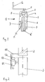
- 1 shows a cable connecting part 1, with which a conductor L can be connected to a cable K. can.
- the cable connector 1 is essentially rotationally symmetrical.
- the cable connector 1 has a fixed contact 2, which is fixed to the conductor L. connected, for example welded. With the Fixed contact 2, a contact system 3 is firmly connected be explained in more detail in connection with Figure 2 becomes.
- the fixed contact 2 and the contact system 3 are in one Insulated body 4 cast.
- the insulating body can for example made of silicone or EPDM (ethylene-propylene sealing material) consist.
- the insulating body 4 is pot-shaped, which in Figure 1 with the help of dashed line should be indicated.
- the cable K can be inserted.
- the cable K consists of an inner cable 5, a main insulation 6 arranged above it and one again cable insulation 7 arranged above it.
- a several potential controls 8 In or on the insulating body 4 are still a several potential controls 8 and one or more capacitive conductive pads 9 or cast. Above or About the capacitive pads 9 that Cable connector 1 via a capacitance to earth be switched. In terms of capacity, one can Voltage test system or a voltage display system be connected.
- the cable connection part 1 can be designed with multiple poles. In In this case, several, in particular up to four, cables can be used be available per phase.
- the contact system 3 is shown in more detail in FIG shown.
- the contact system 3 thus has a contact part 10, which is firmly connected to the fixed contact 2, for example is welded.
- the contact part 10 is Pot-shaped and consists of an electric conductive material.
- the contact springs 11 are In the interior of the contact part 10, namely on the circumferential inner wall of the contact part 10, are Contact springs 11 arranged. There are a majority such contact springs 11 along the circumference of the Contact part 10.
- the contact springs 11 are made of one made of electrically conductive material.
- the Contact springs 11 can be fixed to the contact part 10 connected, in particular welded.
- the inner cable 5 is enlarged shown.
- an annular contact cage 12 is attached on the free end of the inner cable 5 .
- the Inner diameter of the contact cage 12 corresponds to Essentially the outer diameter of the inner cable 5.
- the outer diameter of the contact cage 12 is on the Inner diameter of the contact part 10 and in particular the inner diameter of the contact springs 11 adjusted.
- the Contact cage 12 can consist of a plurality of segments be composed. In this case, the segments of the contact cage 12 with the help of a circumferential, annular spring 13 held together.
- the contact cage 12 or its segments and, if present, the spring 13 are electrically made of conductive material.
- the cable insulation 7 removed from the cable K.
- the Removal of the cable insulation 7 is such made that the cable insulation 7 in the interior of the insulating body 4 extends when the cable K in the Insulator 4 is introduced. Furthermore, the Main insulation 6 of the cable K removed so that the Inner cable 5 inserted into the contact system 3 or can be inserted.
- the contact cage 12 is then, if necessary, assisted the spring 13 on the free end of the inner cable 5 attached.
- the inner cable 5 together with the plugged contact cage 12 is then in the interior of the insulating body 4 introduced. Finally the Inner cable 5 with the attached contact cage 12 in introduced the interior of the contact part 10 and between the springs 11 are inserted into the contact system 3.
- the electrically conductive components 2, 10, 11, 12 and 13 possibly creates a conductive connection between the Conductor L and the inner cable 5 of the cable K.
- the springs 11 of the contact system 3 is the inner cable 5 within the contact system 3 and thus within the Cable connector 1 fixed in the radial direction.
- the contact cage 12 in cross section has an L-shaped design. In this case the outwardly projecting part of the contact cage 12 a further fixation of the contact inner conductor 5 within the Contact system 3 in the axial direction.
- the contact cage 12 can also be provided Differences in the outer diameter of the inner cable 5 and the inner diameter of the contact springs 11 compensate. On the one hand, it is possible to change the width of the contact cage 12 in the radial direction to the Adjust the outer diameter of the inner cable 5.
- the contact cage 12 consists of a plurality of Segments, such an adjustment can be made by a different number of segments and their attachment on the free end of the inner cable 5 using the Spring 13 are made.
- Another measure for fixing the cable K within the interior of the cable connector 1 can be inside exist, for example annular Insulation spacers on the main insulation 6 and / or put on the cable insulation 7, the outside diameter essentially with the inner diameter of the insulating body 4 matches.
- the cable connection part 1 described is designed such that that it is for a rated operational current, a Short circuit current and a surge short circuit current up to the Values of 2500 A, 50 kA (3 s) and 125 kA can be used can.
- the cable connection part 1 is preferred for connecting a circuit breaker one Medium voltage switchgear with a medium voltage cable suitable.
- the tension in such a Medium voltage switchgear is usually larger than 1 kilovolt and less than or equal to 52 kilovolts.
Landscapes
- Cable Accessories (AREA)
- Coupling Device And Connection With Printed Circuit (AREA)
- Gas-Insulated Switchgears (AREA)
- Communication Cables (AREA)
- Suspension Of Electric Lines Or Cables (AREA)
Abstract
Description
- Figur 1
- zeigt einen schematischen Querschnitt eines Ausführungsbeispiels eines erfindungsgemäßen Kabelanschlussteils; und
- Figur 2
- zeigt einen schematischen Querschnitt eines Kontaktsystems des Kabelanschlussteils der Figur 1.
Claims (9)
- Kabelanschlussteil (1) für eine Mittelspannungsschaltanlage, mit dem ein Leiter (L) der Mittelspannungsschaltanlage mit einem Kabel (K) verbunden werden kann, dadurch gekennzeichnet, daß ein Kontaktsystem (3) vorgesehen ist, in das ein Kabelinnenleiter (5) des Kabels (K) einsteckbar ist, und in dem das Kabel (K) in radialer und in axialer Richtung fixierbar ist.
- Kabelanschlussteil (1) nach Anspruch 1, dadurch gekennzeichnet, daß das Kontaktsystem (3) ein Kontaktteil (10) mit darin befindlichen Kontaktfedern (11) aufweist, daß ein Kontaktkäfig (12) auf das freie Ende des Kabelinnenleiters (5) aufsteckbar ist, und daß der Kabelinnenleiter (5) mit dem Kontaktkäfig (12) zwischen die Kontaktfedern (11) des Kontaktsystems (3) einsteckbar ist.
- Kabelanschlussteil (1) nach Anspruch 2, dadurch gekennzeichnet, daß eine Mehrzahl von Kontaktfedern (11) am Umfang der Innenwand des topförmig ausgebildeten Kontaktteils (10) angeordnet sind.
- Kabelanschlussteil (1) nach einem der Ansprüche 2 oder 3, dadurch gekennzeichnet, daß der Kontaktkäfig (12) eine Mehrzahl von Segmenten aufweist, die mit Hilfe einer umlaufenden Feder (13) zusammengehalten werden können und damit auf den Kabelinnenleiter (5) aufsteckbar sind.
- Kabelanschlussteil (1) nach einem der Ansprüche 2 bis 4, dadurch gekennzeichnet, daß der Kontaktkäfig (12) ein nach außen abstehendes Teil aufweist.
- Kabelanschlussteil (1) nach einem der vorstehenden Ansprüche, dadurch gekennzeichnet, daß ein Isolierkörper (4) vorgesehen ist, in dem das Kontaktsystem (3) untergebracht ist, und der das in das Kontaktsystem (3) eingesteckte Kabel (K) umgibt.
- Kabelanschlussteil (1) nach Anspruch 6, dadurch gekennzeichnet, daß der Isolierkörper (4) mit einer Potentialsteuerung (8) und/oder einem kapazitiven Leitbelag (9) versehen ist.
- Kabelanschlussteil (1) nach einem der vorstehenden Ansprüche, dadurch gekennzeichnet, daß die stromführenden Bauteile auf einen Bemessungsbetriebsstrom von 2500 A, einen Kurzschlußstrom von 50 kA bei 3 Sekunden und einen Stoßkurzschlußstrom von 125 kA ausgelegt sind.
- Mittelspannungsschaltanlage, gekennzeichnet durch ein Kabelanschlussteil (1) nach einem der vorstehenden Ansprüche.
Applications Claiming Priority (2)
| Application Number | Priority Date | Filing Date | Title |
|---|---|---|---|
| DE10151884A DE10151884A1 (de) | 2001-10-20 | 2001-10-20 | Kabelanschlussteil für eine Mittelspannungsschaltanlage |
| DE10151884 | 2001-10-20 |
Publications (3)
| Publication Number | Publication Date |
|---|---|
| EP1304772A2 true EP1304772A2 (de) | 2003-04-23 |
| EP1304772A3 EP1304772A3 (de) | 2004-01-02 |
| EP1304772B1 EP1304772B1 (de) | 2006-03-08 |
Family
ID=7703194
Family Applications (1)
| Application Number | Title | Priority Date | Filing Date |
|---|---|---|---|
| EP02018192A Expired - Lifetime EP1304772B1 (de) | 2001-10-20 | 2002-08-20 | Kabelanschlussteil für eine Mittelspannungsschaltanlage |
Country Status (5)
| Country | Link |
|---|---|
| EP (1) | EP1304772B1 (de) |
| AT (1) | ATE320093T1 (de) |
| DE (2) | DE10151884A1 (de) |
| ES (1) | ES2259060T3 (de) |
| PT (1) | PT1304772E (de) |
Family Cites Families (7)
| Publication number | Priority date | Publication date | Assignee | Title |
|---|---|---|---|---|
| DE2263060C3 (de) * | 1972-12-22 | 1975-12-11 | Kathrein-Werke Kg, 8200 Rosenheim | Spannhülsen |
| US3912352A (en) * | 1973-04-09 | 1975-10-14 | Joseph D Kinnear | Rotary electrical coupling |
| US3867602A (en) * | 1973-10-25 | 1975-02-18 | Mc Graw Edison Co | Contact cluster for arcing and current carrying means in a circuit breaker |
| DE3110660C2 (de) * | 1981-03-19 | 1983-07-14 | Karl Pfisterer Elektrotechnische Spezialartikel Gmbh & Co Kg, 7000 Stuttgart | Garnitur für das Ende eines Mittelspannnungs- oder Hochspannunskabels |
| DE3326386A1 (de) * | 1983-07-22 | 1985-01-31 | Kabel- Und Lackdrahtfabriken Gmbh, 6800 Mannheim | Vorgefertigter muffenkoerper |
| DE4135390C1 (en) * | 1991-10-26 | 1993-04-01 | Karl Pfisterer Elektrotechnische Spezialartikel Gmbh & Co Kg, 7000 Stuttgart, De | Current connecting plug for power supply - has rotatable fixing ring on housing allowing connection to housing of cooperating socket |
| FR2774814B1 (fr) * | 1998-02-09 | 2000-03-31 | Telecommunications Sa | Dispositif de connexion encliquetable pour extremite de cable electrique |
-
2001
- 2001-10-20 DE DE10151884A patent/DE10151884A1/de not_active Ceased
-
2002
- 2002-08-20 AT AT02018192T patent/ATE320093T1/de not_active IP Right Cessation
- 2002-08-20 EP EP02018192A patent/EP1304772B1/de not_active Expired - Lifetime
- 2002-08-20 DE DE50205992T patent/DE50205992D1/de not_active Expired - Lifetime
- 2002-08-20 ES ES02018192T patent/ES2259060T3/es not_active Expired - Lifetime
- 2002-08-20 PT PT02018192T patent/PT1304772E/pt unknown
Also Published As
| Publication number | Publication date |
|---|---|
| EP1304772A3 (de) | 2004-01-02 |
| EP1304772B1 (de) | 2006-03-08 |
| ES2259060T3 (es) | 2006-09-16 |
| PT1304772E (pt) | 2006-05-31 |
| DE50205992D1 (de) | 2006-05-04 |
| DE10151884A1 (de) | 2003-04-30 |
| ATE320093T1 (de) | 2006-03-15 |
Similar Documents
| Publication | Publication Date | Title |
|---|---|---|
| DE69207238T2 (de) | Verbindungsvorrichtung für ein oder zwei elektrische Kabel, und Verfahren zum Montieren der Vorrichtung an das Ende des oder der Kabel | |
| DE69704866T2 (de) | Elektrischer verbinder | |
| DE4424072C1 (de) | Steckendverschluß | |
| DE2614085A1 (de) | Kabelverbindung | |
| EP0060930A1 (de) | Garnitur für das Ende eines Mittelspannungs- oder Hochspannungskabels | |
| CH635708A5 (de) | Kabelendverschluss an einem hochspannungskabel. | |
| EP1876682B1 (de) | Kabelsteckverbinder einer Steckverbindungseinrichtung für die Mittel- und Hochspannungstechnik | |
| EP1304772B1 (de) | Kabelanschlussteil für eine Mittelspannungsschaltanlage | |
| EP0773601A2 (de) | Sicherheitssteckverbindung | |
| DE3438299A1 (de) | Schutzgehaeuse fuer winkelstecker kunststoffisolierter mittelspannungskabel | |
| EP3699934A1 (de) | Elektrische durchführung für ein druckgehäuse | |
| DE102018201160A1 (de) | Hochspannungsdurchführung, elektrisches Gerät mit Hochspannungsdurchführung und Verfahren zur Herstellung des elektrischen Gerätes | |
| DE2410625A1 (de) | Hochspannungs-verbindungsvorrichtung | |
| DE102024125576B3 (de) | Steckeinrichtung | |
| DE4135390C1 (en) | Current connecting plug for power supply - has rotatable fixing ring on housing allowing connection to housing of cooperating socket | |
| DE3224743C2 (de) | ||
| EP4070417B1 (de) | Elektrische koppelvorrichtung, elektrisches system und verfahren zum elektrischen sowie mechanischen koppeln | |
| DE2942769A1 (de) | Trennschalter | |
| EP0736943B1 (de) | Vorrichtung zur Verbindung zweier Kabelenden | |
| DE3743268C2 (de) | ||
| EP3400603B1 (de) | Wicklungsanordnung mit steckdurchführung | |
| DE29813879U1 (de) | Elektrischer Anschlußstecker mit zweiteiliger Überwurfmutter | |
| EP0798757A2 (de) | Sicherungsanschlusseinrichtung für kompakte Netzstationen | |
| WO1998047206A1 (de) | Spannungswandler | |
| WO2006084401A1 (de) | Schalterpol |
Legal Events
| Date | Code | Title | Description |
|---|---|---|---|
| PUAI | Public reference made under article 153(3) epc to a published international application that has entered the european phase |
Free format text: ORIGINAL CODE: 0009012 |
|
| AK | Designated contracting states |
Designated state(s): AT BE BG CH CY CZ DE DK EE ES FI FR GB GR IE IT LI LU MC NL PT SE SK TR |
|
| AX | Request for extension of the european patent |
Extension state: AL LT LV MK RO SI |
|
| PUAL | Search report despatched |
Free format text: ORIGINAL CODE: 0009013 |
|
| AK | Designated contracting states |
Kind code of ref document: A3 Designated state(s): AT BE BG CH CY CZ DE DK EE ES FI FR GB GR IE IT LI LU MC NL PT SE SK TR |
|
| AX | Request for extension of the european patent |
Extension state: AL LT LV MK RO SI |
|
| RIC1 | Information provided on ipc code assigned before grant |
Ipc: 7H 01R 13/53 B Ipc: 7H 01R 13/187 A |
|
| 17P | Request for examination filed |
Effective date: 20040225 |
|
| 17Q | First examination report despatched |
Effective date: 20040415 |
|
| AKX | Designation fees paid |
Designated state(s): AT BE BG CH CY CZ DE DK EE ES FI FR GB GR IE IT LI LU MC NL PT SE SK TR |
|
| GRAP | Despatch of communication of intention to grant a patent |
Free format text: ORIGINAL CODE: EPIDOSNIGR1 |
|
| GRAS | Grant fee paid |
Free format text: ORIGINAL CODE: EPIDOSNIGR3 |
|
| GRAA | (expected) grant |
Free format text: ORIGINAL CODE: 0009210 |
|
| AK | Designated contracting states |
Kind code of ref document: B1 Designated state(s): AT BE BG CH CY CZ DE DK EE ES FI FR GB GR IE IT LI LU MC NL PT SE SK TR |
|
| PG25 | Lapsed in a contracting state [announced via postgrant information from national office to epo] |
Ref country code: SK Free format text: LAPSE BECAUSE OF FAILURE TO SUBMIT A TRANSLATION OF THE DESCRIPTION OR TO PAY THE FEE WITHIN THE PRESCRIBED TIME-LIMIT Effective date: 20060308 Ref country code: FI Free format text: LAPSE BECAUSE OF FAILURE TO SUBMIT A TRANSLATION OF THE DESCRIPTION OR TO PAY THE FEE WITHIN THE PRESCRIBED TIME-LIMIT Effective date: 20060308 Ref country code: IE Free format text: LAPSE BECAUSE OF FAILURE TO SUBMIT A TRANSLATION OF THE DESCRIPTION OR TO PAY THE FEE WITHIN THE PRESCRIBED TIME-LIMIT Effective date: 20060308 |
|
| REG | Reference to a national code |
Ref country code: GB Ref legal event code: FG4D Free format text: NOT ENGLISH |
|
| REG | Reference to a national code |
Ref country code: CH Ref legal event code: EP |
|
| RAP2 | Party data changed (patent owner data changed or rights of a patent transferred) |
Owner name: AREVA T&D SA |
|
| REG | Reference to a national code |
Ref country code: IE Ref legal event code: FG4D Free format text: LANGUAGE OF EP DOCUMENT: GERMAN |
|
| GBT | Gb: translation of ep patent filed (gb section 77(6)(a)/1977) |
Effective date: 20060327 |
|
| REF | Corresponds to: |
Ref document number: 50205992 Country of ref document: DE Date of ref document: 20060504 Kind code of ref document: P |
|
| REG | Reference to a national code |
Ref country code: PT Ref legal event code: SC4A Effective date: 20060330 Ref country code: CH Ref legal event code: NV Representative=s name: MICHELI & CIE INGENIEURS-CONSEILS |
|
| NLT2 | Nl: modifications (of names), taken from the european patent patent bulletin |
Owner name: AREVA T&D SA Effective date: 20060322 |
|
| PG25 | Lapsed in a contracting state [announced via postgrant information from national office to epo] |
Ref country code: DK Free format text: LAPSE BECAUSE OF FAILURE TO SUBMIT A TRANSLATION OF THE DESCRIPTION OR TO PAY THE FEE WITHIN THE PRESCRIBED TIME-LIMIT Effective date: 20060608 Ref country code: BG Free format text: LAPSE BECAUSE OF FAILURE TO SUBMIT A TRANSLATION OF THE DESCRIPTION OR TO PAY THE FEE WITHIN THE PRESCRIBED TIME-LIMIT Effective date: 20060608 |
|
| REG | Reference to a national code |
Ref country code: SE Ref legal event code: TRGR |
|
| PG25 | Lapsed in a contracting state [announced via postgrant information from national office to epo] |
Ref country code: MC Free format text: LAPSE BECAUSE OF NON-PAYMENT OF DUE FEES Effective date: 20060831 |
|
| REG | Reference to a national code |
Ref country code: ES Ref legal event code: FG2A Ref document number: 2259060 Country of ref document: ES Kind code of ref document: T3 |
|
| ET | Fr: translation filed | ||
| REG | Reference to a national code |
Ref country code: IE Ref legal event code: FD4D |
|
| PLBE | No opposition filed within time limit |
Free format text: ORIGINAL CODE: 0009261 |
|
| STAA | Information on the status of an ep patent application or granted ep patent |
Free format text: STATUS: NO OPPOSITION FILED WITHIN TIME LIMIT |
|
| 26N | No opposition filed |
Effective date: 20061211 |
|
| PG25 | Lapsed in a contracting state [announced via postgrant information from national office to epo] |
Ref country code: GR Free format text: LAPSE BECAUSE OF FAILURE TO SUBMIT A TRANSLATION OF THE DESCRIPTION OR TO PAY THE FEE WITHIN THE PRESCRIBED TIME-LIMIT Effective date: 20060609 Ref country code: CZ Free format text: LAPSE BECAUSE OF FAILURE TO SUBMIT A TRANSLATION OF THE DESCRIPTION OR TO PAY THE FEE WITHIN THE PRESCRIBED TIME-LIMIT Effective date: 20060308 |
|
| PG25 | Lapsed in a contracting state [announced via postgrant information from national office to epo] |
Ref country code: EE Free format text: LAPSE BECAUSE OF FAILURE TO SUBMIT A TRANSLATION OF THE DESCRIPTION OR TO PAY THE FEE WITHIN THE PRESCRIBED TIME-LIMIT Effective date: 20060308 |
|
| PG25 | Lapsed in a contracting state [announced via postgrant information from national office to epo] |
Ref country code: TR Free format text: LAPSE BECAUSE OF FAILURE TO SUBMIT A TRANSLATION OF THE DESCRIPTION OR TO PAY THE FEE WITHIN THE PRESCRIBED TIME-LIMIT Effective date: 20060308 Ref country code: LU Free format text: LAPSE BECAUSE OF NON-PAYMENT OF DUE FEES Effective date: 20060820 |
|
| PG25 | Lapsed in a contracting state [announced via postgrant information from national office to epo] |
Ref country code: CY Free format text: LAPSE BECAUSE OF FAILURE TO SUBMIT A TRANSLATION OF THE DESCRIPTION OR TO PAY THE FEE WITHIN THE PRESCRIBED TIME-LIMIT Effective date: 20060308 |
|
| PGFP | Annual fee paid to national office [announced via postgrant information from national office to epo] |
Ref country code: AT Payment date: 20090820 Year of fee payment: 8 Ref country code: CH Payment date: 20090824 Year of fee payment: 8 Ref country code: NL Payment date: 20090820 Year of fee payment: 8 Ref country code: PT Payment date: 20090820 Year of fee payment: 8 |
|
| PGFP | Annual fee paid to national office [announced via postgrant information from national office to epo] |
Ref country code: BE Payment date: 20090821 Year of fee payment: 8 |
|
| PGFP | Annual fee paid to national office [announced via postgrant information from national office to epo] |
Ref country code: ES Payment date: 20100830 Year of fee payment: 9 |
|
| PGFP | Annual fee paid to national office [announced via postgrant information from national office to epo] |
Ref country code: FR Payment date: 20100901 Year of fee payment: 9 Ref country code: IT Payment date: 20100825 Year of fee payment: 9 Ref country code: SE Payment date: 20100823 Year of fee payment: 9 |
|
| PGFP | Annual fee paid to national office [announced via postgrant information from national office to epo] |
Ref country code: GB Payment date: 20100729 Year of fee payment: 9 |
|
| BERE | Be: lapsed |
Owner name: *ALSTOM Effective date: 20100831 |
|
| REG | Reference to a national code |
Ref country code: PT Ref legal event code: MM4A Free format text: LAPSE DUE TO NON-PAYMENT OF FEES Effective date: 20110221 |
|
| REG | Reference to a national code |
Ref country code: NL Ref legal event code: V1 Effective date: 20110301 |
|
| REG | Reference to a national code |
Ref country code: CH Ref legal event code: PL |
|
| PG25 | Lapsed in a contracting state [announced via postgrant information from national office to epo] |
Ref country code: CH Free format text: LAPSE BECAUSE OF NON-PAYMENT OF DUE FEES Effective date: 20100831 Ref country code: LI Free format text: LAPSE BECAUSE OF NON-PAYMENT OF DUE FEES Effective date: 20100831 |
|
| PG25 | Lapsed in a contracting state [announced via postgrant information from national office to epo] |
Ref country code: PT Free format text: LAPSE BECAUSE OF NON-PAYMENT OF DUE FEES Effective date: 20110221 Ref country code: AT Free format text: LAPSE BECAUSE OF NON-PAYMENT OF DUE FEES Effective date: 20100820 Ref country code: NL Free format text: LAPSE BECAUSE OF NON-PAYMENT OF DUE FEES Effective date: 20110301 |
|
| PG25 | Lapsed in a contracting state [announced via postgrant information from national office to epo] |
Ref country code: BE Free format text: LAPSE BECAUSE OF NON-PAYMENT OF DUE FEES Effective date: 20100831 |
|
| REG | Reference to a national code |
Ref country code: DE Ref legal event code: R084 Ref document number: 50205992 Country of ref document: DE Effective date: 20110728 |
|
| REG | Reference to a national code |
Ref country code: DE Ref legal event code: R082 Ref document number: 50205992 Country of ref document: DE Representative=s name: DREISS PATENTANWAELTE, DE |
|
| REG | Reference to a national code |
Ref country code: DE Ref legal event code: R081 Ref document number: 50205992 Country of ref document: DE Owner name: SCHNEIDER ELECTRIC ENERGY FRANCE, FR Free format text: FORMER OWNER: AREVA T&D SA, PARIS, FR Effective date: 20120116 Ref country code: DE Ref legal event code: R082 Ref document number: 50205992 Country of ref document: DE Representative=s name: DREISS PATENTANWAELTE PARTG MBB, DE Effective date: 20120116 |
|
| REG | Reference to a national code |
Ref country code: SE Ref legal event code: EUG |
|
| GBPC | Gb: european patent ceased through non-payment of renewal fee |
Effective date: 20110820 |
|
| REG | Reference to a national code |
Ref country code: FR Ref legal event code: ST Effective date: 20120430 |
|
| PG25 | Lapsed in a contracting state [announced via postgrant information from national office to epo] |
Ref country code: IT Free format text: LAPSE BECAUSE OF NON-PAYMENT OF DUE FEES Effective date: 20110820 |
|
| PG25 | Lapsed in a contracting state [announced via postgrant information from national office to epo] |
Ref country code: GB Free format text: LAPSE BECAUSE OF NON-PAYMENT OF DUE FEES Effective date: 20110820 Ref country code: FR Free format text: LAPSE BECAUSE OF NON-PAYMENT OF DUE FEES Effective date: 20110831 |
|
| PG25 | Lapsed in a contracting state [announced via postgrant information from national office to epo] |
Ref country code: SE Free format text: LAPSE BECAUSE OF NON-PAYMENT OF DUE FEES Effective date: 20110821 |
|
| REG | Reference to a national code |
Ref country code: ES Ref legal event code: FD2A Effective date: 20130605 |
|
| PG25 | Lapsed in a contracting state [announced via postgrant information from national office to epo] |
Ref country code: ES Free format text: LAPSE BECAUSE OF NON-PAYMENT OF DUE FEES Effective date: 20110821 |
|
| PGFP | Annual fee paid to national office [announced via postgrant information from national office to epo] |
Ref country code: DE Payment date: 20160701 Year of fee payment: 15 |
|
| REG | Reference to a national code |
Ref country code: DE Ref legal event code: R119 Ref document number: 50205992 Country of ref document: DE |
|
| PG25 | Lapsed in a contracting state [announced via postgrant information from national office to epo] |
Ref country code: DE Free format text: LAPSE BECAUSE OF NON-PAYMENT OF DUE FEES Effective date: 20180301 |