EP1304441A2 - Schiessfolgeregler - Google Patents
Schiessfolgeregler Download PDFInfo
- Publication number
- EP1304441A2 EP1304441A2 EP02023356A EP02023356A EP1304441A2 EP 1304441 A2 EP1304441 A2 EP 1304441A2 EP 02023356 A EP02023356 A EP 02023356A EP 02023356 A EP02023356 A EP 02023356A EP 1304441 A2 EP1304441 A2 EP 1304441A2
- Authority
- EP
- European Patent Office
- Prior art keywords
- leaf
- slide
- sequence controller
- controller according
- locking
- Prior art date
- Legal status (The legal status is an assumption and is not a legal conclusion. Google has not performed a legal analysis and makes no representation as to the accuracy of the status listed.)
- Withdrawn
Links
Images

Classifications
-
- E—FIXED CONSTRUCTIONS
- E05—LOCKS; KEYS; WINDOW OR DOOR FITTINGS; SAFES
- E05F—DEVICES FOR MOVING WINGS INTO OPEN OR CLOSED POSITION; CHECKS FOR WINGS; WING FITTINGS NOT OTHERWISE PROVIDED FOR, CONCERNED WITH THE FUNCTIONING OF THE WING
- E05F5/00—Braking devices, e.g. checks; Stops; Buffers
- E05F5/12—Braking devices, e.g. checks; Stops; Buffers specially for preventing the closing of a wing before another wing has been closed
-
- E—FIXED CONSTRUCTIONS
- E05—LOCKS; KEYS; WINDOW OR DOOR FITTINGS; SAFES
- E05Y—INDEXING SCHEME ASSOCIATED WITH SUBCLASSES E05D AND E05F, RELATING TO CONSTRUCTION ELEMENTS, ELECTRIC CONTROL, POWER SUPPLY, POWER SIGNAL OR TRANSMISSION, USER INTERFACES, MOUNTING OR COUPLING, DETAILS, ACCESSORIES, AUXILIARY OPERATIONS NOT OTHERWISE PROVIDED FOR, APPLICATION THEREOF
- E05Y2900/00—Application of doors, windows, wings or fittings thereof
- E05Y2900/10—Application of doors, windows, wings or fittings thereof for buildings or parts thereof
- E05Y2900/13—Type of wing
- E05Y2900/132—Doors
Definitions
- the invention relates to a closing sequence controller for a self-closing, a door comprising a passive leaf and a active leaf, the active leaf lockable by means of a locking mechanism that can be released from the passive leaf and where the passive leaf and the active leaf each have a swivel arm have that with its door frame side end with one in a sliding guide preferably attached to the door frame Provide the guided passive leaf slide or active leaf slide is.
- closing sequence controllers are used, which are always the ones for the aforementioned proper closing required order ensure the transitions of the two door leaves into the closed position.
- a certain order of closing movement of both door leaves is also therefore necessary to get the usually with a lock Only let the active leaf reach the closed position when the forming the door stop, usually the striking plate or the like having standing leaf is closed.
- a closing sequence controller for a self-closing, known a door comprising a fixed and a moving wing, whose door leaves are each connected to the door frame via a swivel arm are, the swivel arm of the active leaf by means of one of the passive leaf releasable locking member can be determined.
- the passive leaf works with you axially adjustable pusher together, to release the finding of the slider acts on the locking member.
- Such a closing sequence controller is z. B. become known from DE 40 38 720 A1.
- the object of the present invention is therefore the above eliminate the disadvantages mentioned and a mechanical Closing sequence controller to create a secured closing sequence of a door guaranteed, but with as few and also simply constructed Components reached and also in a small, narrow sliding guide can be retrofitted.
- the structure is simple and simple Components provided a closing sequence controller, which is a secured Guaranteed closing sequence.
- the construction also has the advantage that the entire closing sequence controller is very compact and can therefore be easily and conveniently installed and removed, e.g. B. at a repair or for maintenance purposes or in existing sliding guides. Since it consists of only a few and relatively small individual parts not just the storage of the entire closing sequence controller, but the provision of individual or spare parts is simple and uncomplicated and takes up little space.
- the closing sequence controller according to the present invention because of its light weight can also be easily installed or removed.
- FIGS. 1 and 2 the structure and operation of a Closing sequence controller according to a preferred embodiment of the present Invention shown.
- This closing sequence controller is particularly suitable for a door with one active leaf and one passive leaf each connected to the door frame via a swivel arm, not shown are.
- the door frame end of the swivel arm is Inactive leaf with a sliding guide attached to the door frame 1 slidably guided leaf slide 2.
- the active leaf, the passive leaf, the door frame and the two swivel arms are general state of the art and are therefore not described in more detail here shown or explained.
- the closing sequence controller comprises the slide guide 1, in which the fixed leaf slide 2 and the active leaf slide 3 in the longitudinal direction of the sliding guide 1 are guided.
- the Slideway 1 divided into two chamber areas 10, 11.
- the passive leaf slider 2 In the lower one Chamber area 10 in Figures 1 and 2 become the passive leaf slider 2 and the active leaf slider 3 can be moved along the sliding guide 1 stored.
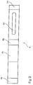
- Lock sequence controller housed in the upper chamber region 11 Lock sequence controller housed. This is particularly by a Slider 4, which can also be moved in the longitudinal direction of the sliding guide 1 is stored and under the effect of a preferably as a coil spring 6 trained spring is formed.
- the slider 4 has a projecting edge 4a at one end on, which protrudes into the chamber area 10 and over which the passive leaf slider 2 act on the slider 4 and can control it.
- the Coil spring 6 acts on the opposite of the projecting edge 4a Side of the slider 4 on this and pushes the slider 4 in Direction to the fixed leaf slide 2.
- the slide 4 is still with provided a stop 4b, on which a recessed on one side Area 4c joins, which is in the direction of the projecting Edge 4a extends.
- On the other side of the stop 4a an elongated hole 4d is provided which extends in the longitudinal direction of the slide 4 in Direction extends to the coil spring 6.
- An adjusting device is arranged in the elongated hole 4d. This exists from a screw 7 which passes through the elongated hole 4d and with one End can be clamped in the slide guide 1 in the chamber region 11 is, e.g. B. via a centering point arranged at this end (cf. figures 1 and 2).
- the other end of the screw 7 carries a receptacle 8 for a preferably designed as a leaf spring 9, which is on its front End carries a latch 5.
- the latch 5 is depending on the position of the slide 4 by the stop 4b supports and thus held in its position or can under the influence of external forces, due to the elasticity of the leaf spring 9, shift towards the slider 4, being in the recessed Immersed area 4c.
- the latch 5 has two in the direction of movement the slider 4 into the chamber region 10 inclined Surfaces that are preferably inclined at different angles are.
- the latch 5, which connected to the screw 7 via the leaf spring 9 and the receptacle 8 is fixed in the slide guide 1 at a certain position, which is selected depending on the width of the door. Since the screw 7 that Passes through slot 4d of the slider 4, the slider 4 can thus corresponding to the extent of the elongated hole 4d in the sliding guide 1 and move around. However, it is in through the coil spring 6 in Direction pressed on the fixed leaf slide 2.
- the active leaf should also be closed again the process explained above runs in reverse Order.
- the active leaf slide 3 runs on the right oblique Surface 13 of the pawl 5, pushes it up again in the recessed Area 4c and then slides over the latch 5 further to the left in its end position, while the pawl 5 in again their rest position shown in Figure 1 returns. So when closed Inactive leaf of the active leaf opened and closed as required become.
- the passive leaf slide 2 moves to the left in Figure 2. Due to the preload of the coil spring 6, the slide 4 follows the active leaf slide 3 until it has the right limit of the elongated hole 4d abuts the screw 7 (see FIG. 2) or the Recording 8 of the screw 7 in front of a projection 14, which at the end of the slide 4 is present, which is acted upon by the spring 6 for Facility is coming. In this position, the stop 4b is below the pawl 5 and thus prevents movement of the pawl 5 in Direction on the slide 4. The latch 5 can in this position do not move back into the recessed area 4c.
- the angle at which the two inclined surfaces 12, 13 of the latch 5 are inclined preferably on the right side in Figure 1, i.e. H. be larger on the side that blocks the active leaf slide 3 than on the left.
Landscapes
- Closing And Opening Devices For Wings, And Checks For Wings (AREA)
- Specific Sealing Or Ventilating Devices For Doors And Windows (AREA)
- Power-Operated Mechanisms For Wings (AREA)
Abstract
- Das Standflügel-Gleitstück (2) steuert einen Schieber (4), der den Sperrmechanismus freigibt bzw. blockiert.
- Der Sperrmechanismus besteht aus einer Rastklinke (5), die im freigegebenen Zustand senkrecht zur Bewegungsrichtung des Schiebers (4) von dem Gangflügel-Gleitstück (3) verschiebbar ist und im blockierten Zustand eine Bewegung des Gangflügel-Gleitstückes (3) stoppt.
Description
- Das Standflügel-Gleitstück steuert einen Schieber, der den Sperrmechanismus freigibt bzw. blockiert.
- Der Sperrmechanismus besteht aus einer Rastklinke, die im freigegebenen Zustand senkrecht zur Bewegungsrichtung des Schiebers von dem Gangflügel-Gleitstück verschiebbar ist und im blockierten Zustand eine Bewegung des Gangflügel-Gleitstückes stoppt.
- Figur 1:
- Den Aufbau eines erfindungsgemäßen Schließfolgereglers bei geschlossenem Standflügel,
- Figur 2:
- den Aufbau des erfindungsgemäßen Schließfolgereglers bei geöffnetem Standflügel und
- Figur 3:
- eine Ansicht eines im erfindungsgemäßen Schließfolgeregler verwendeten Schiebers.
- 1
- Gleitführung
- 2
- Standflügel-Gleitstück
- 3
- Gangflügel-Gleitstück
- 4
- Schieber
- 4a
- vorspringende Kante
- 4b
- Anschlag
- 4c
- zurückspringender Bereich
- 4d
- Langloch
- 5
- Rastklinke
- 6
- Schraubenfeder
- 7
- Schraube
- 8
- Aufnahme
- 9
- Blattfeder
- 10
- Kammerbereich
- 11
- Kammerbereich
- 12
- geneigte Fläche
- 13
- geneigte Fläche
- 14
- Vorsprung
Claims (11)
- Schließfolgeregler für eine selbstschließende, einen Stand- und einen Gangflügel umfassende Tür, wobei der Gangflügel mittels eines vom Standflügel freigebbaren Sperrmechanismus feststellbar ist und wobei der Standflügel und der Gangflügel jeweils einen Schwenkarm aufweisen, der mit seinem türrahmenseitigen Ende mit je einem in einer am Türrahmen angebrachten Gleitführung verschiebbar geführten Standflügel-Gleitstück bzw. Gangflügel-Gleitstück versehen ist, gekennzeichnet durch folgende Merkmale:Das Standflügel-Gleitstück (2) steuert einen Schieber (4), der den Sperrmechanismus freigibt bzw. blockiert.Der Sperrmechanismus besteht aus einer Rastklinke (5), die im freigegebenen Zustand senkrecht zur Bewegungsrichtung des Schiebers (4) von dem Gangflügel-Gleitstück (3) verschiebbar ist und im blockierten Zustand eine Bewegung des Gangflügel-Gleitstückes (3) stoppt.
- Schließfolgeregler nach Anspruch 1, dadurch gekennzeichnet, dass der Schieber (4) in Längsrichtung der Gleitführung (1) bewegbar ist.
- Schließfolgeregler nach Anspruch 1 oder 2, dadurch gekennzeichnet, dass der Schieber (4) eine vorspringende Kante (4a) aufweist, über welche das Standflügel-Gleitstück (2) den Schieber (4) steuert.
- Schließfolgeregler nach einem der vorhergehenden Ansprüche, dadurch gekennzeichnet, dass der Schieber (4) unter der Wirkung einer Feder, insbesondere einer Schraubenfeder (6) steht, welche den Schieber (4) in Richtung auf das Standflügel-Gleitstück (2) drängt.
- Schließfolgeregler nach einem der vorhergehenden Ansprüche, dadurch gekennzeichnet, dass der Schieber (4) einen Anschlag (4b) zum Zusammenwirken mit der Rastklinke (5) aufweist und dass im Anschluss an den Anschlag (4b) an der einen Seite ein zurückspringender Bereich (4c) vorgesehen ist, in den die Rastklinke (5) eintauchen kann.
- Schließfolgeregler nach einem der vorhergehenden Ansprüche, dadurch gekennzeichnet, dass der Schieber (4) mit einem sich in seiner Längsrichtung erstreckenden Langloch (4d) versehen ist, welches auf der anderen Seite des Anschlages (4b) vorgesehen ist.
- Schließfolgeregler nach einem der vorhergehenden Ansprüche, dadurch gekennzeichnet, dass in dem Langloch (4d) eine Justiereinrichtung für den Schieber (4) bzw. die Rastklinke (5) vorgesehen ist.
- Schließfolgeregler nach einem der vorhergehenden Ansprüche, dadurch gekennzeichnet, dass die Justiereinrichtung aus einer das Langloch (4d) durchgreifenden Schraube (7) besteht, welche über ihr eines Ende in der Gleitführung (1) festklemmbar ist und welche an ihrem anderen Ende eine Aufnahme (8) für die Rastklinke (5) trägt.
- Schließfolgeregler nach einem der vorhergehenden Ansprüche, dadurch gekennzeichnet, dass die Rastklinke (5) über eine Feder, vorzugsweise eine Blattfeder (9), an der Aufnahme (8) gehalten ist.
- Schließfolgeregler nach einem der vorhergehenden Ansprüche, dadurch gekennzeichnet, dass die Rastklinke (5) zwei geneigte Flächen (12, 13) aufweist, welche vorzugsweise unter verschiedenen Winkeln geneigt sind.
- Schließfolgeregler nach einem oder mehreren der vorhergehenden Ansprüche, dadurch gekennzeichnet, dass der Schieber (4) bei geöffnetem Standflügel gegen die Aufnahme (8) durch die Schraubenfeder (6) gedrückt wird.
Applications Claiming Priority (2)
| Application Number | Priority Date | Filing Date | Title |
|---|---|---|---|
| DE2001152676 DE10152676B4 (de) | 2001-10-19 | 2001-10-19 | Schließfolgeregler |
| DE10152676 | 2001-10-19 |
Publications (2)
| Publication Number | Publication Date |
|---|---|
| EP1304441A2 true EP1304441A2 (de) | 2003-04-23 |
| EP1304441A3 EP1304441A3 (de) | 2003-06-18 |
Family
ID=7703676
Family Applications (1)
| Application Number | Title | Priority Date | Filing Date |
|---|---|---|---|
| EP02023356A Withdrawn EP1304441A3 (de) | 2001-10-19 | 2002-10-18 | Schiessfolgeregler |
Country Status (2)
| Country | Link |
|---|---|
| EP (1) | EP1304441A3 (de) |
| DE (1) | DE10152676B4 (de) |
Cited By (2)
| Publication number | Priority date | Publication date | Assignee | Title |
|---|---|---|---|---|
| EP1544396A1 (de) * | 2003-12-18 | 2005-06-22 | GEZE GmbH | Vorrichtung zur Schliessfolgeregelung |
| EP2302154A3 (de) * | 2009-09-29 | 2014-05-14 | Holzbau Schmid GmbH & Co. KG | Schließfolgeregelung für eine Schiebe-Drehtür, insbesondere für Brandschutzzwecke |
Family Cites Families (4)
| Publication number | Priority date | Publication date | Assignee | Title |
|---|---|---|---|---|
| DE3336739A1 (de) * | 1983-10-08 | 1985-04-25 | Dorma-Baubeschlag Gmbh & Co Kg, 5828 Ennepetal | Schliessfolgevorrichtung fuer eine zweifluegelige tuer |
| DE3916214C2 (de) * | 1989-05-18 | 2000-07-27 | Geze Gmbh | Feststellvorrichtung für eine Tür mit Schaltervorrichtung |
| FI102100B1 (fi) * | 1997-03-26 | 1998-10-15 | Abloy Oy | Ovensulkemisjärjestely pariovia varten |
| DE10147033B4 (de) * | 2001-09-25 | 2004-10-07 | Dorma Gmbh + Co. Kg | Schließfolgeregler |
-
2001
- 2001-10-19 DE DE2001152676 patent/DE10152676B4/de not_active Expired - Fee Related
-
2002
- 2002-10-18 EP EP02023356A patent/EP1304441A3/de not_active Withdrawn
Cited By (2)
| Publication number | Priority date | Publication date | Assignee | Title |
|---|---|---|---|---|
| EP1544396A1 (de) * | 2003-12-18 | 2005-06-22 | GEZE GmbH | Vorrichtung zur Schliessfolgeregelung |
| EP2302154A3 (de) * | 2009-09-29 | 2014-05-14 | Holzbau Schmid GmbH & Co. KG | Schließfolgeregelung für eine Schiebe-Drehtür, insbesondere für Brandschutzzwecke |
Also Published As
| Publication number | Publication date |
|---|---|
| DE10152676B4 (de) | 2005-03-03 |
| DE10152676A1 (de) | 2003-05-08 |
| EP1304441A3 (de) | 2003-06-18 |
Similar Documents
| Publication | Publication Date | Title |
|---|---|---|
| DE3336739C2 (de) | ||
| EP1541518A1 (de) | Aufzugs-Türantriebsvorrichtung | |
| DE4012358C1 (de) | ||
| DE4304155A1 (de) | Automatische Bodendichtung für eine Tür | |
| DE102008063765A1 (de) | Schiebetürsystem | |
| DE3042345C2 (de) | Verschlußvorrichtung für Schiebeflügel von Fenstern, Türen o.dgl. | |
| DE10152676B4 (de) | Schließfolgeregler | |
| DE3425090C1 (de) | Verriegelungsvorrichtung mit wenigstens einem Riegel oder dgl. und mit einer Sperre fuer diesen Riegel | |
| EP1247931B1 (de) | Schliessfolgeregler | |
| DE3218838C2 (de) | Einrichtung zum selbsttätigen Schließen von Türen bei kleinerem Öffnungswinkel, insb. Kühl- oder Gefrierschranktüren | |
| DE10107783B4 (de) | Schliessfolgeregler | |
| DE10205926B4 (de) | Schließfolgeregler | |
| DE10147033B4 (de) | Schließfolgeregler | |
| DE10105180C1 (de) | Ausstellvorrichtung für Ausstellfenster | |
| DE1708450A1 (de) | Kupplungsvorrichtung fuer einen Ausstellarm von Fluegeln fuer Fenster oder Tueren | |
| DE10107888B4 (de) | Schließfolgeregler | |
| DE10107782B4 (de) | Schließfolgeregler | |
| DE10360041A1 (de) | Vorrichtung zur Schließfolgeregelung für zweiflügelige Drehtüren | |
| AT504334B1 (de) | Anordnung zur ver- und entriegelung von gedichteten schwenktüren | |
| DE10107785A1 (de) | Schliessfolgeregeler | |
| EP1233133A2 (de) | Schliessfolgeregler | |
| DE2124828B2 (de) | Schnappschloß für Betätigung von außen mittels Druckstift | |
| DE10107884B4 (de) | Schließfolgeregler | |
| DE10107787A1 (de) | Schließfolgeregler | |
| EP2072449A1 (de) | Türantriebsvorrichtung für Aufzugsanlagen |
Legal Events
| Date | Code | Title | Description |
|---|---|---|---|
| PUAI | Public reference made under article 153(3) epc to a published international application that has entered the european phase |
Free format text: ORIGINAL CODE: 0009012 |
|
| AK | Designated contracting states |
Designated state(s): AT BE BG CH CY CZ DE DK EE ES FI FR GB GR IE IT LI LU MC NL PT SE SK TR |
|
| AX | Request for extension of the european patent |
Extension state: AL LT LV MK RO SI |
|
| PUAL | Search report despatched |
Free format text: ORIGINAL CODE: 0009013 |
|
| AK | Designated contracting states |
Designated state(s): AT BE BG CH CY CZ DE DK EE ES FI FR GB GR IE IT LI LU MC NL PT SE SK TR |
|
| AX | Request for extension of the european patent |
Extension state: AL LT LV MK RO SI |
|
| 17P | Request for examination filed |
Effective date: 20031218 |
|
| AKX | Designation fees paid |
Designated state(s): AT BE BG CH CY CZ DE DK EE ES FI FR GB GR IE IT LI LU MC NL PT SE SK TR |
|
| STAA | Information on the status of an ep patent application or granted ep patent |
Free format text: STATUS: THE APPLICATION HAS BEEN WITHDRAWN |
|
| 18W | Application withdrawn |
Effective date: 20070504 |