EP1304062B1 - Kochgerät mit Behälter und einer Entleerungsvorrichtung sowie einem Auffanggefäss - Google Patents
Kochgerät mit Behälter und einer Entleerungsvorrichtung sowie einem Auffanggefäss Download PDFInfo
- Publication number
- EP1304062B1 EP1304062B1 EP02356198A EP02356198A EP1304062B1 EP 1304062 B1 EP1304062 B1 EP 1304062B1 EP 02356198 A EP02356198 A EP 02356198A EP 02356198 A EP02356198 A EP 02356198A EP 1304062 B1 EP1304062 B1 EP 1304062B1
- Authority
- EP
- European Patent Office
- Prior art keywords
- receptacle
- drain
- cooking appliance
- appliance according
- emptying
- Prior art date
- Legal status (The legal status is an assumption and is not a legal conclusion. Google has not performed a legal analysis and makes no representation as to the accuracy of the status listed.)
- Expired - Lifetime
Links
Images

Classifications
-
- A—HUMAN NECESSITIES
- A47—FURNITURE; DOMESTIC ARTICLES OR APPLIANCES; COFFEE MILLS; SPICE MILLS; SUCTION CLEANERS IN GENERAL
- A47J—KITCHEN EQUIPMENT; COFFEE MILLS; SPICE MILLS; APPARATUS FOR MAKING BEVERAGES
- A47J37/00—Baking; Roasting; Grilling; Frying
- A47J37/12—Deep fat fryers, e.g. for frying fish or chips
- A47J37/1276—Constructional details
- A47J37/1285—Valves or arrangements to drain used oil or food particles settled at the bottom of the frying vessel
Definitions
- the present invention relates to the general technical field of cooking appliances comprising a tank adapted to receive a cooking bath.
- the present invention relates more particularly to appliances of the aforementioned type comprising a device for emptying the cooking bath contained in the tank.
- the present invention essentially relates to appliances for which the cooking bath can be stored between two uses.
- the present invention relates to apparatus using a cooking bath based on oil or melted fat, such as fryers.
- the cooking bath In domestic fryers, the cooking bath is kept most often in the tank of the apparatus.
- the oil or the melted fat of the cooking bath can be filtered between two uses.
- the document CH 294 626 describes an industrial type deep fat fryer a housing a tank equipped with a drain device and an empty drain receptacle housed under the tank.
- the emptying device comprises in its downstream part a closed container equipped with a drain valve.
- Such a device allows to decant the cooking bath, but has the disadvantage of having a large footprint and a little easy to use. Such a device is therefore unsatisfactory for a domestic appliance.
- the object of the present invention is to improve the storage of the cooking bath in a cooking appliance comprising a tank provided with a draining device.
- Another object of the present invention is to improve the convenience of use of cooking appliances having a tank provided with a draining device.
- An additional object of the present invention is to provide an apparatus of the aforementioned type whose construction remains simple.
- An additional object of the present invention is to provide an apparatus of the aforementioned type whose construction is compact.
- a cooking appliance comprising a housing and in this housing a tank provided to receive a cooking bath, provided with a draining device provided for a discharge of the contents of the tank into a drain receptacle whose capacity is greater than or equal to the volume of the cooking bath used, because the emptying receptacle is closed and has a filling opening may be closed by a movable part mounted on said emptying receptacle. After use, the entire volume of the cooking bath can be drained into the drain receptacle. This arrangement keeps the cooking bath safe from the air in the emptying receptacle. The degradation of the cooking bath is thus limited, which makes it possible to prolong the duration of use of the cooking bath and / or obtain better quality foods.
- the emptying receptacle has a capacity less than or equal to 60% of the capacity of the tank, and preferably less than half the capacity of the tank.
- a capacity less than or equal to 60% of the capacity of the tank, and preferably less than half the capacity of the tank.
- Such an arrangement provides an apparatus of compact dimensions. This provision applies in particular to domestic fryers. Indeed the proper functioning of these devices requires limiting the volume of the cooking bath. In appliances having a heating element disposed under the tank, the cooking bath rarely fills more than half of the tank. The volume of the cooking bath may slightly exceed this value in appliances with a plunging heating element.
- the emptying receptacle has a capacity greater than one sixth of the capacity of the tank, such an arrangement allowing in particular to make fried in oil bath and to drain the cooking bath into the emptying receptacle.
- the emptying receptacle is removable relative to the housing.
- the housing has a lateral opening in which the emptying receptacle can be inserted at least partially.
- the emptying receptacle forms a base supporting the housing.
- the emptying receptacle can be fixed and include a drain device, the tank then being advantageously removable.
- a thermostatic valve can then be advantageously provided for the emptying device of the emptying receptacle.
- the emptying receptacle comprises a collecting tank closed by a lid. This arrangement facilitates the removal of a frozen fat cake, as well as the cleaning of the emptying receptacle.
- Other embodiments are possible, for example a discharge receptacle obtained by blowing.
- the emptying receptacle comprises an outer lateral face made at least partially of transparent or translucent material.
- the outer side face may include in particular a viewing window.
- the emptying receptacle comprises a drain plug.
- the filling opening is formed in an intake duct opening into the emptying receptacle.
- the intake duct opens into a side wall of the emptying receptacle.
- This arrangement allows in particular to achieve a two-part discharge receptacle with an upper flexible portion adapted to be removed from a lower rigid portion forming a reservoir, the intake duct opening into the reservoir.
- the moving part has a funnel provided to collect the contents of the tank from the emptying device.
- the emptying device comprises a discharge duct protected by a filter.
- the moving part is actuated by an operating knob accessible from the outside of the device.
- the operating knob is mounted on the emptying receptacle, this provision for simplifying the construction.
- the operating knob controls the emptying device.
- the moving part comprises a cam cooperating with a movable piece for closing a spring valve belonging to the emptying device.
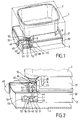
- the device shown in Figures 1 to 6 is a fryer comprising a housing 1 having an upper opening receiving a tank 2 provided for receiving a cooking liquid.
- the upper opening may be closed by a cover, not shown in the figures.
- the housing 1 also has a lateral opening in which is engaged a drain receptacle 3.
- the tank 2 comprises a drain device 10.
- the tank 2 is advantageously removable and comprises means, such as feet 8, provided to allow the tank to be placed on a work plane.
- electric heating means 9 can be fixed under the tank 2.
- the electric heating means can be arranged in the housing 1 or in the tank 2.
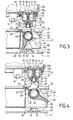
- the emptying device 10 comprises a discharge duct 15 coming from the bottom of the tank 2.
- the duct 15 is protected by a filter 14.
- a spring-loaded damper 20 closes the lower part of the duct 15.
- a thermostatic valve 16 is arranged between the filter 14 and the spring valve 20.
- the duct 15 is formed by a body 11 advantageously made of a plastic material resistant to the high temperatures of the cooking bath, for example Amodel resistant up to 250 ° C in the case of a fryer.
- the body 11 is removably mounted relative to the tank 2.
- a seal 19 is interposed between the tank 2 and the body 11. The seal 19 is advantageously integral with the body 11 to avoid loss during disassembly of the emptying device or an omission during reassembling said device.
- the filter 14 is removably mounted relative to the tank 2 and the body 11. According to the embodiment illustrated in the figures, the filter 14 is secured to a ring 13 assembled by bayonet with the body 11.
- the ring 13 is housed removably in a recess in the bottom of the tank 2.
- the ring 13 is immobilized in rotation relative to the tank 2.
- the upper part of the body 11 is engaged in an opening in the bottom of the tank 2, and carries ramps 11a cooperating with ramps 13a of the crown 13 to form the bayonet connection.
- the thermostatic valve 16 comprises a bimetallic flip cup 17 fixed on the underside of a perforated plate 18 closing the upper end of the body 11.
- the plate 18 is for example crimped inside the body 11.
- the cup 17 is shown in Figures 3 and 4 in the open position corresponding to the low temperature position.
- the cup 17 in the high temperature position closes the duct 15 by bearing against an internal annular shoulder 12 of the body 11.
- the transition temperature between the high temperature position and the low temperature position during cooling is for example of the order of 90 ° C in the case of a fryer.
- the spring valve 20 comprises a movable closure part 21 equipped with an O-ring 22.
- the part 21 is mounted on a spring 23 bearing against the underside of the cup 17.
- the rest position of the spring 23 corresponds to the figure 3 in which the valve 20 is closed.
- the emptying receptacle 3 has a sufficient capacity to receive the cooking bath contained in the tank 2.
- the maximum recommended amount of cooking bath for said apparatus is defined by a marking 4 on an inner face of the tank 2, such as visible at the figure 1 .
- the capacity of the emptying receptacle 3 is greater than this maximum recommended volume.
- the capacity of the emptying receptacle is 2.4 liters while the total capacity of the tank corresponds to a volume of 5.5 liters.
- the emptying receptacle comprises a collecting tank 30 closed by a lid 31.
- the recovery tank 30 comprises an upper rib 36 engaged in a lower groove 37 of the cover 31.
- the emptying receptacle 3 has an outer lateral face 32.
- the face 32 may be made at least partially of transparent or translucent material to allow the user to see the filling of the emptying receptacle 3.
- the face 32 comprises a viewing window 34.
- the lid has a discharge opening closed by a drain plug 35.
- the drain receptacle 3 also comprises a control mechanism 40 of the drain, advantageously mounted on the recovery tank 30.
- the control mechanism 40 comprises a movable control member 42 mounted around an intake duct 41 opening into a wall Lateral 33 of the tray 30.
- the movable control part 42 has a funnel 43 and a cam 44 provided for actuating the spring valve 20.
- the movable control member 42 is connected to an operating knob 45 mounted on the outer side face 32 of the emptying receptacle 3.
- the operating knob 45 drives the part 42 in rotation.
- the side wall of the duct 41 has a filling opening 46 surrounded by an O-ring 47 so as to ensure a seal between the duct 41 and the movable control part 42.
- the operating knob 45 is movable between a so-called use position corresponding to figures 2 and 3 and a so-called emptying position corresponding to figures 1 and 4 . In the emptying position, as best seen in the figure 4 , the funnel 43 is disposed above the filling opening 46, and the cam 44 pushes the valve 20.
- the apparatus comprises a safety device 25 for preventing the withdrawal of the emptying receptacle 3 when the valve 20 is open.
- the lower end of the duct 15 has a longitudinal slot 26 and the cam 44 arranged partly in the funnel 43 is inserted into the slot 26 during the rotation of the movable control member 42 to the position of emptying, as shown in figure 4 .
- the control mechanism 40 thus comprises a bolt 27 designed to cooperate with a striker 28 belonging to the valve 20 when the valve is brought into the open position, the bolt 27 being formed by a lateral face of the cam 44, the striker 28 being formed by the slot 26.
- the apparatus comprises another safety device 50 intended to prevent two consecutive emptyings.
- a movable safety part 51 is arranged between the housing 1 and the emptying receptacle 3.
- the part 51 is guided by guide stops 52.
- the longitudinal movement of the part 51 is limited by stops 53
- a flexible blade 54 mounted on the workpiece 51 is provided to abut against the drain receptacle 3 when placing said receptacle in the housing 1, as shown in FIG. figure 5 , then to bear against the emptying receptacle 3 when the piece 51 is blocked by one of the stops 53.
- the figure 6 shows the emptying receptacle 3 after its introduction in the housing 1.
- the part 51 comprises a first cam 55 provided to cooperate with a tab 48 from the movable control part 42 when the button operating member 45 is brought into the emptying position after the introduction of the emptying receptacle 3.
- the part 51 comprises a second cam 56 designed to cooperate with the tab 48 when the operating knob 45 is returned to the position of use after a drain.
- the part 51 comprises a blocking stopper 57 provided for blocking the rotation of the movable control part 42 when the operating knob 45 is returned to the emptying position after a new use without removal of the emptying receptacle 3.
- the present embodiment operates as follows.
- the cam 44 can not reach the movable shutter member 21 of the valve 20 protected by the lower end of the duct 15.
- the emptying receptacle 3 comes into operation. contact with the flexible blade 54, as shown in FIG. figure 5 and pushing the movable safety member 51 away from the side opening of the housing 1.
- the flexible blade 54 is erased and rubs against the drain receptacle 3.
- the flexible blade 54 makes it possible to hold the piece 51 in place with respect to the emptying receptacle 3.
- the user can turn the operating knob 45 to the emptying position shown in FIGS. figures 1 and 4 .
- the tab 48 pushes the cam 55 and moves the security piece 51 to an intermediate position.
- the cam 44 pushes back the closing piece 21 of the valve 20, as shown in FIG. figure 4 .
- the liquid contained in the tank 2 can flow through the funnel 43 and the filling opening 46 of the duct 41 to the receptacle 3 if the thermostatic valve 16 is open.
- the cam 44 blocked by the slot 26 prevents the withdrawal of the emptying receptacle 3.
- the user returns the operating knob 45 to the position of use, shown in FIG. figure 3 .
- the tab 48 pushes the cam 56 and moves the security piece 51 to an advanced position shown in FIG. figure 2 .
- the cam 44 releases the drain device 10 and the valve 20 closes.
- the tab 48 releases the security part 51. The user can then remove the emptying receptacle 3.
- the safety device 50 prevents a second emptying if the emptying receptacle 3 has not been removed at least partially from the housing 1 and then replaced, thanks to the movements of the part 51 during the operation of the control device 40 from the operating position to the drain and return position, and when removing and replacing the drain receptacle 3.
- the capacity of the emptying receptacle 3 can thus be limited to the contents of the tank 2, without the risk of overflow due to two consecutive emptyings of the tank 2.
- the user can thus filter the cooking bath by draining it into the receptacle 3.
- the user can also keep the cooking bath protected from the air in the receptacle 3, which makes it possible to limit the oxidation.
- the user can then remove the receptacle 3 from the housing 1 to pour the contents of the receptacle 3 into the tank 2, if he wishes to carry out a new cooking, or in a storage tank for reprocessing, if the bath of cooking is too used.
- the device is thus easy and safe to use.
- the device has a compact construction compatible with domestic use.
- the cover can in particular be slidably mounted or pivoted.
- the drain plug 35 may be disposed on a side face or on the underside of the receptacle 3. The presence of the drain plug is however not necessary, the user can use the filling opening 46 , or possibly remove the lid, to drain the contents of the receptacle 3.
- the operating button 45 may be mounted on a side face of the emptying receptacle housed inside the housing when said receptacle is in place in the housing. The operating button can then be accessed by a hatch formed in the side wall of the housing.
- the operating button 45 may be mounted on the housing 1 of the device, for example opposite the side window of the housing for the insertion of the emptying receptacle.
- the connection between the operating knob and the control mechanism is made during the insertion of the emptying receptacle into the housing.
- the flexible blade 54 may be mounted on one of the outer faces of the drain receptacle or on another inner face of the housing.
- the drain receptacle 3 can form a base removably receiving the housing surrounding the tank.
Landscapes
- Engineering & Computer Science (AREA)
- Food Science & Technology (AREA)
- Frying-Pans Or Fryers (AREA)
- Crushing And Pulverization Processes (AREA)
- Filling Of Jars Or Cans And Processes For Cleaning And Sealing Jars (AREA)
- Drying Of Solid Materials (AREA)
Claims (17)
- Kochgerät mit einem Gehäuse (1) und in diesem Gehäuse (1) einer Wanne (2), die dazu vorgesehen ist, ein Garbad aufzunehmen, und mit einer Entleerungsvorrichtung (10) versehen ist, die für ein Ausgießen des Inhalts der Wanne (2) in ein Entleerungsgefäß (3) vorgesehen ist, dessen Fassungsvermögen größer als oder gleich groß wie das Volumen des verwendeten Garbads ist und das eine Einfüllöffnung (46) aufweist, die durch ein bewegliches Teil (42) verschlossen werden kann, der am Entleerungsgefäß (3) angebracht ist.
- Kochgerät nach Anspruch 1, dadurch gekennzeichnet, dass das Entleerungsgefäß (3) ein Fassungsvermögen aufweist, das kleiner als oder gleich 60 % des Fassungsvermögens der Wanne (2) ist.
- Kochgerät nach einem der Ansprüche 1 oder 2, dadurch gekennzeichnet, dass das Entleerungsgefäß (3) ein Fassungsvermögen aufweist, das größer als ein Sechstel des Fassungsvermögens der Wanne (2) ist.
- Kochgerät nach einem der Ansprüche 1 bis 3, dadurch gekennzeichnet, dass das Entleerungsgefäß (3) bezüglich des Gehäuses (1) abnehmbar ist.
- Kochgerät nach Anspruch 4, dadurch gekennzeichnet, dass das Gehäuse (1) eine seitliche Öffnung aufweist, in welche das Entleerungsgefäß (3) mindestens teilweise eingefügt werden kann.
- Kochgerät nach einem der Ansprüche 1 bis 5, dadurch gekennzeichnet, dass das Entleerungsgefäß (3) einen Auffangbehälter (30) aufweist, der mit einem Deckel (31) verschlossen ist.
- Kochgerät nach einem der Ansprüche 1 bis 6, dadurch gekennzeichnet, dass das Entleerungsgefäß (3) eine äußere Seitenfläche (32) aufweist, die mindestens teilweise aus transparentem oder lichtdurchlässigem Material besteht.
- Kochgerät nach Anspruch 7, dadurch gekennzeichnet, dass die äußere Seitenfläche (32) ein Sichtfenster (34) aufweist.
- Kochgerät nach einem der Ansprüche 1 bis 8, dadurch gekennzeichnet, dass das Entleerungsgefäß (3) einen Entleerungsstopfen (35) aufweist.
- Kochgerät nach einem der Ansprüche 1 bis 9, dadurch gekennzeichnet, dass die Einfüllöffnung (46) in einer Einlassleitung (41) ausgebildet ist, die in das Entleerungsgefäß (3) mündet.
- Kochgerät nach Anspruch 10, dadurch gekennzeichnet, dass die Einlassleitung (41) mündet in eine Seitenwand (33) des Entleerungsgefäßes (3).
- Kochgerät nach einem der Ansprüche 1 bis 11, dadurch gekennzeichnet, dass das bewegliche Teil (42) einen Trichter (43) aufweist, der dazu vorgesehen ist, den aus der Entleerungsvorrichtung (10) stammenden Inhalt der Wanne (2) aufzufangen.
- Kochgerät nach einem der Ansprüche 1 bis 12, dadurch gekennzeichnet, dass die Entleerungsvorrichtung (10) eine Abflussleitung (15) aufweist, die durch einen Filter (14) geschützt ist.
- Kochgerät nach einem der Ansprüche 1 bis 13, dadurch gekennzeichnet, dass das bewegliche Teil (42) über einen Bedienknopf (45) betätigt wird, der von außerhalb des Geräts zugänglich ist.
- Kochgerät nach Anspruch 14, dadurch gekennzeichnet, dass der Bedienknopf (45) am Auffanggefäß (3) angebracht ist.
- Kochgerät nach einem der Ansprüche 14 oder 15, dadurch gekennzeichnet, dass der Bedienknopf (45) die Entleerungsvorrichtung (10) steuert.
- Kochgerät nach Anspruch 16, dadurch gekennzeichnet, dass das bewegliche Teil (42) einen Nocken (44) aufweist, der mit einem beweglichen Verschlussteil (21) eines gefederten Ventilelements (20) zusammenwirkt, das zur Entleerungsvorrichtung (10) gehört.
Applications Claiming Priority (2)
| Application Number | Priority Date | Filing Date | Title |
|---|---|---|---|
| FR0113398 | 2001-10-17 | ||
| FR0113398A FR2830737B1 (fr) | 2001-10-17 | 2001-10-17 | Appareil de cuisson a cuve comportant un dispositif de vidange et un receptacle de vidange |
Publications (2)
| Publication Number | Publication Date |
|---|---|
| EP1304062A1 EP1304062A1 (de) | 2003-04-23 |
| EP1304062B1 true EP1304062B1 (de) | 2009-01-14 |
Family
ID=8868404
Family Applications (1)
| Application Number | Title | Priority Date | Filing Date |
|---|---|---|---|
| EP02356198A Expired - Lifetime EP1304062B1 (de) | 2001-10-17 | 2002-10-09 | Kochgerät mit Behälter und einer Entleerungsvorrichtung sowie einem Auffanggefäss |
Country Status (4)
| Country | Link |
|---|---|
| EP (1) | EP1304062B1 (de) |
| AT (1) | ATE420586T1 (de) |
| DE (1) | DE60230846D1 (de) |
| FR (1) | FR2830737B1 (de) |
Families Citing this family (3)
| Publication number | Priority date | Publication date | Assignee | Title |
|---|---|---|---|---|
| FR2858537B1 (fr) * | 2003-08-05 | 2007-02-23 | Seb Sa | Appareil electrique de cuisson comportant un socle de vidange |
| GB0422328D0 (en) * | 2004-10-08 | 2004-11-10 | Clayson Andrew | Mechanical assembly |
| FR3089102B1 (fr) * | 2018-11-30 | 2020-12-11 | Seb Sa | Socle de vidange empilable pour appareil electrique de cuisson |
Family Cites Families (7)
| Publication number | Priority date | Publication date | Assignee | Title |
|---|---|---|---|---|
| GB661921A (en) * | 1949-03-22 | 1951-11-28 | Jack Stanley Lewis Kerr | Improvements in or relating to frying equipment |
| CH294626A (de) | 1953-01-08 | 1953-11-30 | Studer Arnold | Backapparat. |
| US2867164A (en) | 1957-07-19 | 1959-01-06 | J C Pitman & Sons Inc | Deep fat frier |
| US3106887A (en) * | 1962-03-21 | 1963-10-15 | Bryl Stephen | Frying pan |
| US3845702A (en) * | 1970-04-01 | 1974-11-05 | Mies Filter Prod Inc | Apparatus for cooking chicken |
| DE9315764U1 (de) * | 1993-10-15 | 1994-02-10 | Dinsing Udo | Friteuse |
| IT243737Y1 (it) | 1998-01-23 | 2002-03-06 | De Longhi Spa | Apparecchiatura per friggere prodotti alimentari |
-
2001
- 2001-10-17 FR FR0113398A patent/FR2830737B1/fr not_active Expired - Fee Related
-
2002
- 2002-10-09 AT AT02356198T patent/ATE420586T1/de not_active IP Right Cessation
- 2002-10-09 EP EP02356198A patent/EP1304062B1/de not_active Expired - Lifetime
- 2002-10-09 DE DE60230846T patent/DE60230846D1/de not_active Expired - Lifetime
Also Published As
| Publication number | Publication date |
|---|---|
| ATE420586T1 (de) | 2009-01-15 |
| DE60230846D1 (de) | 2009-03-05 |
| EP1304062A1 (de) | 2003-04-23 |
| FR2830737A1 (fr) | 2003-04-18 |
| FR2830737B1 (fr) | 2004-01-30 |
Similar Documents
| Publication | Publication Date | Title |
|---|---|---|
| EP1304063B1 (de) | Kochgerät mit Behälter sowie eine Entleerungsvorrichtung | |
| EP3384814A1 (de) | Elektrogerät zum aufwärmen und/oder kochen von lebensmitteln mit dampf | |
| EP2103240B1 (de) | Elektrisches Kochgerät, das einen Sockel zur Stromeinspeisung und zum Entleeren umfasst | |
| FR2863849A1 (fr) | Appareil domestique de cuisson d'aliments sous pression a dispositif de verrouillage ameliore | |
| EP1075203A1 (de) | Fritiergerät mit filteranlage für den haushalt | |
| EP2436289B1 (de) | Elektrisches Kochgerät mit einem schwenkbaren Deckel, der mit einer Vorrichtung zur Wiedergewinnung der Kondensate ausgestattet ist | |
| FR2754696A1 (fr) | Appareil de cuisson electrique comportant un dispositif de condensation des vapeurs de cuisson | |
| EP1304062B1 (de) | Kochgerät mit Behälter und einer Entleerungsvorrichtung sowie einem Auffanggefäss | |
| EP1922965B1 (de) | Gargerät und Vorrichtung zur Hebung und Senkung eines Fritierkorbes zur Entwässerung von gekochten Speisen | |
| EP1435815B1 (de) | Kochgerät mit einem gefäss, umfassend eine ablassvorrichtung mit einem wärmesicherheitsventil | |
| EP1504705B1 (de) | Elektrisches Kochgerät mit einem Entleerungssockel | |
| FR2830735A1 (fr) | Appareil de cuisson a cuve comportant un dispositif de vidange avec filtre | |
| EP1188403B1 (de) | Kochgerät für Nahrungsmittel mit einer abnehmbaren Vorrichtung zum Kondensieren von Kochdämpfen | |
| EP3886660B1 (de) | Kochanordnung mit einem elektrischen kochgerät und einem ablaufbehälter | |
| EP3659477B1 (de) | Stapelbarer ablaufsockel für elektrokochgerät | |
| EP0145511A1 (de) | Fritiergerät mit Handgriff zum Bedienen des Fritierkorbes | |
| WO2020109236A1 (fr) | Ensemble de cuisson comprenant un appareil electrique de cuisson et un socle de vidange | |
| EP3524107A1 (de) | Küchengerät, das eine über eine hydraulische steuerung gesteuerte abflussöffnung umfasst | |
| FR2867669A1 (fr) | Appareil de cuisson a systeme de vidange optimise |
Legal Events
| Date | Code | Title | Description |
|---|---|---|---|
| PUAI | Public reference made under article 153(3) epc to a published international application that has entered the european phase |
Free format text: ORIGINAL CODE: 0009012 |
|
| AK | Designated contracting states |
Designated state(s): AT BE BG CH CY CZ DE DK EE ES FI FR GB GR IE IT LI LU MC NL PT SE SK TR |
|
| AX | Request for extension of the european patent |
Extension state: AL LT LV MK RO SI |
|
| 17P | Request for examination filed |
Effective date: 20030926 |
|
| AKX | Designation fees paid |
Designated state(s): AT BE BG CH CY CZ DE DK EE ES FI FR GB GR IE IT LI LU MC NL PT SE SK TR |
|
| GRAP | Despatch of communication of intention to grant a patent |
Free format text: ORIGINAL CODE: EPIDOSNIGR1 |
|
| GRAS | Grant fee paid |
Free format text: ORIGINAL CODE: EPIDOSNIGR3 |
|
| GRAA | (expected) grant |
Free format text: ORIGINAL CODE: 0009210 |
|
| AK | Designated contracting states |
Kind code of ref document: B1 Designated state(s): AT BE BG CH CY CZ DE DK EE ES FI FR GB GR IE IT LI LU MC NL PT SE SK TR |
|
| REG | Reference to a national code |
Ref country code: GB Ref legal event code: FG4D Free format text: NOT ENGLISH |
|
| REG | Reference to a national code |
Ref country code: CH Ref legal event code: EP |
|
| REG | Reference to a national code |
Ref country code: IE Ref legal event code: FG4D Free format text: LANGUAGE OF EP DOCUMENT: FRENCH |
|
| REF | Corresponds to: |
Ref document number: 60230846 Country of ref document: DE Date of ref document: 20090305 Kind code of ref document: P |
|
| PG25 | Lapsed in a contracting state [announced via postgrant information from national office to epo] |
Ref country code: FI Free format text: LAPSE BECAUSE OF FAILURE TO SUBMIT A TRANSLATION OF THE DESCRIPTION OR TO PAY THE FEE WITHIN THE PRESCRIBED TIME-LIMIT Effective date: 20090114 Ref country code: ES Free format text: LAPSE BECAUSE OF FAILURE TO SUBMIT A TRANSLATION OF THE DESCRIPTION OR TO PAY THE FEE WITHIN THE PRESCRIBED TIME-LIMIT Effective date: 20090425 |
|
| REG | Reference to a national code |
Ref country code: IE Ref legal event code: FD4D |
|
| PG25 | Lapsed in a contracting state [announced via postgrant information from national office to epo] |
Ref country code: AT Free format text: LAPSE BECAUSE OF FAILURE TO SUBMIT A TRANSLATION OF THE DESCRIPTION OR TO PAY THE FEE WITHIN THE PRESCRIBED TIME-LIMIT Effective date: 20090114 Ref country code: SE Free format text: LAPSE BECAUSE OF FAILURE TO SUBMIT A TRANSLATION OF THE DESCRIPTION OR TO PAY THE FEE WITHIN THE PRESCRIBED TIME-LIMIT Effective date: 20090414 Ref country code: PT Free format text: LAPSE BECAUSE OF FAILURE TO SUBMIT A TRANSLATION OF THE DESCRIPTION OR TO PAY THE FEE WITHIN THE PRESCRIBED TIME-LIMIT Effective date: 20090615 |
|
| PG25 | Lapsed in a contracting state [announced via postgrant information from national office to epo] |
Ref country code: EE Free format text: LAPSE BECAUSE OF FAILURE TO SUBMIT A TRANSLATION OF THE DESCRIPTION OR TO PAY THE FEE WITHIN THE PRESCRIBED TIME-LIMIT Effective date: 20090114 Ref country code: CZ Free format text: LAPSE BECAUSE OF FAILURE TO SUBMIT A TRANSLATION OF THE DESCRIPTION OR TO PAY THE FEE WITHIN THE PRESCRIBED TIME-LIMIT Effective date: 20090114 Ref country code: DK Free format text: LAPSE BECAUSE OF FAILURE TO SUBMIT A TRANSLATION OF THE DESCRIPTION OR TO PAY THE FEE WITHIN THE PRESCRIBED TIME-LIMIT Effective date: 20090114 Ref country code: IE Free format text: LAPSE BECAUSE OF FAILURE TO SUBMIT A TRANSLATION OF THE DESCRIPTION OR TO PAY THE FEE WITHIN THE PRESCRIBED TIME-LIMIT Effective date: 20090114 |
|
| PLBE | No opposition filed within time limit |
Free format text: ORIGINAL CODE: 0009261 |
|
| STAA | Information on the status of an ep patent application or granted ep patent |
Free format text: STATUS: NO OPPOSITION FILED WITHIN TIME LIMIT |
|
| PG25 | Lapsed in a contracting state [announced via postgrant information from national office to epo] |
Ref country code: SK Free format text: LAPSE BECAUSE OF FAILURE TO SUBMIT A TRANSLATION OF THE DESCRIPTION OR TO PAY THE FEE WITHIN THE PRESCRIBED TIME-LIMIT Effective date: 20090114 |
|
| 26N | No opposition filed |
Effective date: 20091015 |
|
| PG25 | Lapsed in a contracting state [announced via postgrant information from national office to epo] |
Ref country code: BG Free format text: LAPSE BECAUSE OF FAILURE TO SUBMIT A TRANSLATION OF THE DESCRIPTION OR TO PAY THE FEE WITHIN THE PRESCRIBED TIME-LIMIT Effective date: 20090414 |
|
| BERE | Be: lapsed |
Owner name: SEB S.A. Effective date: 20091031 |
|
| PG25 | Lapsed in a contracting state [announced via postgrant information from national office to epo] |
Ref country code: MC Free format text: LAPSE BECAUSE OF NON-PAYMENT OF DUE FEES Effective date: 20091031 |
|
| REG | Reference to a national code |
Ref country code: CH Ref legal event code: PL |
|
| PG25 | Lapsed in a contracting state [announced via postgrant information from national office to epo] |
Ref country code: GR Free format text: LAPSE BECAUSE OF FAILURE TO SUBMIT A TRANSLATION OF THE DESCRIPTION OR TO PAY THE FEE WITHIN THE PRESCRIBED TIME-LIMIT Effective date: 20090415 Ref country code: CH Free format text: LAPSE BECAUSE OF NON-PAYMENT OF DUE FEES Effective date: 20091031 Ref country code: BE Free format text: LAPSE BECAUSE OF NON-PAYMENT OF DUE FEES Effective date: 20091031 Ref country code: LI Free format text: LAPSE BECAUSE OF NON-PAYMENT OF DUE FEES Effective date: 20091031 |
|
| PG25 | Lapsed in a contracting state [announced via postgrant information from national office to epo] |
Ref country code: IT Free format text: LAPSE BECAUSE OF FAILURE TO SUBMIT A TRANSLATION OF THE DESCRIPTION OR TO PAY THE FEE WITHIN THE PRESCRIBED TIME-LIMIT Effective date: 20090114 |
|
| PG25 | Lapsed in a contracting state [announced via postgrant information from national office to epo] |
Ref country code: LU Free format text: LAPSE BECAUSE OF NON-PAYMENT OF DUE FEES Effective date: 20091009 |
|
| PG25 | Lapsed in a contracting state [announced via postgrant information from national office to epo] |
Ref country code: TR Free format text: LAPSE BECAUSE OF FAILURE TO SUBMIT A TRANSLATION OF THE DESCRIPTION OR TO PAY THE FEE WITHIN THE PRESCRIBED TIME-LIMIT Effective date: 20090114 |
|
| PG25 | Lapsed in a contracting state [announced via postgrant information from national office to epo] |
Ref country code: CY Free format text: LAPSE BECAUSE OF FAILURE TO SUBMIT A TRANSLATION OF THE DESCRIPTION OR TO PAY THE FEE WITHIN THE PRESCRIBED TIME-LIMIT Effective date: 20090114 |
|
| REG | Reference to a national code |
Ref country code: FR Ref legal event code: PLFP Year of fee payment: 14 |
|
| REG | Reference to a national code |
Ref country code: FR Ref legal event code: PLFP Year of fee payment: 15 |
|
| REG | Reference to a national code |
Ref country code: FR Ref legal event code: CA Effective date: 20170322 |
|
| REG | Reference to a national code |
Ref country code: FR Ref legal event code: PLFP Year of fee payment: 16 |
|
| REG | Reference to a national code |
Ref country code: FR Ref legal event code: PLFP Year of fee payment: 17 |
|
| PGFP | Annual fee paid to national office [announced via postgrant information from national office to epo] |
Ref country code: NL Payment date: 20210916 Year of fee payment: 20 |
|
| PGFP | Annual fee paid to national office [announced via postgrant information from national office to epo] |
Ref country code: DE Payment date: 20211008 Year of fee payment: 20 Ref country code: GB Payment date: 20211020 Year of fee payment: 20 |
|
| PGFP | Annual fee paid to national office [announced via postgrant information from national office to epo] |
Ref country code: FR Payment date: 20211029 Year of fee payment: 20 |
|
| REG | Reference to a national code |
Ref country code: DE Ref legal event code: R071 Ref document number: 60230846 Country of ref document: DE |
|
| REG | Reference to a national code |
Ref country code: NL Ref legal event code: MK Effective date: 20221008 |
|
| REG | Reference to a national code |
Ref country code: GB Ref legal event code: PE20 Expiry date: 20221008 |
|
| PG25 | Lapsed in a contracting state [announced via postgrant information from national office to epo] |
Ref country code: GB Free format text: LAPSE BECAUSE OF EXPIRATION OF PROTECTION Effective date: 20221008 |