EP1304062B1 - Cooking apparatus with receptacle having a drain device and a drain-receiving receptacle - Google Patents
Cooking apparatus with receptacle having a drain device and a drain-receiving receptacle Download PDFInfo
- Publication number
- EP1304062B1 EP1304062B1 EP02356198A EP02356198A EP1304062B1 EP 1304062 B1 EP1304062 B1 EP 1304062B1 EP 02356198 A EP02356198 A EP 02356198A EP 02356198 A EP02356198 A EP 02356198A EP 1304062 B1 EP1304062 B1 EP 1304062B1
- Authority
- EP
- European Patent Office
- Prior art keywords
- receptacle
- drain
- cooking appliance
- appliance according
- emptying
- Prior art date
- Legal status (The legal status is an assumption and is not a legal conclusion. Google has not performed a legal analysis and makes no representation as to the accuracy of the status listed.)
- Expired - Lifetime
Links
Images

Classifications
-
- A—HUMAN NECESSITIES
- A47—FURNITURE; DOMESTIC ARTICLES OR APPLIANCES; COFFEE MILLS; SPICE MILLS; SUCTION CLEANERS IN GENERAL
- A47J—KITCHEN EQUIPMENT; COFFEE MILLS; SPICE MILLS; APPARATUS FOR MAKING BEVERAGES
- A47J37/00—Baking; Roasting; Grilling; Frying
- A47J37/12—Deep fat fryers, e.g. for frying fish or chips
- A47J37/1276—Constructional details
- A47J37/1285—Valves or arrangements to drain used oil or food particles settled at the bottom of the frying vessel
Landscapes
- Engineering & Computer Science (AREA)
- Food Science & Technology (AREA)
- Frying-Pans Or Fryers (AREA)
- Crushing And Pulverization Processes (AREA)
- Filling Of Jars Or Cans And Processes For Cleaning And Sealing Jars (AREA)
- Drying Of Solid Materials (AREA)
Abstract
Description
La présente invention se rapporte au domaine technique général des appareils de cuisson comportant une cuve prévue pour recevoir un bain de cuisson. La présente invention concerne plus particulièrement les appareils du type précité comprenant un dispositif de vidange du bain de cuisson contenu dans la cuve.The present invention relates to the general technical field of cooking appliances comprising a tank adapted to receive a cooking bath. The present invention relates more particularly to appliances of the aforementioned type comprising a device for emptying the cooking bath contained in the tank.
La présente invention concerne essentiellement les appareils pour lesquels le bain de cuisson peut être conservé entre deux utilisations. La présente invention concerne les appareils utilisant un bain de cuisson à base d'huile ou de matière grasse fondue, tels que les friteuses.The present invention essentially relates to appliances for which the cooking bath can be stored between two uses. The present invention relates to apparatus using a cooking bath based on oil or melted fat, such as fryers.
Dans les friteuses domestiques, le bain de cuisson est conservé le plus souvent dans la cuve de l'appareil. L'huile ou la matière grasse fondue du bain de cuisson peut être filtrée entre deux utilisations.In domestic fryers, the cooking bath is kept most often in the tank of the apparatus. The oil or the melted fat of the cooking bath can be filtered between two uses.
Il est connu notamment du document
Il est connu du document
Le document
Un appareil selon le préambule de la revendication 1 est connu du document
On constate qu'aucun des appareils précités ne permet la conservation du bain de cuisson dans des conditions satisfaisantes sans demander à l'utilisateur des manipulations fastidieuses.It is noted that none of the aforementioned devices allows the conservation of the cooking bath in satisfactory conditions without asking the user for tedious manipulations.
L'objet de la présente invention est d'améliorer le stockage du bain de cuisson dans un appareil de cuisson comportant une cuve munie d'un dispositif de vidange.The object of the present invention is to improve the storage of the cooking bath in a cooking appliance comprising a tank provided with a draining device.
Un autre objet de la présente invention est d'améliorer la commodité d'utilisation des appareils de cuisson comportant une cuve munie d'un dispositif de vidange.Another object of the present invention is to improve the convenience of use of cooking appliances having a tank provided with a draining device.
Un objet additionnel de la présente invention est de proposer un appareil du type précité dont la construction reste simple.An additional object of the present invention is to provide an apparatus of the aforementioned type whose construction remains simple.
Un objet additionnel de la présente invention est de proposer un appareil du type précité dont la construction soit compacte.An additional object of the present invention is to provide an apparatus of the aforementioned type whose construction is compact.
Ces objets sont atteints avec un appareil de cuisson comportant un boîtier et dans ce boîtier une cuve prévue pour recevoir un bain de cuisson, munie d'un dispositif de vidange prévu pour un déversement du contenu de la cuve dans un réceptacle de vidange dont la capacité est supérieure ou égale au volume du bain de cuisson utilisé, du fait que le réceptacle de vidange est fermé et comporte une ouverture de remplissage susceptible d'être obturée par une pièce mobile montée sur ledit réceptacle de vidange. Après utilisation, tout le volume du bain de cuisson peut être vidangé dans le réceptacle de vidange. Cette disposition permet de conserver le bain de cuisson à l'abri de l'air dans le réceptacle de vidange. La dégradation du bain de cuisson est ainsi limitée, ce qui permet de prolonger la durée d'utilisation du bain de cuisson et/ou obtenir des aliments de meilleure qualité.These objects are achieved with a cooking appliance comprising a housing and in this housing a tank provided to receive a cooking bath, provided with a draining device provided for a discharge of the contents of the tank into a drain receptacle whose capacity is greater than or equal to the volume of the cooking bath used, because the emptying receptacle is closed and has a filling opening may be closed by a movable part mounted on said emptying receptacle. After use, the entire volume of the cooking bath can be drained into the drain receptacle. This arrangement keeps the cooking bath safe from the air in the emptying receptacle. The degradation of the cooking bath is thus limited, which makes it possible to prolong the duration of use of the cooking bath and / or obtain better quality foods.
Avantageusement le réceptacle de vidange présente une capacité inférieure ou égale à 60% de la capacité de la cuve, et de préférence inférieure à la moitié de la capacité de la cuve. Une telle disposition permet d'obtenir un appareil de dimensions compactes. Cette disposition s'applique notamment aux friteuses domestiques. En effet le bon fonctionnement de ces appareils exige de limiter le volume du bain de cuisson. Dans les appareils comportant un élément chauffant disposé sous la cuve, le bain de cuisson remplit rarement plus de la moitié de la cuve. Le volume du bain de cuisson peut dépasser légèrement cette valeur dans les appareils présentant un élément chauffant plongeant.Advantageously, the emptying receptacle has a capacity less than or equal to 60% of the capacity of the tank, and preferably less than half the capacity of the tank. Such an arrangement provides an apparatus of compact dimensions. This provision applies in particular to domestic fryers. Indeed the proper functioning of these devices requires limiting the volume of the cooking bath. In appliances having a heating element disposed under the tank, the cooking bath rarely fills more than half of the tank. The volume of the cooking bath may slightly exceed this value in appliances with a plunging heating element.
Avantageusement encore, le réceptacle de vidange présente une capacité supérieure à un sixième de la capacité de la cuve, une telle disposition permettant notamment de réaliser des fritures en bain d'huile et de pouvoir vidanger le bain de cuisson dans le réceptacle de vidange.Advantageously, the emptying receptacle has a capacity greater than one sixth of the capacity of the tank, such an arrangement allowing in particular to make fried in oil bath and to drain the cooking bath into the emptying receptacle.
Avantageusement, pour faciliter l'utilisation de l'appareil, le réceptacle de vidange est amovible par rapport au boîtier. Selon un exemple de réalisation, le boîtier comporte une ouverture latérale dans laquelle peut être inséré au moins partiellement le réceptacle de vidange. Selon un autre exemple de réalisation, le réceptacle de vidange forme un socle supportant le boîtier.Advantageously, to facilitate the use of the apparatus, the emptying receptacle is removable relative to the housing. According to an exemplary embodiment, the housing has a lateral opening in which the emptying receptacle can be inserted at least partially. According to another embodiment, the emptying receptacle forms a base supporting the housing.
En alternative, le réceptacle de vidange peut être fixe et comporter un dispositif de vidange, la cuve étant alors avantageusement amovible. Un clapet thermostatique peut alors être avantageusement prévu pour le dispositif de vidange du réceptacle de vidange.Alternatively, the emptying receptacle can be fixed and include a drain device, the tank then being advantageously removable. A thermostatic valve can then be advantageously provided for the emptying device of the emptying receptacle.
Selon un mode de réalisation, le réceptacle de vidange comporte un bac récupérateur fermé par un couvercle. Cette disposition facilite le retrait d'un pain de matière grasse figée, ainsi que le nettoyage du réceptacle de vidange. D'autres réalisations sont envisageables, par exemple un réceptacle de vidange obtenu par soufflage.According to one embodiment, the emptying receptacle comprises a collecting tank closed by a lid. This arrangement facilitates the removal of a frozen fat cake, as well as the cleaning of the emptying receptacle. Other embodiments are possible, for example a discharge receptacle obtained by blowing.
Avantageusement, pour permettre la visualisation du contenu, le réceptacle de vidange comporte une face latérale extérieure réalisée au moins partiellement en matériau transparent ou translucide. La face latérale extérieure peut notamment comporter une fenêtre de visualisation.Advantageously, to allow visualization of the contents, the emptying receptacle comprises an outer lateral face made at least partially of transparent or translucent material. The outer side face may include in particular a viewing window.
Avantageusement, pour faciliter le déversement du contenu, le réceptacle de vidange comporte un bouchon de vidange.Advantageously, to facilitate the discharge of the contents, the emptying receptacle comprises a drain plug.
Avantageusement, pour faciliter l'implantation de la pièce mobile, l'ouverture de remplissage est ménagée dans un conduit d'admission débouchant dans le réceptacle de vidange.Advantageously, to facilitate the implantation of the moving part, the filling opening is formed in an intake duct opening into the emptying receptacle.
Avantageusement alors le conduit d'admission débouche dans une paroi latérale du réceptacle de vidange. Cette disposition permet notamment de réaliser un réceptacle de vidange en deux parties avec une partie souple supérieure prévue pour être retirée d'une partie inférieure plus rigide formant un réservoir, le conduit d'admission débouchant dans le réservoir.Advantageously then the intake duct opens into a side wall of the emptying receptacle. This arrangement allows in particular to achieve a two-part discharge receptacle with an upper flexible portion adapted to be removed from a lower rigid portion forming a reservoir, the intake duct opening into the reservoir.
Avantageusement, pour faciliter la vidange du contenu de la cuve, la pièce mobile présente un entonnoir prévu pour recueillir le contenu de la cuve issu du dispositif de vidange.Advantageously, to facilitate the emptying of the contents of the tank, the moving part has a funnel provided to collect the contents of the tank from the emptying device.
Avantageusement, pour améliorer la qualité du bain de cuisson pour les utilisations suivantes, le dispositif de vidange comporte un conduit d'évacuation protégé par un filtre.Advantageously, to improve the quality of the cooking bath for the following uses, the emptying device comprises a discharge duct protected by a filter.
Avantageusement pour faciliter l'utilisation de l'appareil la pièce mobile est actionnée par un bouton de manoeuvre accessible de l'extérieur de l'appareil.Advantageously to facilitate the use of the device the moving part is actuated by an operating knob accessible from the outside of the device.
Avantageusement alors, le bouton de manoeuvre est monté sur le réceptacle de vidange, cette disposition permettant de simplifier la construction.Advantageously then, the operating knob is mounted on the emptying receptacle, this provision for simplifying the construction.
Avantageusement encore, pour simplifier l'utilisation de l'appareil, le bouton de manoeuvre commande le dispositif de vidange.Advantageously, to simplify the use of the apparatus, the operating knob controls the emptying device.
Selon un mode de réalisation préféré la pièce mobile comporte une came coopérant avec une pièce mobile d'obturation d'un clapet à ressort appartenant au dispositif de vidange.According to a preferred embodiment, the moving part comprises a cam cooperating with a movable piece for closing a spring valve belonging to the emptying device.
L'invention sera mieux comprise à l'étude de l'exemple de réalisation suivant, pris à titre nullement limitatif, illustré dans les figures annexées, dans lesquelles :
- la
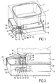
figure 1 est une vue montrant un appareil de cuisson selon l'invention, dans la position prévue pour la vidange du contenu de la cuve, le boîtier extérieur étant représenté en pointillés, - la
figure 2 est une vue partielle de l'appareil montré à lafigure 1 , dans une position après la vidange de la cuve, montrant le dispositif de sécurité prévu pour éviter deux vidanges consécutives sans retrait du réceptacle de vidange, - la
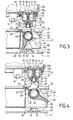
figure 3 est une vue partielle en coupe transversale de l'appareil montré à lafigure 1 , dans une position après la vidange de la cuve, - la
figure 4 est une vue partielle en coupe transversale de l'appareil montré à lafigure 1 , dans la position prévue pour la vidange du contenu de la cuve, - la
figure 5 est une vue partielle du réceptacle de vidange lors de sa remise en place dans le boîtier, - la
figure 6 est une vue partielle du réceptacle de vidange remis en place dans le boîtier, avant une nouvelle opération de vidange.
- the
figure 1 is a view showing a cooking apparatus according to the invention, in the position provided for emptying the contents of the tank, the outer housing being shown in dashed lines, - the
figure 2 is a partial view of the device shown in thefigure 1 in a position after emptying the tank, showing the safety device provided to prevent two consecutive emptyings without removal of the emptying receptacle, - the
figure 3 is a partial cross-sectional view of the apparatus shown atfigure 1 in a position after emptying the tank, - the
figure 4 is a partial cross-sectional view of the apparatus shown atfigure 1 in the position intended for emptying the contents of the tank, - the
figure 5 is a partial view of the emptying receptacle when it is put back into the housing, - the
figure 6 is a partial view of the emptying receptacle replaced in the housing, before a new emptying operation.
L'appareil illustré aux
Tel que mieux visible aux
Le dispositif de vidange 10 comprend un conduit d'évacuation 15 issu du fond de la cuve 2. Le conduit 15 est protégé par un filtre 14. Un clapet à ressort 20 obture la partie inférieure du conduit 15. Un clapet thermostatique 16 est agencé entre le filtre 14 et le clapet à ressort 20.The emptying
Le conduit 15 est formé par un corps 11 avantageusement réalisé en une matière plastique résistante aux températures élevées du bain de cuisson, par exemple de l'Amodel résistant jusqu'à 250°C dans le cas d'une friteuse. Le corps 11 est monté amovible par rapport la cuve 2. Un joint 19 est interposé entre la cuve 2 et le corps 11. Le joint 19 est avantageusement solidaire du corps 11 pour éviter une perte lors du démontage du dispositif de vidange ou un oubli lors du remontage dudit dispositif.The
Le filtre 14 est monté amovible par rapport à la cuve 2 et au corps 11. Selon l'exemple de réalisation illustré aux figures, le filtre 14 est solidaire d'une couronne 13 assemblée par baïonnette avec le corps 11. La couronne 13 est logée de manière amovible dans un renfoncement du fond de la cuve 2. La couronne 13 est immobilisée en rotation par rapport à la cuve 2. La partie supérieure du corps 11 est engagée dans une ouverture ménagée dans le fond de la cuve 2, et porte des rampes 11a coopérant avec des rampes 13a de la couronne 13 pour former l'assemblage par baïonnette.The
Le clapet thermostatique 16 comprend une coupelle bimétallique à retournement 17 fixée sur la face inférieure d'une plaque perforée 18 obturant l'extrémité supérieure du corps 11. La plaque 18 est par exemple sertie à l'intérieur du corps 11.The
La coupelle 17 est représentée aux
Le clapet à ressort 20 comporte une pièce mobile d'obturation 21 équipée d'un joint périphérique torique 22. La pièce 21 est montée sur un ressort 23 s'appuyant contre la face inférieure de la coupelle 17. La position de repos du ressort 23 correspond à la
Le réceptacle de vidange 3 présente une capacité suffisante pour recevoir le bain de cuisson contenu dans la cuve 2. Usuellement le volume maximal de bain de cuisson conseillé pour ledit appareil est défini par un marquage 4 sur une face intérieure de la cuve 2, tel que visible à la
Le réceptacle de vidange comprend un bac récupérateur 30 fermé par un couvercle 31. Tel que visible aux
Le réceptacle de vidange 3 présente une face latérale extérieure 32. Si désiré, la face 32 peut être réalisée au moins partiellement en matériau transparent ou translucide pour permettre à l'utilisateur de voir le remplissage du réceptacle de vidange 3. Tel que montré à la
Le réceptacle de vidange 3 comprend également un mécanisme de commande 40 de la vidange, avantageusement monté sur le bac récupérateur 30. Le mécanisme de commande 40 comprend une pièce mobile de commande 42 montée autour d'un conduit d'admission 41 débouchant dans une paroi latérale 33 du bac 30. La pièce mobile de commande 42 présente un entonnoir 43 et une came 44 prévue pour actionner le clapet à ressort 20. La pièce mobile de commande 42 est reliée à un bouton de manoeuvre 45 monté sur la face latérale extérieure 32 du réceptacle de vidange 3.The
Le bouton de manoeuvre 45 entraîne la pièce 42 en rotation. La paroi latérale du conduit 41 présente une ouverture de remplissage 46 entourée par un joint torique 47 de manière à assurer une étanchéité entre le conduit 41 et la pièce mobile de commande 42. Le bouton de manoeuvre 45 est mobile entre une position dite d'utilisation correspondant aux
L'appareil comporte un dispositif de sécurité 25 destiné à empêcher le retrait du réceptacle de vidange 3 lorsque le clapet 20 est ouvert. A cet effet l'extrémité inférieure du conduit 15 présente une fente longitudinale 26 et la came 44 agencée en partie dans l'entonnoir 43 vient s'insérer dans la fente 26 lors de la rotation de la pièce mobile de commande 42 vers la position de vidange, tel que montré à la
L'appareil comporte un autre dispositif de sécurité 50 destiné à empêcher deux vidanges consécutives.The apparatus comprises another
A cet effet une pièce mobile de sécurité 51 est agencée entre le boîtier 1 et le réceptacle de vidange 3. La pièce 51 est guidée par des butées de guidage 52. Le mouvement longitudinal de la pièce 51 est limité par des butées d'arrêt 53. Une lame flexible 54 montée sur la pièce 51 est prévue pour venir en butée contre le réceptacle de vidange 3 lors de la mise en place dudit réceptacle dans le boîtier 1, tel que montré à la
La
La présente réalisation fonctionne de la manière suivante.The present embodiment operates as follows.
Lorsque l'utilisateur met en place le réceptacle de vidange 3 dans le boîtier 1, la came 44 ne peut atteindre la pièce mobile d'obturation 21 du clapet 20 protégée par l'extrémité inférieure du conduit 15. Le réceptacle de vidange 3 vient en contact avec la lame flexible 54, tel que montré à la
Lorsque le réceptacle de vidange 3 est en place dans le boîtier 1, tel qu'illustré à la
Pour retirer le réceptacle de vidange 3 du boîtier 1, l'utilisateur ramène le bouton de manoeuvre 45 vers la position d'utilisation, montrée à la
Grâce à la pièce de sécurité 51, une nouvelle vidange est interdite si le réceptacle de vidange 3 n'a pas été retiré du boîtier 1 puis remis en place. En effet, lors de la rotation de la pièce de commande 42 la patte 48 est arrêtée par la butée 57 et la came 44 ne peut atteindre le clapet 20. Pour autoriser une nouvelle vidange, il est nécessaire de retirer le réceptacle 3 jusqu'à la libération de la lame flexible 54, tel qu'illustré à la
Le dispositif de sécurité 50 interdit de procéder à une deuxième vidange si le réceptacle de vidange 3 n'a pas été retiré au moins partiellement du boîtier 1 puis remis en place, grâce aux déplacements de la pièce 51 lors de la manoeuvre du dispositif de commande 40 de la position d'utilisation vers la position de vidange et retour, ainsi que lors du retrait puis de la remise en place du réceptacle de vidange 3.The
La capacité du réceptacle de vidange 3 peut ainsi être limitée au contenu de la cuve 2, sans risquer de débordement dû à deux vidanges consécutives de la cuve 2.The capacity of the emptying
L'utilisateur peut ainsi filtrer le bain de cuisson en le vidangeant dans le réceptacle 3. L'utilisateur peut également conserver le bain de cuisson à l'abri de l'air dans le réceptacle 3, ce qui permet de limiter l'oxydation. L'utilisateur peut ensuite retirer le réceptacle 3 du boîtier 1 pour verser le contenu du réceptacle 3 dans la cuve 2, s'il désire réaliser une nouvelle cuisson, ou dans un réservoir de stockage en vue d'un retraitement, si le bain de cuisson est trop usagé.The user can thus filter the cooking bath by draining it into the
L'appareil est ainsi d'une utilisation simple et sûre. De plus l'appareil présente une construction compacte compatible avec un usage domestique.The device is thus easy and safe to use. In addition the device has a compact construction compatible with domestic use.
A titre de variante, d'autres moyens de solidarisation du couvercle 31 sur le bac 30 peuvent être envisagés. Le couvercle peut notamment être monté coulissant ou encore pivotant.Alternatively, other means of securing the
A titre de variante, le bouchon de vidange 35 peut être disposé sur une face latérale voire sur la face inférieure du réceptacle 3. La présence du bouchon de vidange n'est cependant pas nécessaire, l'utilisateur pouvant utiliser l'ouverture de remplissage 46, ou éventuellement retirer le couvercle, pour vidanger le contenu du réceptacle 3.Alternatively, the
A titre de variante, le bouton de manoeuvre 45 peut être monté sur une face latérale du réceptacle de vidange logée à l'intérieur du boîtier lorsque ledit réceptacle est en place dans le boîtier. Le bouton de manoeuvre peut alors être accessible par une trappe ménagée dans la paroi latérale du boîtier.Alternatively, the
A titre de variante, le bouton de manoeuvre 45 peut être monté sur le boîtier 1 de l'appareil, par exemple à l'opposé de la fenêtre latérale du boîtier permettant l'insertion du réceptacle de vidange. La connexion entre le bouton de manoeuvre et le mécanisme de commande se fait lors de l'insertion du réceptacle de vidange dans le boîtier.Alternatively, the
A titre de variante, la lame flexible 54 peut être montée sur une des faces externes du réceptacle de vidange ou encore sur une autre face interne du boîtier.Alternatively, the
A titre de variante, le réceptacle de vidange 3 peut former un socle recevant de manière amovible le boîtier entourant la cuve.Alternatively, the
La présente invention n'est nullement limitée aux exemples de réalisation décrits et à leurs variantes, mais englobe de nombreuses modifications dans le cadre des revendications.The present invention is in no way limited to the described exemplary embodiments and their variants, but encompasses many modifications within the scope of the claims.
Claims (17)
- A cooking appliance comprising a housing (1), and, inside said housing (1), a vessel (2) designed to receive a cooking bath, and provided with a drain device (10) designed to empty the contents of the vessel (2) into a drain receptacle (3) of capacity greater than or equal to volume of the cooking bath used, said cooking appliance being characterized in that the drain receptacle (3) is closed and is provided with a filling opening (46) suitable for being shut off by a moving part (42) mounted on said drain receptacle (3).
- A cooking appliance according to claim 1, characterized in that the drain receptacle (3) presents a capacity less than or equal to 60% of the capacity of the vessel (2).
- A cooking appliance according to claim 1 or claim 2, characterized in that the drain receptacle (3) presents a capacity greater than one sixth of the capacity of the vessel (2).
- A cooking appliance according to any one of claims 1 to 3, characterized in that the drain receptacle (3) is removable relative to the housing (1).
- A cooking appliance according to claim 4, characterized in that the housing (1) is provided with a side opening into which the drain receptacle (3) can be inserted at least in part.
- A cooking appliance according to any one of claims 1 to 5, characterized in that the drain receptacle (3) comprises a collector pan (30) closed by a lid (31).
- A cooking appliance according to any one of claims 1 to 6, characterized in that the drain receptacle (3) has an outer side face (32) that is made, at least in part, of a transparent or translucent material.
- A cooking appliance according to claim 7, characterized in that the outer side face (32) is provided with an inspection window (34).
- A cooking appliance according to any one of claims 1 to 8, characterized in that the drain receptacle (3) is provided with a drain stopper (35).
- A cooking appliance according to any one of claims 1 to 9, characterized in that the filling opening (46) is provided in an inlet duct (41) that opens out into the drain receptacle (3).
- A cooking appliance according to claim 10, characterized in that the inlet duct (41) opens out in a side wall (33) of the drain receptacle (3).
- A cooking appliance according to any one of claims 1 to 11, characterized in that the moving part (42) presents a funnel (43) designed to receive the contents of the vessel (2) coming from the drain device (10).
- A cooking appliance according to any one of claims 1 to 12, characterized in that the drain device (10) comprises a discharge duct (15) protected by a filter (14).
- A cooking appliance according to any one of claims 1 to 13, characterized in that the moving part (42) is actuated by an operating button (45) that is accessible from outside the appliance.
- A cooking appliance according to claim 14, characterized in that the operating button (45) is mounted on the drain receptacle (3).
- A cooking appliance according to claim 14 or 15, characterized in that the operating button (45) controls the drain device (10).
- A cooking appliance according to claim 16, characterized in that the moving part (42) is provided with a cam (44) co-operating with a moving shut-off part (21) of a spring-loaded valve (20) that is part of the drain device (10).
Applications Claiming Priority (2)
| Application Number | Priority Date | Filing Date | Title |
|---|---|---|---|
| FR0113398A FR2830737B1 (en) | 2001-10-17 | 2001-10-17 | TANK COOKING APPARATUS COMPRISING A DRAINING DEVICE AND A DRAINING CONTAINER |
| FR0113398 | 2001-10-17 |
Publications (2)
| Publication Number | Publication Date |
|---|---|
| EP1304062A1 EP1304062A1 (en) | 2003-04-23 |
| EP1304062B1 true EP1304062B1 (en) | 2009-01-14 |
Family
ID=8868404
Family Applications (1)
| Application Number | Title | Priority Date | Filing Date |
|---|---|---|---|
| EP02356198A Expired - Lifetime EP1304062B1 (en) | 2001-10-17 | 2002-10-09 | Cooking apparatus with receptacle having a drain device and a drain-receiving receptacle |
Country Status (4)
| Country | Link |
|---|---|
| EP (1) | EP1304062B1 (en) |
| AT (1) | ATE420586T1 (en) |
| DE (1) | DE60230846D1 (en) |
| FR (1) | FR2830737B1 (en) |
Families Citing this family (3)
| Publication number | Priority date | Publication date | Assignee | Title |
|---|---|---|---|---|
| FR2858537B1 (en) * | 2003-08-05 | 2007-02-23 | Seb Sa | ELECTRIC COOKING APPARATUS COMPRISING A DRAIN STAND |
| GB0422328D0 (en) * | 2004-10-08 | 2004-11-10 | Clayson Andrew | Mechanical assembly |
| FR3089102B1 (en) * | 2018-11-30 | 2020-12-11 | Seb Sa | STACKABLE DRAIN BASE FOR ELECTRIC COOKING APPLIANCE |
Family Cites Families (7)
| Publication number | Priority date | Publication date | Assignee | Title |
|---|---|---|---|---|
| GB661921A (en) * | 1949-03-22 | 1951-11-28 | Jack Stanley Lewis Kerr | Improvements in or relating to frying equipment |
| CH294626A (en) | 1953-01-08 | 1953-11-30 | Studer Arnold | Baking apparatus. |
| US2867164A (en) | 1957-07-19 | 1959-01-06 | J C Pitman & Sons Inc | Deep fat frier |
| US3106887A (en) * | 1962-03-21 | 1963-10-15 | Bryl Stephen | Frying pan |
| US3845702A (en) * | 1970-04-01 | 1974-11-05 | Mies Filter Prod Inc | Apparatus for cooking chicken |
| DE9315764U1 (en) * | 1993-10-15 | 1994-02-10 | Dinsing Udo | Deep fryer |
| IT243737Y1 (en) | 1998-01-23 | 2002-03-06 | De Longhi Spa | EQUIPMENT FOR FRYING FOOD PRODUCTS |
-
2001
- 2001-10-17 FR FR0113398A patent/FR2830737B1/en not_active Expired - Fee Related
-
2002
- 2002-10-09 AT AT02356198T patent/ATE420586T1/en not_active IP Right Cessation
- 2002-10-09 DE DE60230846T patent/DE60230846D1/en not_active Expired - Lifetime
- 2002-10-09 EP EP02356198A patent/EP1304062B1/en not_active Expired - Lifetime
Also Published As
| Publication number | Publication date |
|---|---|
| DE60230846D1 (en) | 2009-03-05 |
| EP1304062A1 (en) | 2003-04-23 |
| FR2830737A1 (en) | 2003-04-18 |
| FR2830737B1 (en) | 2004-01-30 |
| ATE420586T1 (en) | 2009-01-15 |
Similar Documents
| Publication | Publication Date | Title |
|---|---|---|
| EP1304063B1 (en) | Cooking apparatus with receptacle having a drain device | |
| EP3384814A1 (en) | Electrical device for heating and/or cooking food with steam | |
| EP1734851B1 (en) | Electrical water heater | |
| EP2103240B1 (en) | Electrical cooking device comprising an electrical supply and drainage base | |
| FR2863849A1 (en) | Pressure cooker for domestic application, has control part with aperture placed at locking valve so that valve occupies upper position within aperture when jaw is in locking position of lid on bowl, to lock control part in its position | |
| EP1075203A1 (en) | Filtering deep fryer for household use | |
| FR2754696A1 (en) | ELECTRIC COOKING APPARATUS COMPRISING A DEVICE FOR CONDENSING COOKING VAPORS | |
| EP1304062B1 (en) | Cooking apparatus with receptacle having a drain device and a drain-receiving receptacle | |
| EP1435815B1 (en) | Cooking appliance with a vessel comprising a draining device with a thermal safety valve | |
| EP1922965A1 (en) | Cooking appliance and device for raising and lowering a basket for draining the cooked food | |
| EP1504705B1 (en) | Electrical cooking appliance containing a drain base | |
| EP2436289B1 (en) | Electrical cooking appliance comprising a hinged lid provided with a condensate-recovery device | |
| FR2830735A1 (en) | Cooking appliance such as deep fryer has fluid drain unit fitted to outside of inner vessel by ring with filter | |
| EP1188403B1 (en) | Cooking appliance for foodstuffs comprising a removable device for condensing cooking vapours | |
| EP3886660B1 (en) | Cooking assembly comprising an electrical cooking appliance and a draining receptacle | |
| EP3659477B1 (en) | Stackable drainage base for an electric cooking appliance | |
| EP0145511A1 (en) | Fryer with a handle for manipulating the basket | |
| WO2020109236A1 (en) | Cooking assembly comprising an electrical cooking appliance and a draining base | |
| EP3524107A1 (en) | Kitchen appliance comprising a drainage core controlled by a hydraulic control | |
| FR2867669A1 (en) | Food cooking appliance e.g. electric fryer, for cooking e.g. vegetable, has tub, receptacle and coupling unit coupled to each other so that preset variation of relative positioning of two of tub, receptacle and unit activates emptying unit |
Legal Events
| Date | Code | Title | Description |
|---|---|---|---|
| PUAI | Public reference made under article 153(3) epc to a published international application that has entered the european phase |
Free format text: ORIGINAL CODE: 0009012 |
|
| AK | Designated contracting states |
Designated state(s): AT BE BG CH CY CZ DE DK EE ES FI FR GB GR IE IT LI LU MC NL PT SE SK TR |
|
| AX | Request for extension of the european patent |
Extension state: AL LT LV MK RO SI |
|
| 17P | Request for examination filed |
Effective date: 20030926 |
|
| AKX | Designation fees paid |
Designated state(s): AT BE BG CH CY CZ DE DK EE ES FI FR GB GR IE IT LI LU MC NL PT SE SK TR |
|
| GRAP | Despatch of communication of intention to grant a patent |
Free format text: ORIGINAL CODE: EPIDOSNIGR1 |
|
| GRAS | Grant fee paid |
Free format text: ORIGINAL CODE: EPIDOSNIGR3 |
|
| GRAA | (expected) grant |
Free format text: ORIGINAL CODE: 0009210 |
|
| AK | Designated contracting states |
Kind code of ref document: B1 Designated state(s): AT BE BG CH CY CZ DE DK EE ES FI FR GB GR IE IT LI LU MC NL PT SE SK TR |
|
| REG | Reference to a national code |
Ref country code: GB Ref legal event code: FG4D Free format text: NOT ENGLISH |
|
| REG | Reference to a national code |
Ref country code: CH Ref legal event code: EP |
|
| REG | Reference to a national code |
Ref country code: IE Ref legal event code: FG4D Free format text: LANGUAGE OF EP DOCUMENT: FRENCH |
|
| REF | Corresponds to: |
Ref document number: 60230846 Country of ref document: DE Date of ref document: 20090305 Kind code of ref document: P |
|
| PG25 | Lapsed in a contracting state [announced via postgrant information from national office to epo] |
Ref country code: FI Free format text: LAPSE BECAUSE OF FAILURE TO SUBMIT A TRANSLATION OF THE DESCRIPTION OR TO PAY THE FEE WITHIN THE PRESCRIBED TIME-LIMIT Effective date: 20090114 Ref country code: ES Free format text: LAPSE BECAUSE OF FAILURE TO SUBMIT A TRANSLATION OF THE DESCRIPTION OR TO PAY THE FEE WITHIN THE PRESCRIBED TIME-LIMIT Effective date: 20090425 |
|
| REG | Reference to a national code |
Ref country code: IE Ref legal event code: FD4D |
|
| PG25 | Lapsed in a contracting state [announced via postgrant information from national office to epo] |
Ref country code: AT Free format text: LAPSE BECAUSE OF FAILURE TO SUBMIT A TRANSLATION OF THE DESCRIPTION OR TO PAY THE FEE WITHIN THE PRESCRIBED TIME-LIMIT Effective date: 20090114 Ref country code: SE Free format text: LAPSE BECAUSE OF FAILURE TO SUBMIT A TRANSLATION OF THE DESCRIPTION OR TO PAY THE FEE WITHIN THE PRESCRIBED TIME-LIMIT Effective date: 20090414 Ref country code: PT Free format text: LAPSE BECAUSE OF FAILURE TO SUBMIT A TRANSLATION OF THE DESCRIPTION OR TO PAY THE FEE WITHIN THE PRESCRIBED TIME-LIMIT Effective date: 20090615 |
|
| PG25 | Lapsed in a contracting state [announced via postgrant information from national office to epo] |
Ref country code: EE Free format text: LAPSE BECAUSE OF FAILURE TO SUBMIT A TRANSLATION OF THE DESCRIPTION OR TO PAY THE FEE WITHIN THE PRESCRIBED TIME-LIMIT Effective date: 20090114 Ref country code: CZ Free format text: LAPSE BECAUSE OF FAILURE TO SUBMIT A TRANSLATION OF THE DESCRIPTION OR TO PAY THE FEE WITHIN THE PRESCRIBED TIME-LIMIT Effective date: 20090114 Ref country code: DK Free format text: LAPSE BECAUSE OF FAILURE TO SUBMIT A TRANSLATION OF THE DESCRIPTION OR TO PAY THE FEE WITHIN THE PRESCRIBED TIME-LIMIT Effective date: 20090114 Ref country code: IE Free format text: LAPSE BECAUSE OF FAILURE TO SUBMIT A TRANSLATION OF THE DESCRIPTION OR TO PAY THE FEE WITHIN THE PRESCRIBED TIME-LIMIT Effective date: 20090114 |
|
| PLBE | No opposition filed within time limit |
Free format text: ORIGINAL CODE: 0009261 |
|
| STAA | Information on the status of an ep patent application or granted ep patent |
Free format text: STATUS: NO OPPOSITION FILED WITHIN TIME LIMIT |
|
| PG25 | Lapsed in a contracting state [announced via postgrant information from national office to epo] |
Ref country code: SK Free format text: LAPSE BECAUSE OF FAILURE TO SUBMIT A TRANSLATION OF THE DESCRIPTION OR TO PAY THE FEE WITHIN THE PRESCRIBED TIME-LIMIT Effective date: 20090114 |
|
| 26N | No opposition filed |
Effective date: 20091015 |
|
| PG25 | Lapsed in a contracting state [announced via postgrant information from national office to epo] |
Ref country code: BG Free format text: LAPSE BECAUSE OF FAILURE TO SUBMIT A TRANSLATION OF THE DESCRIPTION OR TO PAY THE FEE WITHIN THE PRESCRIBED TIME-LIMIT Effective date: 20090414 |
|
| BERE | Be: lapsed |
Owner name: SEB S.A. Effective date: 20091031 |
|
| PG25 | Lapsed in a contracting state [announced via postgrant information from national office to epo] |
Ref country code: MC Free format text: LAPSE BECAUSE OF NON-PAYMENT OF DUE FEES Effective date: 20091031 |
|
| REG | Reference to a national code |
Ref country code: CH Ref legal event code: PL |
|
| PG25 | Lapsed in a contracting state [announced via postgrant information from national office to epo] |
Ref country code: GR Free format text: LAPSE BECAUSE OF FAILURE TO SUBMIT A TRANSLATION OF THE DESCRIPTION OR TO PAY THE FEE WITHIN THE PRESCRIBED TIME-LIMIT Effective date: 20090415 Ref country code: CH Free format text: LAPSE BECAUSE OF NON-PAYMENT OF DUE FEES Effective date: 20091031 Ref country code: BE Free format text: LAPSE BECAUSE OF NON-PAYMENT OF DUE FEES Effective date: 20091031 Ref country code: LI Free format text: LAPSE BECAUSE OF NON-PAYMENT OF DUE FEES Effective date: 20091031 |
|
| PG25 | Lapsed in a contracting state [announced via postgrant information from national office to epo] |
Ref country code: IT Free format text: LAPSE BECAUSE OF FAILURE TO SUBMIT A TRANSLATION OF THE DESCRIPTION OR TO PAY THE FEE WITHIN THE PRESCRIBED TIME-LIMIT Effective date: 20090114 |
|
| PG25 | Lapsed in a contracting state [announced via postgrant information from national office to epo] |
Ref country code: LU Free format text: LAPSE BECAUSE OF NON-PAYMENT OF DUE FEES Effective date: 20091009 |
|
| PG25 | Lapsed in a contracting state [announced via postgrant information from national office to epo] |
Ref country code: TR Free format text: LAPSE BECAUSE OF FAILURE TO SUBMIT A TRANSLATION OF THE DESCRIPTION OR TO PAY THE FEE WITHIN THE PRESCRIBED TIME-LIMIT Effective date: 20090114 |
|
| PG25 | Lapsed in a contracting state [announced via postgrant information from national office to epo] |
Ref country code: CY Free format text: LAPSE BECAUSE OF FAILURE TO SUBMIT A TRANSLATION OF THE DESCRIPTION OR TO PAY THE FEE WITHIN THE PRESCRIBED TIME-LIMIT Effective date: 20090114 |
|
| REG | Reference to a national code |
Ref country code: FR Ref legal event code: PLFP Year of fee payment: 14 |
|
| REG | Reference to a national code |
Ref country code: FR Ref legal event code: PLFP Year of fee payment: 15 |
|
| REG | Reference to a national code |
Ref country code: FR Ref legal event code: CA Effective date: 20170322 |
|
| REG | Reference to a national code |
Ref country code: FR Ref legal event code: PLFP Year of fee payment: 16 |
|
| REG | Reference to a national code |
Ref country code: FR Ref legal event code: PLFP Year of fee payment: 17 |
|
| PGFP | Annual fee paid to national office [announced via postgrant information from national office to epo] |
Ref country code: NL Payment date: 20210916 Year of fee payment: 20 |
|
| PGFP | Annual fee paid to national office [announced via postgrant information from national office to epo] |
Ref country code: DE Payment date: 20211008 Year of fee payment: 20 Ref country code: GB Payment date: 20211020 Year of fee payment: 20 |
|
| PGFP | Annual fee paid to national office [announced via postgrant information from national office to epo] |
Ref country code: FR Payment date: 20211029 Year of fee payment: 20 |
|
| REG | Reference to a national code |
Ref country code: DE Ref legal event code: R071 Ref document number: 60230846 Country of ref document: DE |
|
| REG | Reference to a national code |
Ref country code: NL Ref legal event code: MK Effective date: 20221008 |
|
| REG | Reference to a national code |
Ref country code: GB Ref legal event code: PE20 Expiry date: 20221008 |
|
| PG25 | Lapsed in a contracting state [announced via postgrant information from national office to epo] |
Ref country code: GB Free format text: LAPSE BECAUSE OF EXPIRATION OF PROTECTION Effective date: 20221008 |