EP1302738A2 - Elektrolichtbogenofen mit einem Abgaskrümmer - Google Patents
Elektrolichtbogenofen mit einem Abgaskrümmer Download PDFInfo
- Publication number
- EP1302738A2 EP1302738A2 EP02020613A EP02020613A EP1302738A2 EP 1302738 A2 EP1302738 A2 EP 1302738A2 EP 02020613 A EP02020613 A EP 02020613A EP 02020613 A EP02020613 A EP 02020613A EP 1302738 A2 EP1302738 A2 EP 1302738A2
- Authority
- EP
- European Patent Office
- Prior art keywords
- electric arc
- arc furnace
- furnace
- electrodes
- vessel
- Prior art date
- Legal status (The legal status is an assumption and is not a legal conclusion. Google has not performed a legal analysis and makes no representation as to the accuracy of the status listed.)
- Withdrawn
Links
Images



Classifications
-
- F—MECHANICAL ENGINEERING; LIGHTING; HEATING; WEAPONS; BLASTING
- F27—FURNACES; KILNS; OVENS; RETORTS
- F27B—FURNACES, KILNS, OVENS OR RETORTS IN GENERAL; OPEN SINTERING OR LIKE APPARATUS
- F27B3/00—Hearth-type furnaces, e.g. of reverberatory type; Electric arc furnaces ; Tank furnaces
- F27B3/10—Details, accessories or equipment, e.g. dust-collectors, specially adapted for hearth-type furnaces
- F27B3/12—Working chambers or casings; Supports therefor
- F27B3/16—Walls; Roofs
-
- F—MECHANICAL ENGINEERING; LIGHTING; HEATING; WEAPONS; BLASTING
- F27—FURNACES; KILNS; OVENS; RETORTS
- F27D—DETAILS OR ACCESSORIES OF FURNACES, KILNS, OVENS OR RETORTS, IN SO FAR AS THEY ARE OF KINDS OCCURRING IN MORE THAN ONE KIND OF FURNACE
- F27D17/00—Arrangements for using waste heat; Arrangements for using, or disposing of, waste gases
- F27D17/30—Arrangements for extraction or collection of waste gases; Hoods therefor
- F27D17/304—Arrangements for extraction or collection of waste gases; Hoods therefor specially adapted for electric arc furnaces
-
- F—MECHANICAL ENGINEERING; LIGHTING; HEATING; WEAPONS; BLASTING
- F27—FURNACES; KILNS; OVENS; RETORTS
- F27B—FURNACES, KILNS, OVENS OR RETORTS IN GENERAL; OPEN SINTERING OR LIKE APPARATUS
- F27B3/00—Hearth-type furnaces, e.g. of reverberatory type; Electric arc furnaces ; Tank furnaces
- F27B3/08—Hearth-type furnaces, e.g. of reverberatory type; Electric arc furnaces ; Tank furnaces heated electrically, with or without any other source of heat
- F27B3/085—Arc furnaces
-
- F—MECHANICAL ENGINEERING; LIGHTING; HEATING; WEAPONS; BLASTING
- F27—FURNACES; KILNS; OVENS; RETORTS
- F27D—DETAILS OR ACCESSORIES OF FURNACES, KILNS, OVENS OR RETORTS, IN SO FAR AS THEY ARE OF KINDS OCCURRING IN MORE THAN ONE KIND OF FURNACE
- F27D1/00—Casings; Linings; Walls; Roofs
- F27D1/18—Door frames; Doors, lids or removable covers
- F27D1/1808—Removable covers
- F27D1/1816—Removable covers specially adapted for arc furnaces
-
- F—MECHANICAL ENGINEERING; LIGHTING; HEATING; WEAPONS; BLASTING
- F27—FURNACES; KILNS; OVENS; RETORTS
- F27D—DETAILS OR ACCESSORIES OF FURNACES, KILNS, OVENS OR RETORTS, IN SO FAR AS THEY ARE OF KINDS OCCURRING IN MORE THAN ONE KIND OF FURNACE
- F27D99/00—Subject matter not provided for in other groups of this subclass
- F27D99/0001—Heating elements or systems
- F27D99/0033—Heating elements or systems using burners
- F27D2099/0046—Heating elements or systems using burners with incomplete combustion, e.g. reducing atmosphere
- F27D2099/0048—Post- combustion
Definitions
- the invention relates to an electric arc furnace with a lower vessel and Upper vessel, which is closed in operation by means of an oven lid, also with an exhaust manifold that has an air supply for post-combustion the furnace gases with adjustable spacing or a sliding sleeve with a Combustion chamber or a stationary exhaust pipe is connected.
- the smoke evacuation from the furnace vessel takes place via a water-cooled Exhaust manifold.
- the exhaust manifold is located on the furnace cover above the fourth hole in a bricked-in furnace lid and opens in front of the hinged piece or the sliding sleeve of the stationary exhaust pipe.
- the mouth with a flange is capable of extracting flue gas by ⁇ 5 ° Mistake.
- the distance between the flange and the folding piece is used False air supply for temperature reduction and as air supply for afterburning the furnace gases.
- the invention is based, the amount of false air in the electrode area more controlled and thus a more even heat distribution in the To achieve oven.
- the object is achieved according to the invention in that the exhaust manifold on the side of the furnace as an exhaust hood that widens towards the intake opening formed and covering the lid hole around the electrode or electrodes is arranged.
- the amount of false air can be controlled thermal symmetry of the furnace can be achieved.
- One embodiment provides that the furnace lid with or without significantly reduced Brick lining is carried out, which means a considerable saving in operating costs and associated with downtime.
- Electrodes serve to adapt to the electrodes and provide that in the exhaust hood each has a recess for the retractable or extendable on support arms Electrodes is provided. This will make it necessary to retract or extend Space gained for the support arms.
- the room is wider advantageous that the exhaust hood on its end faces channel-shaped openings for the False air supply forms. This characteristic therefore helps to control the quantity of false air according to the prevailing suction pressure conditions.
- this volume distribution is favorably designed such that the channel-shaped Openings for the supply of false air are arranged symmetrically to the electrodes are.
- the electric arc furnace (Fig. 1) is equipped with a furnace vessel 1, which in one Lower vessel 2 and an upper vessel 3 is divided with an oven lid 4.
- an exhaust manifold 5 is connected to the furnace exhaust over a Folding piece 6 (or a sliding sleeve) into a combustion chamber 7 for afterburning respectively. Afterburning saves energy and can Energy consuming systems are supplied.
- the furnace vessel 1 can Carry out a slight tilting movement, whereby the folding piece 6 (or the sliding sleeve) employed on a flange of the exhaust manifold 5 with a variable gap distance 13 can be.
- An actuator 6a is provided for driving the folding piece 6.
- the furnace vessel 1 is tipped over a tilt cylinder.
- the exhaust manifold 5 is now on the side of the furnace vessel 1 as facing the suction direction 5b extending exhaust hood 5a formed (Fig. 2) and covered the cover hole 4a.
- the furnace cover 4 can be without or only with one reduced brickwork.
- the exhaust hood 5a forms on its end faces 5c channel-shaped openings 11 for the supply of false air.
- the arrows in FIG. 1 and FIG. 2 show the exhaust and false air entry into the exhaust hood 5a for an im AC operation led AC oven.
- the channel-shaped openings 11 for the supply of false air are symmetrical to the Electrodes 10 arranged (Fig. 2).
- a feed pipe 14 can both as drawn through the exhaust hood 5a or directly through the furnace cover 4 his.
- Fig. 3 the suction hood 5a in the upper vessel 3, which connects to the furnace lid 4 and forms the lid hole 4a, visible.
- the three AC electrodes 10 are held by means of the support arm 9.
- the suction hood 5a is approximately U-shaped and the Support arm 9 with the electrode 10 is on or between the U-legs 12a and 12b extendable.
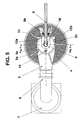
- the end of the U-legs 12a and 12b there is an end face Opening 11 (Fig. 5) arranged for the entry of false air.
- the arrows in FIGS. 4 and 5 also show the exhaust gas and false air entry into the exhaust hood 5a for the DC furnace (Figs. 4 and 5).
Landscapes
- Engineering & Computer Science (AREA)
- Mechanical Engineering (AREA)
- General Engineering & Computer Science (AREA)
- Environmental & Geological Engineering (AREA)
- Vertical, Hearth, Or Arc Furnaces (AREA)
Abstract
Description
- Fig. 1
- einen senkrechten Schnitt durch ein Ofengefäß mit Wechselstrombetrieb und einer angeschlossenen Brennkammer,
- Fig. 2
- die zu Fig. 1 gehörende Draufsicht auf die Ofenanlage für den Wechselstrom-Lichtbogenofen,
- Fig. 3
- einen senkrechten Schnitt durch den oberen Bereich des WechselstromLichtbogenofens,
- Fig. 4
- einen senkrechten Schnitt durch ein Ofengefäß im Gleichstrombetrieb mit einer angeschlossenen Brennkammer,
- Fig. 5
- die zu Fig. 4 gehörende Draufsicht auf die Ofenanlage für den Gleichstrom-Lichtbogenofen und
- Fig. 6
- einen senkrechten Schnitt durch den oberen Bereich des Gleichstrom-Lichtbogenofens.
- 1
- Ofengefäß des Elektrolichtbogenofens
- 2
- Untergefäß
- 3
- Obergefäß
- 4
- Ofendeckel
- 4a
- Deckelloch
- 5
- Abgaskrümmer
- 5a
- Absaughaube
- 5b
- Ansaugrichtung
- 5c
- Stirnseite
- 6
- Klappstück (oder Schiebemuffe)
- 6a
- Stellantrieb
- 7
- Brennkammer
- 8
- Ausnehmung für die Elektrode
- 9
- Tragarm
- 10
- Elektrode
- 11
- Öffnung für Falschluftzutritt
- 12a
- U-Schenkel
- 12b
- U-Schenkel
- 13
- Spaltabstand
- 14
- Beschickungsrohr
Claims (7)
- Elektrolichtbogenofen mit einem Untergefäß und einem Obergefäß, das im Betrieb mittels eines Ofendeckels abgeschlossen ist, ferner mit einem Abgaskrümmer, der über ein für die Luftzuführung zwecks Nachverbrennung der Ofengase im Abstand einstellbares Klappstück oder eine Schiebemuffe mit einer Brennkammer oder einer stationären Abgasleitung in Verbindung steht,
dadurch gekennzeichnet, dass der Abgaskrümmer (5) auf der Seite des Ofengefäßes (1) als sich zur Ansaugöffnung (5b) hin verbreiternde Abgashaube (5a) ausgebildet und das Deckelloch (4a) um die Elektrode (10) oder die Elektroden (10) abdeckend angeordnet ist. - Elektrolichtbogenofen nach Anspruch 1,
dadurch gekennzeichnet, dass der Ofendeckel (4) ohne oder mit erheblich reduzierter Ausmauerung ausgeführt ist. - Elektrolichtbogenofen nach einem der Ansprüche 1 oder 2,
dadurch gekennzeichnet, dass in der Abgashaube (5a) jeweils eine Ausnehmung (8) für die an Tragarmen (9) ein- oder ausfahrbaren Elektroden (10) vorgesehen ist. - Elektrolichtbogenofen nach einem der Ansprüche 1 bis 3,
dadurch gekennzeichnet, dass die Abgashaube (5a) an ihren Stirnseiten (5c) kanalförmige Öffnungen (11) für die Falschluftzufuhr bildet. - Elektrolichtbogenofen nach einem der Ansprüche 1 bis 4,
dadurch gekennzeichnet, dass die kanalförmigen Öffnungen (11) für die Falschluftzufuhr symmetrisch zu den Elektroden (10) angeordnet sind. - Elektrolichtbogenofen nach Anspruch 1,
dadurch gekennzeichnet, dass für einen Gleichstrom-Elektrolichtbogenofen symmetrisch zur mittig angeordneten Elektrode (10) die Absaughaube (5a) etwa U-förmig ausgebildet und dass der Tragarm (9) mit der Elektrode (10) zwischen den U-Schenkeln (12a, 12b) ein- oder ausfahrbar ist. - Elektrolichtbogenofen nach Anspruch 6,
dadurch gekennzeichnet, dass am Ende der U-Schenkel (12a, 12b) jeweils eine stirnseitige Öffnung (11) für den Falschlufteintritt angeordnet ist.
Applications Claiming Priority (2)
| Application Number | Priority Date | Filing Date | Title |
|---|---|---|---|
| DE10150628A DE10150628B4 (de) | 2001-10-12 | 2001-10-12 | Elektrolichtbogenofenanlage mit einem Abgaskrümmer |
| DE10150628 | 2001-10-12 |
Publications (2)
| Publication Number | Publication Date |
|---|---|
| EP1302738A2 true EP1302738A2 (de) | 2003-04-16 |
| EP1302738A3 EP1302738A3 (de) | 2003-10-15 |
Family
ID=7702426
Family Applications (1)
| Application Number | Title | Priority Date | Filing Date |
|---|---|---|---|
| EP02020613A Withdrawn EP1302738A3 (de) | 2001-10-12 | 2002-09-13 | Elektrolichtbogenofen mit einem Abgaskrümmer |
Country Status (2)
| Country | Link |
|---|---|
| EP (1) | EP1302738A3 (de) |
| DE (1) | DE10150628B4 (de) |
Cited By (1)
| Publication number | Priority date | Publication date | Assignee | Title |
|---|---|---|---|---|
| RU169594U1 (ru) * | 2016-02-26 | 2017-03-23 | Открытое акционерное общество "Первоуральский динасовый завод" (ОАО "ДИНУР") | Универсальная электродуговая печь для плавки оксидных материалов |
Family Cites Families (7)
| Publication number | Priority date | Publication date | Assignee | Title |
|---|---|---|---|---|
| AT267566B (de) * | 1964-09-02 | 1969-01-10 | Voest Ag | Abgasführung bei Elektroöfen, insbesondere Lichtbogenöfen |
| DE2203161C2 (de) * | 1972-01-24 | 1973-09-20 | Ceag Dominit Ag, 4600 Dortmund | Absaugvorrichtung fur Elektroofen |
| JPS5878499U (ja) * | 1981-11-21 | 1983-05-27 | 株式会社ニツコ− | 電気炉の廃ガス設備 |
| DE4332913A1 (de) * | 1993-09-23 | 1995-03-30 | Mannesmann Ag | Stahlwerkseinrichtung mit geschlossenem kippbarem Lichtbogenofen |
| IT1288892B1 (it) * | 1996-04-30 | 1998-09-25 | Danieli Off Mecc | Dispositivo di aspirazione dei fumi per forno elettrico ad arco |
| SE510743C2 (sv) * | 1998-02-20 | 1999-06-21 | Almqvist & Wallenbeck Ab | Solidfermenteringsmetod |
| IT1310527B1 (it) * | 1999-01-20 | 2002-02-18 | Danieli Off Mecc | Sistema di tamponamento della regione del delta della voltadi un forno elettrico ad arco |
-
2001
- 2001-10-12 DE DE10150628A patent/DE10150628B4/de not_active Expired - Fee Related
-
2002
- 2002-09-13 EP EP02020613A patent/EP1302738A3/de not_active Withdrawn
Cited By (1)
| Publication number | Priority date | Publication date | Assignee | Title |
|---|---|---|---|---|
| RU169594U1 (ru) * | 2016-02-26 | 2017-03-23 | Открытое акционерное общество "Первоуральский динасовый завод" (ОАО "ДИНУР") | Универсальная электродуговая печь для плавки оксидных материалов |
Also Published As
| Publication number | Publication date |
|---|---|
| DE10150628B4 (de) | 2007-04-19 |
| EP1302738A3 (de) | 2003-10-15 |
| DE10150628A1 (de) | 2003-04-30 |
Similar Documents
| Publication | Publication Date | Title |
|---|---|---|
| EP2166287A2 (de) | Festbrennstoff-Feuerstätte für Gebäude sowie für eine derartige Festbrennstoff-Feuerstätte | |
| DE2740537C3 (de) | Brenner für einen Regenerativ-Winderhitzer | |
| DE10150628B4 (de) | Elektrolichtbogenofenanlage mit einem Abgaskrümmer | |
| DE4209765C2 (de) | Verfahren und Vorrichtung zur Behandlung der Abgase eines Lichtbogenofens | |
| EP0267197B1 (de) | Schmelz- und warmhalteofen | |
| EP0666327A1 (de) | Abgasführung für einen Filter-Staub-Schmelzofen | |
| DE3626889C2 (de) | ||
| EP0446237B1 (de) | Ofenanlage zum einschmelzen von schrott | |
| DE60000773T2 (de) | System zum verschliessen der delta-zone eines elektro-lichtbogenofendeckels | |
| CN217041969U (zh) | 艾奇逊石墨化炉尾气吸收装置 | |
| EP1496325B1 (de) | Verfahren zum kombinierten Entbinden und Sintern von glaskeramischen, keramischen und metallischen Formteilen | |
| DE1608228A1 (de) | Elektro-Reduktionsofen | |
| WO2023052137A1 (de) | Rauchgasreinigungsvorrichtung | |
| DE1069839B (de) | ||
| DE3318796A1 (de) | Nachverbrennvorrichtung, insbesondere zum anschluss an laboroefen | |
| DE816160C (de) | Anordnung zur Gasaufsammlung bei elektrischen OEfen | |
| DE109234C (de) | ||
| DE1189236B (de) | Vorrichtung zur Rauch-, Gas- oder Dampfabsaugung fuer Tiegeloefen | |
| DE324907C (de) | Kanalofen | |
| DE20011419U1 (de) | Kaminfeuerstelle | |
| DE7702674U1 (de) | Wandelement fuer eine vorrichtung zum aufsammeln von abstichgasen bei elektrischen schmelzoefen | |
| EP3574121A1 (de) | Brenner-lanzeneinsatz für einen lichtbogenofen | |
| DE3940165C1 (de) | ||
| DE2458395C3 (de) | Herdflammofen mit rechteckiger Herdoberfläche | |
| DE1205232B (de) | Vorrichtung zur Rauchgasabfuehrung an Elektrooefen |
Legal Events
| Date | Code | Title | Description |
|---|---|---|---|
| PUAI | Public reference made under article 153(3) epc to a published international application that has entered the european phase |
Free format text: ORIGINAL CODE: 0009012 |
|
| 17P | Request for examination filed |
Effective date: 20020913 |
|
| AK | Designated contracting states |
Designated state(s): AT BE BG CH CY CZ DE DK EE ES FI FR GB GR IE IT LI LU MC NL PT SE SK TR |
|
| AX | Request for extension of the european patent |
Extension state: AL LT LV MK RO SI |
|
| PUAL | Search report despatched |
Free format text: ORIGINAL CODE: 0009013 |
|
| RIC1 | Information provided on ipc code assigned before grant |
Ipc: 7F 27D 1/18 B Ipc: 7C 21C 5/52 B Ipc: 7F 27D 17/00 B Ipc: 7F 27B 3/18 A |
|
| AK | Designated contracting states |
Kind code of ref document: A3 Designated state(s): AT BE BG CH CY CZ DE DK EE ES FI FR GB GR IE IT LI LU MC NL PT SE SK TR |
|
| AX | Request for extension of the european patent |
Extension state: AL LT LV MK RO SI |
|
| AKX | Designation fees paid |
Designated state(s): AT BE BG CH CY CZ DE DK EE ES FI FR GB GR IE IT LI LU MC NL PT SE SK TR |
|
| 17Q | First examination report despatched |
Effective date: 20040812 |
|
| GRAP | Despatch of communication of intention to grant a patent |
Free format text: ORIGINAL CODE: EPIDOSNIGR1 |
|
| STAA | Information on the status of an ep patent application or granted ep patent |
Free format text: STATUS: THE APPLICATION HAS BEEN WITHDRAWN |
|
| 18W | Application withdrawn |
Effective date: 20050711 |