EP1300555A2 - Katalysator - Google Patents
Katalysator Download PDFInfo
- Publication number
- EP1300555A2 EP1300555A2 EP02400034A EP02400034A EP1300555A2 EP 1300555 A2 EP1300555 A2 EP 1300555A2 EP 02400034 A EP02400034 A EP 02400034A EP 02400034 A EP02400034 A EP 02400034A EP 1300555 A2 EP1300555 A2 EP 1300555A2
- Authority
- EP
- European Patent Office
- Prior art keywords
- channels
- catalyst according
- sheets
- sections
- coated
- Prior art date
- Legal status (The legal status is an assumption and is not a legal conclusion. Google has not performed a legal analysis and makes no representation as to the accuracy of the status listed.)
- Granted
Links
Images





Classifications
-
- B—PERFORMING OPERATIONS; TRANSPORTING
- B01—PHYSICAL OR CHEMICAL PROCESSES OR APPARATUS IN GENERAL
- B01D—SEPARATION
- B01D53/00—Separation of gases or vapours; Recovering vapours of volatile solvents from gases; Chemical or biological purification of waste gases, e.g. engine exhaust gases, smoke, fumes, flue gases, aerosols
- B01D53/34—Chemical or biological purification of waste gases
- B01D53/92—Chemical or biological purification of waste gases of engine exhaust gases
- B01D53/94—Chemical or biological purification of waste gases of engine exhaust gases by catalytic processes
- B01D53/9445—Simultaneously removing carbon monoxide, hydrocarbons or nitrogen oxides making use of three-way catalysts [TWC] or four-way-catalysts [FWC]
- B01D53/9454—Simultaneously removing carbon monoxide, hydrocarbons or nitrogen oxides making use of three-way catalysts [TWC] or four-way-catalysts [FWC] characterised by a specific device
-
- F—MECHANICAL ENGINEERING; LIGHTING; HEATING; WEAPONS; BLASTING
- F01—MACHINES OR ENGINES IN GENERAL; ENGINE PLANTS IN GENERAL; STEAM ENGINES
- F01N—GAS-FLOW SILENCERS OR EXHAUST APPARATUS FOR MACHINES OR ENGINES IN GENERAL; GAS-FLOW SILENCERS OR EXHAUST APPARATUS FOR INTERNAL-COMBUSTION ENGINES
- F01N3/00—Exhaust or silencing apparatus having means for purifying, rendering innocuous, or otherwise treating exhaust
- F01N3/08—Exhaust or silencing apparatus having means for purifying, rendering innocuous, or otherwise treating exhaust for rendering innocuous
- F01N3/10—Exhaust or silencing apparatus having means for purifying, rendering innocuous, or otherwise treating exhaust for rendering innocuous by thermal or catalytic conversion of noxious components of exhaust
- F01N3/24—Exhaust or silencing apparatus having means for purifying, rendering innocuous, or otherwise treating exhaust for rendering innocuous by thermal or catalytic conversion of noxious components of exhaust characterised by constructional aspects of converting apparatus
- F01N3/28—Construction of catalytic reactors
- F01N3/2803—Construction of catalytic reactors characterised by structure, by material or by manufacturing of catalyst support
- F01N3/2807—Metal other than sintered metal
- F01N3/281—Metallic honeycomb monoliths made of stacked or rolled sheets, foils or plates
-
- F—MECHANICAL ENGINEERING; LIGHTING; HEATING; WEAPONS; BLASTING
- F01—MACHINES OR ENGINES IN GENERAL; ENGINE PLANTS IN GENERAL; STEAM ENGINES
- F01N—GAS-FLOW SILENCERS OR EXHAUST APPARATUS FOR MACHINES OR ENGINES IN GENERAL; GAS-FLOW SILENCERS OR EXHAUST APPARATUS FOR INTERNAL-COMBUSTION ENGINES
- F01N3/00—Exhaust or silencing apparatus having means for purifying, rendering innocuous, or otherwise treating exhaust
- F01N3/08—Exhaust or silencing apparatus having means for purifying, rendering innocuous, or otherwise treating exhaust for rendering innocuous
- F01N3/10—Exhaust or silencing apparatus having means for purifying, rendering innocuous, or otherwise treating exhaust for rendering innocuous by thermal or catalytic conversion of noxious components of exhaust
- F01N3/24—Exhaust or silencing apparatus having means for purifying, rendering innocuous, or otherwise treating exhaust for rendering innocuous by thermal or catalytic conversion of noxious components of exhaust characterised by constructional aspects of converting apparatus
- F01N3/28—Construction of catalytic reactors
- F01N3/2803—Construction of catalytic reactors characterised by structure, by material or by manufacturing of catalyst support
- F01N3/2807—Metal other than sintered metal
- F01N3/281—Metallic honeycomb monoliths made of stacked or rolled sheets, foils or plates
- F01N3/2814—Metallic honeycomb monoliths made of stacked or rolled sheets, foils or plates all sheets, plates or foils being corrugated
-
- F—MECHANICAL ENGINEERING; LIGHTING; HEATING; WEAPONS; BLASTING
- F23—COMBUSTION APPARATUS; COMBUSTION PROCESSES
- F23R—GENERATING COMBUSTION PRODUCTS OF HIGH PRESSURE OR HIGH VELOCITY, e.g. GAS-TURBINE COMBUSTION CHAMBERS
- F23R3/00—Continuous combustion chambers using liquid or gaseous fuel
- F23R3/40—Continuous combustion chambers using liquid or gaseous fuel characterised by the use of catalytic means
-
- B—PERFORMING OPERATIONS; TRANSPORTING
- B01—PHYSICAL OR CHEMICAL PROCESSES OR APPARATUS IN GENERAL
- B01J—CHEMICAL OR PHYSICAL PROCESSES, e.g. CATALYSIS OR COLLOID CHEMISTRY; THEIR RELEVANT APPARATUS
- B01J35/00—Catalysts, in general, characterised by their form or physical properties
- B01J35/50—Catalysts, in general, characterised by their form or physical properties characterised by their shape or configuration
- B01J35/56—Foraminous structures having flow-through passages or channels, e.g. grids or three-dimensional [3D] monoliths
-
- F—MECHANICAL ENGINEERING; LIGHTING; HEATING; WEAPONS; BLASTING
- F01—MACHINES OR ENGINES IN GENERAL; ENGINE PLANTS IN GENERAL; STEAM ENGINES
- F01N—GAS-FLOW SILENCERS OR EXHAUST APPARATUS FOR MACHINES OR ENGINES IN GENERAL; GAS-FLOW SILENCERS OR EXHAUST APPARATUS FOR INTERNAL-COMBUSTION ENGINES
- F01N2330/00—Structure of catalyst support or particle filter
- F01N2330/30—Honeycomb supports characterised by their structural details
- F01N2330/32—Honeycomb supports characterised by their structural details characterised by the shape, form or number of corrugations of plates, sheets or foils
-
- F—MECHANICAL ENGINEERING; LIGHTING; HEATING; WEAPONS; BLASTING
- F01—MACHINES OR ENGINES IN GENERAL; ENGINE PLANTS IN GENERAL; STEAM ENGINES
- F01N—GAS-FLOW SILENCERS OR EXHAUST APPARATUS FOR MACHINES OR ENGINES IN GENERAL; GAS-FLOW SILENCERS OR EXHAUST APPARATUS FOR INTERNAL-COMBUSTION ENGINES
- F01N2330/00—Structure of catalyst support or particle filter
- F01N2330/30—Honeycomb supports characterised by their structural details
- F01N2330/42—Honeycomb supports characterised by their structural details made of three or more different sheets, foils or plates stacked one on the other
-
- Y—GENERAL TAGGING OF NEW TECHNOLOGICAL DEVELOPMENTS; GENERAL TAGGING OF CROSS-SECTIONAL TECHNOLOGIES SPANNING OVER SEVERAL SECTIONS OF THE IPC; TECHNICAL SUBJECTS COVERED BY FORMER USPC CROSS-REFERENCE ART COLLECTIONS [XRACs] AND DIGESTS
- Y02—TECHNOLOGIES OR APPLICATIONS FOR MITIGATION OR ADAPTATION AGAINST CLIMATE CHANGE
- Y02T—CLIMATE CHANGE MITIGATION TECHNOLOGIES RELATED TO TRANSPORTATION
- Y02T10/00—Road transport of goods or passengers
- Y02T10/10—Internal combustion engine [ICE] based vehicles
- Y02T10/12—Improving ICE efficiencies
Definitions
- the present invention relates to the field of catalyst technology. she relates to a catalyst according to the preamble of claim 1. sub In the present case, the catalyst becomes one with a catalytic coating provided support structure understood.
- the support structure according to the invention is for many exothermic catalytic reactions, e.g. B. catalytic combustion and synthesis gas generation, applicable, particularly where an accompanying avoid homogeneous gas phase reaction.
- Such a catalyst is e.g. known from US-A-5,518,697.
- T surface T in + 1 / 2 ⁇ T ad , typically reaches 1000 ° C., where T surface is the surface temperature, T in the temperature am Input of the catalyst and T ad is the adiabatic combustion temperature.
- additional convective cooling is achieved by increasing the cross-sectional areas of the non-coated channels relative to those of the coated channels. In both cases, however, there are channels which have no catalytic coating whatsoever.
- the object is achieved by the entirety of the features of claim 1.
- the essence of the invention is that the flat sheets are coated in this way are that catalytic coatings are present in all channels, that the catalytic coatings limited to predetermined sections of the channels are and that within the channels the sections with the catalytic coatings for the absorption of the catalytic coatings in operation emitted heat radiation opposite uncoated sections.
- the channels are formed by corrugated sheets, each between the flat sheets are arranged and connected to them.
- the solution makes use of the fact that the hot surfaces of the catalytic coatings give off a certain amount of heat in the form of radiation.
- This radiation energy can be absorbed by adjacent catalytically inactive areas and then dissipated by convective cooling.
- the heat emitted by radiation can be approximately 30% of the heat emitted by convection.
- the cooling can be significantly improved. Due to the interplay of coated and uncoated areas, the conditions in all channels are evened out when heat is dissipated by radiation, so that the risk of homogeneous ignition is eliminated.
- the coating area is increased by corrugated sheets are also catalytically coated in sections like the flat sheets.
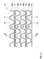
- Fig. 1 is a schematic representation of the view in the direction of flow the inlet side of a catalyst according to a first preferred embodiment reproduced the invention.
- the catalyst 10, the excerpt is shown, comprises a stack of flat sheets S1, .., S4 and corrugated Sheets CS1, .., CS4, which are arranged alternately in the stack and together are connected.
- the stack of sheets S1, .., S4 and CS1, .., CS4 forms the Structure of the catalyst 10.
- the corrugated sheets CS1, .., CS4 between adjacent flat sheets a variety of separate, parallel channels generated, of which in Fig. 1 four selected and arranged one above the other are designated by the reference symbols C1, .., C4.
- the corrugated sheets CS1, .., CS4 are very thin and typically have one Thickness of 0.05mm.
- the flat sheets S1, .., S4 are for good reasons Solid-state heat conduction, on the other hand, is preferably considerably thicker.
- the flat sheets S1, S3 and S2, S4 are practically identical in themselves (as seen in Fig. 2), but are stacked in a different one Arrangement installed.
- the entire catalyst 10 is from a certain one Number of units arranged one above the other, each unit consists of the sequence of sheets S1, CS2, S2, CS3 and thus a height of has two channel diameters.
- the catalytic coating 11, 12 required for the catalytic converter function is arranged in the form of strips extending in the flow direction FD (FIG. 2) on the flat sheets S1,... S4 in a specific configuration: the sheets, which have a total length L total have, are divided in the flow direction FD into two or more different sections 13, 14 which are alternately provided with catalytic coatings 11, 12 or have no catalytic coating at all.
- sections 13, 14 which are alternately provided with catalytic coatings 11, 12 or have no catalytic coating at all.
- the sheet is alternately on the upper side (catalytic coating 11) and on across width w across width w the underside (catalytic coating 12) so that the flat sheets S1, .., S4 are not provided with a catalytic coating on both sides at the same time.
- the sections provided with catalytic coatings 11, 12 are offset from one another (FIGS. 2, 3) such that the coatings occur alternately.
- the sheet S1 is coated in the first section 13 over the length L, while the sheet S2 in this section is uncoated.
- the sheet S1 is then uncoated, while the sheet S2 is coated.
- There are therefore certain channels in each section (marked with a (*) in FIG. 1 and also in FIG. 5) which do not have a catalytic coating 11, 12 in this section.
- FIGS. 1 and 3 show how the sheets CS2, S2 and CS3 are arranged on the first length L coated (the first section 13) in such a way that they form channels with a relatively large surface area, the uncoated walls of which are those of the catalytically active coatings 11, 12 absorb heat radiated on the plates S1 and S3 and dissipate it by convection in the respective channel.
- Fig. 3 clearly differentiates between the coated and uncoated channels in a section (13). In the following section (14), the sheets CS1, S1, CS2 and CS3, S3, CS4 form the uncoated channels, while the sheet S2 is catalytically active and radiates heat.
- the catalytic converter 10 comprises more than two sections 13, 14 with an alternating coating, because this improves the uniformity of the temperature and the fuel concentration within the catalytic converter 10.
- the flat sheets S1, ..., S4 each at the entrance and are uncoated at the outlet of the catalyst.
- This preferably shows uncoated area at the entrance a depth of approx. 2 to 5 mm and at the exit a depth of approx. 10-15 mm.
- this will result in a better mechanical Strength achieved in these areas, on the other hand you can use the catalyst better manufacture, since the flat sheets S1, ..., S4 better with the corrugated Have plates CS1, ..., CS4 welded.
- the uncoated serves at the outlet Additional area as radiation protection against a homogeneous flame or hot flame outside the catalyst.
- the catalyst structure shown has further advantages: On the one hand, the hot gases emerging from the catalyst are essential more uniform (i.e. with the same degree of chemical conversion to all channels) than with conventional catalyst configurations. Because one catalytic reactor is used in gas turbines where some of the fuel is burned homogeneously, this enables a more controllable and cleaner, i.e. combustion with lower NOx and CO contents downstream of the catalyst. On the other hand, there are those with the catalytic Coating 11, 12 provided sheets S1, .., S4 - as already mentioned above - relatively thick so that heat can be transferred upstream to (a) the cooling in the area of the coating and (b) the "light-off" in the improve upstream areas.
- the corrugated sheets CS1, ..., CS4 like the flat sheets S1, ..., S4 are coated in sections, here again for reasons of heat dissipation not on both sides of the corrugated sheets may have a coating surface at the same time.
- the sectioned coating of the corrugated and flat sheets should in turn be such that within channels C1, .., C4 the sections with the catalytic coatings 11, 12, 15, 16 each uncoated sections face each other.
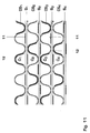
- FIG. 11 shows a schematic representation of the view in the direction of flow on the inlet side of a catalyst in such another Embodiment.
- Fig. 1 Embodiment in which uncoated corrugated sheets CS1, ..., CS4, 11, it can be clearly seen that the catalytic Coating area within the channels C1, ..., C4 clearly through the Use of corrugated sheet metal coated in sections is increased (Much more than 25% degree of coating) and therefore advantageous Sales of the catalyst can be increased.
- Fig. 11 also shows that in In contrast to the embodiment shown in Fig. 1 flat and wavy Sheets S1, .., S4, CS1, ..., CS4 used with approximately the same thickness can be.
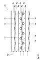
- FIG. 10 Another possible configuration is characterized by the fact that all levels Sheets S1, .., S4 are continuously coated in the same way as in FIG. 7 is shown. Instead of the alternating coating on adjacent sheets the simplified structure shown in FIG. 10 results. Since in this case the uncoated areas of the channels compared to those described above Variants are significantly reduced, cooling by heat radiation reduced and the main emphasis is on cooling by heat conduction and convective heat transfer.
- FIG. 12 shows a further embodiment variant analogous to FIG. 6.
- FIG. 12 shows a further embodiment variant analogous to FIG. 6.
- there is a larger coating area because every flat sheet S1, ..., S4 and not just every second is coated.
- the invention is not limited to the exemplary embodiments described limited.
Landscapes
- Chemical & Material Sciences (AREA)
- Engineering & Computer Science (AREA)
- Chemical Kinetics & Catalysis (AREA)
- Combustion & Propulsion (AREA)
- Mechanical Engineering (AREA)
- General Engineering & Computer Science (AREA)
- Health & Medical Sciences (AREA)
- Toxicology (AREA)
- Biomedical Technology (AREA)
- Environmental & Geological Engineering (AREA)
- Analytical Chemistry (AREA)
- General Chemical & Material Sciences (AREA)
- Oil, Petroleum & Natural Gas (AREA)
- Catalysts (AREA)
- Organic Low-Molecular-Weight Compounds And Preparation Thereof (AREA)
- Exhaust Gas Treatment By Means Of Catalyst (AREA)
Abstract
Description
Um den Umsatz zu erhöhen wird die Beschichtungsfläche vergrössert, indem gewellten Bleche ebenfalls abschnittsweise wie die ebenen Bleche katalytisch beschichtet sind.
- Fig. 1
- in einer schematisierten Darstellung die Sicht in Strömungsrichtung auf die Einlassseite eines Katalysators gemäss einem ersten bevorzugten Ausführungsbeispiel der Erfindung;
- Fig. 2
- die Draufsicht von oben auf verschiedene beschichtete und unbeschichtete Bleche des Katalysators nach Fig. 1;
- Fig. 3
- den Längsschnitt durch den Katalysator aus Fig. 1 entlang der Ebene III-III;
- Fig. 4
- eine zu Fig. 2 alternative Art der Beschichtung der Bleche eines Katalysators nach der Erfindung;
- Fig. 5
- in einer zu Fig. 1 vergleichbaren Darstellung ein Katalysator gemäss einem zweiten bevorzugten Ausführungsbeispiel der Erfindung mit einer Beschichtung gemäss Fig. 4;
- Fig. 6
- den Längsschnitt durch den Katalysator aus Fig. 5 entlang der Ebene VI-VI;
- Fig. 7
- eine weitere Möglichkeit der Beschichtung im Rahmen der Erfindung;
- Fig. 8
- in einer zu Fig. 2 vergleichbaren Darstellung verschiedene beschichtete und unbeschichtete Bleche des Katalysators gemäss einem weiteren bevorzugten Ausführungsbeispiel der Erfindung;
- Fig. 9
- den Längsschnitt durch einen Katalysator mit einer Beschichtung gemäss Fig. 8;
- Fig. 10
- die zu Fig. 1 und 5 vergleichbare Frontansicht eines Katalysators mit einer Beschichtung gemäss Fig. 7
- Fig. 11
- eine weitere Ausführungsvariante der Erfindung, bei welcher die gewellten Bleche zwischen den ebenen Blechen abschnittsweise beschichet sind und
- Fig. 12
- einen Längsschnitt durch den Katalysator analog zu Fig. 6 für eine weitere Ausführungsvariante, bei welcher alle ebenen Bleche abschnittsweise beschichtet sind.
- Die Wärmestrahlung absorbierende Oberfläche wird maximiert, so dass die Oberfläche der katalytischen Beschichtungen 11, 12 auf ein akzeptables Niveau heruntergekühlt wird.
- Alle Kanäle sind in wenigstens einem der Abschnitte mit einer katalytischen Beschichtung versehen, so dass eine gleichmässige Reduzierung des Brennstoffanteils zum Ausgang des Katalysators hin gewährleistet ist, wodurch eine homogene Zündung innerhalb des Katalysators verhindert wird.
- Eine noch höhere Gleichförmigkeit in allen Kanälen.
- Eine noch bessere Ableitung der Wärme aus den katalytisch beschichteten Inseln, da sich die Längen für die Wärmeleitung verringern (die Wärmeleitung ist umgekehrt proportional zum Durchmesser der Inseln).
- Sie ermöglicht eine Mischung zwischen den Kanälen, welche die Gleichförmigkeit von Temperatur und Brennstoffanteil weiter verbessert.
- Die Ausbildung von (laminaren) Randschichten entlang den katalytisch beschichteten Oberflächen wird wiederholt unterbrochen, wodurch sich der Reaktionsprozess aus einem Bereich mit diffusionskontrollierter Reaktion entfernt und damit die Oberflächentemperaturen reduziert werden. Die Länge Lcoated kann vorzugsweise von der gleichen Grössenordnung sein wie die Längen, über die sich die Randschichten entwickeln.
- Die Oberflächentemperatur der katalytisch beschichteten Bereiche wird unter der zur Deaktivierung führenden Temperatur gehalten.
- Das Risiko einer homogenen Zündung im Katalysator wird minimiert.
- Wärme wird in den (dickeren) Trägerplatten für die Beschichtung weitergeleitet; hierdurch wird der "light-off" verbessert und aufgrund der thermischen Trägheit die Stabilität des Systems erhöht.
- Druckverluste werden verringert und die Herstellbarkeit wird verbessert bzw. vereinfacht.
- Die aus dem Katalysator austretenden heissen Gase sind gleichmässiger durchmischt, so dass sich eine besser steuerbare homogene Verbrennung und eine sauberere Verbrennung mit geringeren NOx- und CO-Anteilen ergibt.
- 10,20,30
- Katalysator
- 11,12
- katalytische Beschichtung
- 13,14
- Abschnitt
- 15,16
- katalytische Beschichtung
- 17,18,19
- Wärmetransport
- C1,..,C4
- Kanal)
- CS1,..,CS4
- gewelltes Blech
- FD
- Strömungsrichtung
- S1,..,S4
- ebenes Blech
- w
- Breite der Bleche
- Lcoated
- beschichtete Länge
- Ltotal
- Länge (insgesamt)
Claims (23)
- Katalysator (10, 20, 30), welcher eine Mehrzahl von in einem Stapel übereinander angeordneten, voneinander beabstandeten, ebenen Blechen (S1,..,S4) umfasst, zwischen denen jeweils eine Mehrzahl von geraden, in Strömungsrichtung (FD) parallel verlaufenden Kanälen (C1,..,C4) ausgebildet sind, die von den ebenen Blechen (S1,..,S4) begrenzt werden, wobei die ebenen Bleche (S1,..,S4) mit katalytischen Beschichtungen (11, 12; 15, 16) versehen sind, dadurch gekennzeichnet, dass die ebenen Bleche (S1,..,S4) derart beschichtet sind, dass in allen Kanälen (C1,..,C4) katalytische Beschichtungen (11, 12; 15, 16) vorhanden sind, dass die katalytischen Beschichtungen (11, 12; 15, 16) auf vorgegebene Abschnitte (13, 14) der Kanäle (C1,..,C4) beschränkt sind, und dass innerhalb der Kanäle (C1,..,C4) den Abschnitten mit den katalytischen Beschichtungen (11, 12; 15, 16) zur Absorption der von den katalytischen Beschichtungen (11, 12; 15, 16) im Betrieb abgegebenen Wärmestrahlung jeweils unbeschichtete Abschnitte gegenüberliegen.
- Katalysator nach Anspruch 1, dadurch gekennzeichnet, dass die Kanäle (C1,..,C4) durch gewellte Bleche (CS1,..,CS4) gebildet werden, welche jeweils zwischen den ebenen Blechen (S1,..,S4) angeordnet und mit diesen verbunden sind, und dass die gewellten Bleche (CS1,..,CS4) unbeschichtet sind.
- Katalysator nach Anspruch 1, dadurch gekennzeichnet, dass die Kanäle (C1,...,C4) durch gewellte Bleche (CS1,...,CS4) gebildet werden, welche jeweils zwischen den ebenen Blechen (S1,...,S4) angeordnet und mit diesen verbunden sind, und dass die gewellten Bleche (CS1,..., CS4) zwecks Erhöhung des Umsatzes abschnittsweise derart katalytisch beschichtet sind, dass innerhalb der Kanäle (C1,..,C4) den Abschnitten mit den katalytischen Beschichtungen (11, 12; 15, 16) zur Absorption der von den katalytischen Beschichtungen (11, 12; 15, 16) im Betrieb abgegebenen Wärmestrahlung jeweils unbeschichtete Abschnitte gegenüberliegen.
- Katalysator nach einem der Ansprüche 1, 2 oder 3, dadurch gekennzeichnet, dass die katalytisch unbeschichteten Abschnitte der Kanäle (C1,...,C4) eine spezielle Beschichtung aufweisen, vorzugsweise zur Verbesserung der Absorption der Wärmestrahlung oder zur Begünstigung von Rekombinationsreaktionen von Radikalen.
- Katalysator nach einem der Ansprüche 1 bis 4, dadurch gekennzeichnet, dass die gewellten Bleche (CS1,..,CS4) eine Dicke von weniger als 0,1 mm, vorzugsweise etwa 0,05 mm, aufweisen, und dass die Dicke der ebenen Bleche (S1,..,S4) wesentlich grösser ist.
- Katalysator nach einem der Ansprüche 1 bis 4, dadurch gekennzeichnet, dass die Dicke der ebenen Bleche (S1,...,S4) und die Dicke der gewellten Bleche (CS1,...,CS4) etwa gleich gross ist.
- Katalysator nach einem der Ansprüche 1 bis 6, dadurch gekennzeichnet, dass die ebenen Bleche (S1, ...,S4) jeweils am Eintritt und am Austritt des Katalysators unbeschichtet sind.
- Katalysator nach Anspruch 7, dadurch gekennzeichnet, dass die unbeschichtete Fläche der Bleche (S1,...,S4) am Eintritt eine Tiefe von ca. 2 bis 5 mm und am Austritt eine Tiefe von ca. 10-15 mm aufweist.
- Katalysator nach einem der Ansprüche 1 bis 8, dadurch gekennzeichnet, dass alle Kanäle (C1,..C4) im wesentlichen denselben Querschnitt aufweisen.
- Katalysator nach einem der Ansprüche 1 bis 8, dadurch gekennzeichnet, dass die ebenen Bleche (S1,..,S4) in Strömungsrichtung (FD) eine Gesamtlänge (Ltotal) aufweisen, dass die Gesamtlänge (Ltotal) in eine gerade Anzahl von Abschnitten (13, 14) einer beschichteten Länge (Lcoated) unterteilt ist, und dass die einzelnen ebenen Bleche (S1,..,S4) über die Abfolge der Abschnitte (13, 14) alternierend mit katalytischen Beschichtungen (11, 12; 15, 16) versehen bzw. unbeschichtet sind, derart, dass bei im Stapel benachbarten ebenen Blechen die Abfolge der beschichteten und unbeschichteten Abschnitte (13, 14) jeweils um eine beschichtete Länge (Lcoated) in Strömungsrichtung (FD) gegeneinander verschoben ist.
- Katalysator nach Anspruch 10, dadurch gekennzeichnet, dass bei den ebenen Blechen (S1,..,S4) innerhalb der mit den katalytischen Beschichtungen (11, 12) versehenen Abschnitte (13, 14) die katalytische Beschichtung (11, 12) in Form von parallelen, sich in Strömungsrichtung (FD) erstreckenden, durchgehenden Streifen gleicher Breite vorliegt, welche über die Breite (w) der Bleche alternierend auf der Ober- und Unterseite des Bleches angeordnet sind, derart, dass das Blech immer nur auf einer Seite beschichtet ist.
- Katalysator nach Anspruch 11, dadurch gekennzeichnet, dass jedem der Kanäle (C1,..,C4) jeweils ein Streifen der katalytischen Beschichtungen (11, 12) zugeordnet ist.
- Katalysator nach Anspruch 10, dadurch gekennzeichnet, dass bei den ebenen Blechen (S1,..,S4) innerhalb der mit den katalytischen Beschichtungen (15, 16) versehenen Abschnitte (13, 14) die katalytische Beschichtung (15, 16) in Form von parallelen, sich in Strömungsrichtung (FD) erstreckenden Reihen von einzelnen, inselförmigen Bereichen gleicher Abmessungen vorliegt, welche Reihen über die Breite (w) der Bieche alternierend auf der Ober- und Unterseite des Bleches angeordnet sind, derart, dass das Blech immer nur auf einer Seite beschichtet ist.
- Katalysator nach Anspruch 13, dadurch gekennzeichnet, dass jedem der Kanäle (C1,..,C4) jeweils eine Reihe der inselförmigen katalytischen Beschichtungen (15, 16) zugeordnet ist.
- Katalysator nach einem der Ansprüche 1 bis 14, dadurch gekennzeichnet, dass der Katalysator (3) in Strömungsrichtung (FD) eine Gesamtlänge (Ltotal) aufweist, dass die Gesamtlänge (Ltotal) in eine gerade Anzahl von Abschnitten (13, 14) einer beschichteten Länge (Lcoated) unterteilt ist, und dass die einzelnen ebenen Bleche (S1,..,S4) sich jeweils nur über einen der Abschnitte (13, 14) erstrecken und mit katalytischen Beschichtungen (11, 12; 15, 16) versehen sind, derart, dass die im Stapel benachbarten ebenen Bleche bezüglich der Abschnitte (13, 14) jeweils auf Lücke angeordnet sind.
- Katalysator nach Anspruch 15, dadurch gekennzeichnet, dass die katalytische Beschichtung (11, 12) in Form von parallelen, sich in Strömungsrichtung (FD) erstreckenden, durchgehenden Streifen gleicher Breite vorliegt, welche über die Breite (w) der Bleche alternierend auf der Ober- und Unterseite des Bleches angeordnet sind, derart, dass das Blech immer nur auf einer Seite beschichtet ist.
- Katalysator nach Anspruch 16, dadurch gekennzeichnet, dass jedem der Kanäle (C1,..,C4) jeweils ein Streifen der katalytischen Beschichtungen (11, 12) zugeordnet ist.
- Katalysator nach Anspruch 15, dadurch gekennzeichnet, dass die katalytische Beschichtung (15, 16) in Form von parallelen, sich in Strömungsrichtung (FD) erstreckenden Reihen von einzelnen, inselförmigen Bereichen gleicherAbmessungen vorliegt, welche Reihen über die Breite (w) der Bleche alternierend auf der Ober- und Unterseite des Bleches angeordnet sind, derart, dass das Blech immer nur auf einer Seite beschichtet ist.
- Katalysator nach Anspruch 18, dadurch gekennzeichnet, dass jedem der Kanäle (C1,..,C4) jeweils eine Reihe der inselförmigen katalytischen Beschichtungen (15, 16) zugeordnet ist.
- Katalysator nach einem der Ansprüche 1 bis 8, dadurch gekennzeichnet, dass die ebenen Bleche (S1,..,S4) und gegebenenfalls die gewellten Bleche (CS1,...,CS4) über die Gesamtlänge (Ltotal) mit einer katalytischen Beschichtung (15, 16) in Form von parallelen, sich in Strömungsrichtung (FD) erstreckenden Reihen von einzelnen, inselförmigen Bereichen gleicher Abmessungen versehen sind, wobei die inselförmigen Bereiche innerhalb der Reihen und quer zu den Reihen alternierend auf der Ober- und Unterseite des Bleches angeordnet sind, derart, dass das Blech immer nur auf einer Seite beschichtet ist.
- Katalysator nach Anspruch 20, dadurch gekennzeichnet, dass jedem der Kanäle (C1,..,C4) jeweils wenigstens eine Reihe der inselförmigen katalytischen Beschichtungen (15, 16) zugeordnet ist.
- Katalysator nach einem der Ansprüche 1 bis 21, dadurch gekennzeichnet, dass der Katalysator für exothermischen Reaktionen verwendet wird, bei denen eine begleitende homogene Gasphasenreaktion zu vermeiden ist.
- Katalysator nach Anspruch 22, dadurch gekennzeichnet, dass der Katalysator für den Einsatz bei Gasturbinen verwendet wird.
Applications Claiming Priority (2)
| Application Number | Priority Date | Filing Date | Title |
|---|---|---|---|
| CH14682001 | 2001-08-08 | ||
| CH14682001 | 2001-08-08 |
Publications (4)
| Publication Number | Publication Date |
|---|---|
| EP1300555A2 true EP1300555A2 (de) | 2003-04-09 |
| EP1300555A3 EP1300555A3 (de) | 2003-11-26 |
| EP1300555A9 EP1300555A9 (de) | 2003-12-17 |
| EP1300555B1 EP1300555B1 (de) | 2005-12-07 |
Family
ID=4565502
Family Applications (1)
| Application Number | Title | Priority Date | Filing Date |
|---|---|---|---|
| EP02400034A Expired - Lifetime EP1300555B1 (de) | 2001-08-08 | 2002-07-29 | Katalysator |
Country Status (5)
| Country | Link |
|---|---|
| US (1) | US6982065B2 (de) |
| EP (1) | EP1300555B1 (de) |
| DE (1) | DE50205175D1 (de) |
| DK (1) | DK1300555T3 (de) |
| NO (1) | NO335152B1 (de) |
Cited By (4)
| Publication number | Priority date | Publication date | Assignee | Title |
|---|---|---|---|---|
| EP1527890A1 (de) | 2003-10-30 | 2005-05-04 | Dymo Corporation | Drucker |
| EP1529934A1 (de) * | 2003-11-05 | 2005-05-11 | Scambia Industrial Developments Aktiengesellschaft | Verfahren zur Herstellung eines Katalysatorkörpers und durch das Verfahren herstellbarer Katalysatorkörper |
| EP1721694A1 (de) * | 2005-05-11 | 2006-11-15 | Scambia Industrial Developments Aktiengesellschaft | Verfahren zur Herstellung mindestens eines Blechelements, Verfahren zur Herstellung mindestens eines Katalysatorkörpers, hergestelltes Blechelement sowie hergestellter Katalysatorkörper |
| WO2010122006A1 (de) * | 2009-04-22 | 2010-10-28 | Emitec Gesellschaft Für Emissionstechnologie Mbh | Verfahren zur herstellung eines beschichteten wabenkörpers |
Families Citing this family (5)
| Publication number | Priority date | Publication date | Assignee | Title |
|---|---|---|---|---|
| DE10329162A1 (de) * | 2003-06-27 | 2005-01-13 | Alstom Technology Ltd | Katalytischer Reaktor und zugehöriges Betriebsverfahren |
| DE102006026510B3 (de) * | 2006-06-06 | 2007-05-24 | Leinemann Gmbh & Co. Kg | Flammensperreinsatz und Verfahren zu seiner Herstellung |
| CN101939073B (zh) * | 2007-10-12 | 2014-08-27 | 陶氏环球技术公司 | 耐热冲击性改进的烟灰过滤器 |
| US10767859B2 (en) * | 2014-08-19 | 2020-09-08 | Adler Hot Oil Service, LLC | Wellhead gas heater |
| JP7454136B2 (ja) | 2020-12-23 | 2024-03-22 | スズキ株式会社 | 自動二輪車の排気装置及びその製造方法 |
Family Cites Families (13)
| Publication number | Priority date | Publication date | Assignee | Title |
|---|---|---|---|---|
| JPS59136140A (ja) * | 1983-01-25 | 1984-08-04 | Babcock Hitachi Kk | 燃焼用触媒体 |
| US4870824A (en) * | 1987-08-24 | 1989-10-03 | Westinghouse Electric Corp. | Passively cooled catalytic combustor for a stationary combustion turbine |
| US5346389A (en) * | 1989-02-24 | 1994-09-13 | W. R. Grace & Co.-Conn. | Combustion apparatus for high-temperature environment |
| DE4018704C2 (de) | 1990-06-12 | 1994-05-11 | Friedr Gustav Theis Kaltwalzwe | Verfahren zur Herstellung gewickelter und/oder geschichteter metallischer Katalysator-Träger |
| US5232357A (en) * | 1990-11-26 | 1993-08-03 | Catalytica, Inc. | Multistage process for combusting fuel mixtures using oxide catalysts in the hot stage |
| DE4112354A1 (de) * | 1991-04-16 | 1992-10-22 | Behr Gmbh & Co | Vorrichtung zum katalytischen entgiften von abgasen |
| US5328359A (en) * | 1992-05-19 | 1994-07-12 | W. R. Grace & Co.-Conn. | Ignition stage for a high temperature combustor |
| DE4307442A1 (de) * | 1993-03-10 | 1994-09-15 | Wolff Walsrode Ag | Mehrschichtige, gereckte, heißsiegelbare Polypropylenfolie |
| US5512250A (en) * | 1994-03-02 | 1996-04-30 | Catalytica, Inc. | Catalyst structure employing integral heat exchange |
| DE4418630A1 (de) * | 1994-05-27 | 1995-11-30 | Emitec Emissionstechnologie | Wabenkörper auf Blechlagen unterschiedlicher Vormaterialien |
| DE19519847C1 (de) * | 1995-05-31 | 1997-01-23 | Forschungszentrum Juelich Gmbh | Anodensubstrat für eine Hochtemperatur-Brennstoffzelle |
| US5791044A (en) | 1995-12-22 | 1998-08-11 | Engelhard Corporation | Assembly and method for catalytic converter structures |
| BR9909986A (pt) | 1998-04-28 | 2000-12-26 | Engelhard Corp | Catalisadores monolìticos e processo afim para a fabricação |
-
2001
- 2001-12-20 US US10/022,742 patent/US6982065B2/en not_active Expired - Fee Related
-
2002
- 2002-07-29 EP EP02400034A patent/EP1300555B1/de not_active Expired - Lifetime
- 2002-07-29 DK DK02400034T patent/DK1300555T3/da active
- 2002-07-29 DE DE50205175T patent/DE50205175D1/de not_active Expired - Lifetime
- 2002-08-07 NO NO20023733A patent/NO335152B1/no not_active IP Right Cessation
Cited By (6)
| Publication number | Priority date | Publication date | Assignee | Title |
|---|---|---|---|---|
| EP1527890A1 (de) | 2003-10-30 | 2005-05-04 | Dymo Corporation | Drucker |
| EP1529934A1 (de) * | 2003-11-05 | 2005-05-11 | Scambia Industrial Developments Aktiengesellschaft | Verfahren zur Herstellung eines Katalysatorkörpers und durch das Verfahren herstellbarer Katalysatorkörper |
| EP1721694A1 (de) * | 2005-05-11 | 2006-11-15 | Scambia Industrial Developments Aktiengesellschaft | Verfahren zur Herstellung mindestens eines Blechelements, Verfahren zur Herstellung mindestens eines Katalysatorkörpers, hergestelltes Blechelement sowie hergestellter Katalysatorkörper |
| WO2010122006A1 (de) * | 2009-04-22 | 2010-10-28 | Emitec Gesellschaft Für Emissionstechnologie Mbh | Verfahren zur herstellung eines beschichteten wabenkörpers |
| US8444741B2 (en) | 2009-04-22 | 2013-05-21 | Emitec Gesellschaft Fuer Emissionstechnologie Mbh | Coated honeycomb body and method for producing a coated honeycomb body |
| RU2536739C2 (ru) * | 2009-04-22 | 2014-12-27 | Эмитек Гезельшафт Фюр Эмиссионстехнологи Мбх | Способ изготовления снабженного покрытием сотового элемента |
Also Published As
| Publication number | Publication date |
|---|---|
| NO335152B1 (no) | 2014-10-06 |
| US20030031608A1 (en) | 2003-02-13 |
| DK1300555T3 (da) | 2006-04-18 |
| EP1300555B1 (de) | 2005-12-07 |
| EP1300555A3 (de) | 2003-11-26 |
| NO20023733D0 (no) | 2002-08-07 |
| US6982065B2 (en) | 2006-01-03 |
| DE50205175D1 (de) | 2006-01-12 |
| NO20023733L (no) | 2003-02-10 |
| EP1300555A9 (de) | 2003-12-17 |
Similar Documents
| Publication | Publication Date | Title |
|---|---|---|
| DE2733640C3 (de) | Matrix für einen katalytischen Reaktor zur Abgasreinigung bei Brennkraftmaschinen | |
| DE69330103T2 (de) | Verfahren zur Herstellung eines katalytischen Reaktors | |
| DE69534984T2 (de) | Katalytische Einheit und Abgasreinigungsvorrichtung | |
| EP0542775B1 (de) | Monolithischer metallischer wabenkörper mit variierender kanalzahl | |
| DE19680093B4 (de) | Wabenkörper mit von einem Fluid durchströmbaren Kanälen von unterschiedlichem Strömungswiderstand | |
| DE69800933T2 (de) | Wärmeaustauschelemente für luftvorwärmer und verfahren zu deren herstellung | |
| DE69718436T2 (de) | Trägerkörper für abgaskatalysatoren. | |
| EP0152560B1 (de) | Matrix für einen katalytischen Reaktor zur Abgasreinigung | |
| DE19808934A1 (de) | Katalysatorträger aus Metall | |
| DE60118029T2 (de) | Wärmetauscher mit gelöteten platten | |
| EP0484364A1 (de) | Wabenkörper mit internen anströmkanten, insbesondere katalysatorkörper für kraftfahrzeuge. | |
| DE102009015849A1 (de) | Wärmetauscher | |
| EP0458045A1 (de) | Metallträgermatrix für einen katalytischen Reaktor | |
| DE2450093A1 (de) | Waermetauscher | |
| EP0676534A1 (de) | Katalysatormittel für die katalytische Behandlung von Abgas, Katalysator und Verfahren zur Herstellung der Katalysatormittel | |
| DE19701169A1 (de) | Katalytischer Konverter | |
| DE2636671C2 (de) | Katalysatorträger | |
| EP1300555B1 (de) | Katalysator | |
| DE69835696T2 (de) | Katalysator zur abgasemissionskontrolle, katalysatorstruktur, verfahren zur herstellung derselben, verfahren und vorrichtung zur abgasemissionskontrolle | |
| DE60300811T2 (de) | Metallischer Katalysatorträgerkörper | |
| DE2856678C2 (de) | ||
| DE3923094C2 (de) | Katalysator-Trägerkörper | |
| DE2834358B2 (de) | Katalytischer Reaktor | |
| DE2529358A1 (de) | Waermetauscher | |
| EP0775808A1 (de) | Verfahren zur Herstellung eines Katalysatorkörpers für die katalytische Behandlung von Gas, Katalysatorkörper und Katalysator |
Legal Events
| Date | Code | Title | Description |
|---|---|---|---|
| PUAI | Public reference made under article 153(3) epc to a published international application that has entered the european phase |
Free format text: ORIGINAL CODE: 0009012 |
|
| AK | Designated contracting states |
Kind code of ref document: A2 Designated state(s): AT BE BG CH CY CZ DE DK EE ES FI FR GB GR IE IT LI LU MC NL PT SE SK TR |
|
| AX | Request for extension of the european patent |
Extension state: AL LT LV MK RO SI |
|
| PUAL | Search report despatched |
Free format text: ORIGINAL CODE: 0009013 |
|
| AK | Designated contracting states |
Kind code of ref document: A3 Designated state(s): AT BE BG CH CY CZ DE DK EE ES FI FR GB GR IE IT LI LU MC NL PT SE SK TR |
|
| AX | Request for extension of the european patent |
Extension state: AL LT LV MK RO SI |
|
| RAP1 | Party data changed (applicant data changed or rights of an application transferred) |
Owner name: ALSTOM TECHNOLOGY LTD |
|
| 17P | Request for examination filed |
Effective date: 20040515 |
|
| AKX | Designation fees paid |
Designated state(s): DE DK FR GB IT SE |
|
| 17Q | First examination report despatched |
Effective date: 20040806 |
|
| GRAP | Despatch of communication of intention to grant a patent |
Free format text: ORIGINAL CODE: EPIDOSNIGR1 |
|
| GRAS | Grant fee paid |
Free format text: ORIGINAL CODE: EPIDOSNIGR3 |
|
| GRAA | (expected) grant |
Free format text: ORIGINAL CODE: 0009210 |
|
| AK | Designated contracting states |
Kind code of ref document: B1 Designated state(s): DE DK FR GB IT SE |
|
| REG | Reference to a national code |
Ref country code: GB Ref legal event code: FG4D Free format text: NOT ENGLISH |
|
| REF | Corresponds to: |
Ref document number: 50205175 Country of ref document: DE Date of ref document: 20060112 Kind code of ref document: P |
|
| GBT | Gb: translation of ep patent filed (gb section 77(6)(a)/1977) |
Effective date: 20060222 |
|
| REG | Reference to a national code |
Ref country code: SE Ref legal event code: TRGR |
|
| REG | Reference to a national code |
Ref country code: DK Ref legal event code: T3 |
|
| ET | Fr: translation filed | ||
| PLBE | No opposition filed within time limit |
Free format text: ORIGINAL CODE: 0009261 |
|
| STAA | Information on the status of an ep patent application or granted ep patent |
Free format text: STATUS: NO OPPOSITION FILED WITHIN TIME LIMIT |
|
| 26N | No opposition filed |
Effective date: 20060908 |
|
| REG | Reference to a national code |
Ref country code: FR Ref legal event code: PLFP Year of fee payment: 14 |
|
| PGFP | Annual fee paid to national office [announced via postgrant information from national office to epo] |
Ref country code: FR Payment date: 20150626 Year of fee payment: 14 |
|
| PGFP | Annual fee paid to national office [announced via postgrant information from national office to epo] |
Ref country code: DK Payment date: 20150721 Year of fee payment: 14 Ref country code: GB Payment date: 20150721 Year of fee payment: 14 Ref country code: DE Payment date: 20150721 Year of fee payment: 14 |
|
| PGFP | Annual fee paid to national office [announced via postgrant information from national office to epo] |
Ref country code: SE Payment date: 20150721 Year of fee payment: 14 |
|
| PGFP | Annual fee paid to national office [announced via postgrant information from national office to epo] |
Ref country code: IT Payment date: 20150727 Year of fee payment: 14 |
|
| REG | Reference to a national code |
Ref country code: DE Ref legal event code: R082 Ref document number: 50205175 Country of ref document: DE Representative=s name: ROESLER, UWE, DIPL.-PHYS.UNIV., DE Ref country code: DE Ref legal event code: R081 Ref document number: 50205175 Country of ref document: DE Owner name: GENERAL ELECTRIC TECHNOLOGY GMBH, CH Free format text: FORMER OWNER: ALSTOM TECHNOLOGY LTD., BADEN, CH |
|
| REG | Reference to a national code |
Ref country code: FR Ref legal event code: CD Owner name: ALSTOM TECHNOLOGY LTD, CH Effective date: 20161110 |
|
| REG | Reference to a national code |
Ref country code: DE Ref legal event code: R119 Ref document number: 50205175 Country of ref document: DE |
|
| REG | Reference to a national code |
Ref country code: DK Ref legal event code: EBP Effective date: 20170131 |
|
| REG | Reference to a national code |
Ref country code: SE Ref legal event code: EUG |
|
| GBPC | Gb: european patent ceased through non-payment of renewal fee |
Effective date: 20160729 |
|
| PG25 | Lapsed in a contracting state [announced via postgrant information from national office to epo] |
Ref country code: SE Free format text: LAPSE BECAUSE OF NON-PAYMENT OF DUE FEES Effective date: 20160730 Ref country code: FR Free format text: LAPSE BECAUSE OF NON-PAYMENT OF DUE FEES Effective date: 20160801 Ref country code: DE Free format text: LAPSE BECAUSE OF NON-PAYMENT OF DUE FEES Effective date: 20170201 |
|
| REG | Reference to a national code |
Ref country code: FR Ref legal event code: ST Effective date: 20170331 |
|
| PG25 | Lapsed in a contracting state [announced via postgrant information from national office to epo] |
Ref country code: GB Free format text: LAPSE BECAUSE OF NON-PAYMENT OF DUE FEES Effective date: 20160729 |
|
| PG25 | Lapsed in a contracting state [announced via postgrant information from national office to epo] |
Ref country code: IT Free format text: LAPSE BECAUSE OF NON-PAYMENT OF DUE FEES Effective date: 20160729 |
|
| PG25 | Lapsed in a contracting state [announced via postgrant information from national office to epo] |
Ref country code: DK Free format text: LAPSE BECAUSE OF NON-PAYMENT OF DUE FEES Effective date: 20160731 |