EP1300543A1 - Système de forage avec élargisseur - Google Patents
Système de forage avec élargisseur Download PDFInfo
- Publication number
- EP1300543A1 EP1300543A1 EP01123939A EP01123939A EP1300543A1 EP 1300543 A1 EP1300543 A1 EP 1300543A1 EP 01123939 A EP01123939 A EP 01123939A EP 01123939 A EP01123939 A EP 01123939A EP 1300543 A1 EP1300543 A1 EP 1300543A1
- Authority
- EP
- European Patent Office
- Prior art keywords
- drill
- borehole
- head
- pipe
- drilling device
- Prior art date
- Legal status (The legal status is an assumption and is not a legal conclusion. Google has not performed a legal analysis and makes no representation as to the accuracy of the status listed.)
- Withdrawn
Links
- 238000005553 drilling Methods 0.000 title claims abstract description 79
- 238000009527 percussion Methods 0.000 claims abstract description 29
- 238000000034 method Methods 0.000 claims abstract description 19
- 239000000463 material Substances 0.000 claims description 13
- 238000013016 damping Methods 0.000 claims description 5
- 230000008878 coupling Effects 0.000 description 11
- 238000010168 coupling process Methods 0.000 description 11
- 238000005859 coupling reaction Methods 0.000 description 11
- XLYOFNOQVPJJNP-UHFFFAOYSA-N water Substances O XLYOFNOQVPJJNP-UHFFFAOYSA-N 0.000 description 8
- 229910000278 bentonite Inorganic materials 0.000 description 7
- 239000000440 bentonite Substances 0.000 description 7
- SVPXDRXYRYOSEX-UHFFFAOYSA-N bentoquatam Chemical compound O.O=[Si]=O.O=[Al]O[Al]=O SVPXDRXYRYOSEX-UHFFFAOYSA-N 0.000 description 7
- 230000005641 tunneling Effects 0.000 description 6
- 239000007788 liquid Substances 0.000 description 4
- 238000005520 cutting process Methods 0.000 description 3
- 239000012530 fluid Substances 0.000 description 3
- 239000002689 soil Substances 0.000 description 3
- 238000007664 blowing Methods 0.000 description 2
- 238000011010 flushing procedure Methods 0.000 description 2
- 239000000203 mixture Substances 0.000 description 2
- 238000005086 pumping Methods 0.000 description 2
- 239000000523 sample Substances 0.000 description 2
- 239000002131 composite material Substances 0.000 description 1
- 230000000694 effects Effects 0.000 description 1
- 238000005516 engineering process Methods 0.000 description 1
- 230000009969 flowable effect Effects 0.000 description 1
- 239000013505 freshwater Substances 0.000 description 1
- 238000003780 insertion Methods 0.000 description 1
- 230000037431 insertion Effects 0.000 description 1
- 238000004519 manufacturing process Methods 0.000 description 1
- 230000002093 peripheral effect Effects 0.000 description 1
- 239000011435 rock Substances 0.000 description 1
- 238000007789 sealing Methods 0.000 description 1
Images


Classifications
-
- E—FIXED CONSTRUCTIONS
- E21—EARTH OR ROCK DRILLING; MINING
- E21B—EARTH OR ROCK DRILLING; OBTAINING OIL, GAS, WATER, SOLUBLE OR MELTABLE MATERIALS OR A SLURRY OF MINERALS FROM WELLS
- E21B7/00—Special methods or apparatus for drilling
- E21B7/20—Driving or forcing casings or pipes into boreholes, e.g. sinking; Simultaneously drilling and casing boreholes
- E21B7/208—Driving or forcing casings or pipes into boreholes, e.g. sinking; Simultaneously drilling and casing boreholes using down-hole drives
-
- E—FIXED CONSTRUCTIONS
- E21—EARTH OR ROCK DRILLING; MINING
- E21B—EARTH OR ROCK DRILLING; OBTAINING OIL, GAS, WATER, SOLUBLE OR MELTABLE MATERIALS OR A SLURRY OF MINERALS FROM WELLS
- E21B21/00—Methods or apparatus for flushing boreholes, e.g. by use of exhaust air from motor
- E21B21/12—Methods or apparatus for flushing boreholes, e.g. by use of exhaust air from motor using drilling pipes with plural fluid passages, e.g. closed circulation systems
-
- E—FIXED CONSTRUCTIONS
- E21—EARTH OR ROCK DRILLING; MINING
- E21B—EARTH OR ROCK DRILLING; OBTAINING OIL, GAS, WATER, SOLUBLE OR MELTABLE MATERIALS OR A SLURRY OF MINERALS FROM WELLS
- E21B4/00—Drives for drilling, used in the borehole
- E21B4/06—Down-hole impacting means, e.g. hammers
- E21B4/14—Fluid operated hammers
-
- E—FIXED CONSTRUCTIONS
- E21—EARTH OR ROCK DRILLING; MINING
- E21B—EARTH OR ROCK DRILLING; OBTAINING OIL, GAS, WATER, SOLUBLE OR MELTABLE MATERIALS OR A SLURRY OF MINERALS FROM WELLS
- E21B7/00—Special methods or apparatus for drilling
- E21B7/28—Enlarging drilled holes, e.g. by counterboring
Definitions
- the invention relates to a drilling device for expanding an earth hole.
- the drilling device includes a drill head that holds a drill bit has, a percussion piston, which is driven by a drive medium and hits the drill bit, as well as a hollow drill pipe which the drill head is attached and through the cavity of the drive medium is led to the percussion piston.
- the invention further relates to a method for expanding an existing one Borehole where a drill head is inserted into the borehole hollow drill pipe is attached and pulled through the borehole, being on a drill bit of the drill head during drilling Percussion piston that is driven by a drive medium, which is fed through the hollow drill pipe.
- Such a drilling device which works according to the method mentioned, is described in American patent US 5,791,419.
- This one described drilling device is used to drill an existing Pipe in the ground and to replace this pipe with a new pipe.
- the Hollow drill pipe is first pushed through the pipe to be drilled. If it emerges at the end of the pipe to be drilled, the Drill head attached to the hollow drill pipe.
- the drill bit i.e. the surface of the drill head with the cutting edges or teeth, which the Removal of the material to be drilled is directed towards the drill pipe.
- Percussion piston within the drill head which is annular and surrounding the drill string can strike the back of a drill bit, who carries the drill bit.
- the drill bit is over a damping element axially movably attached to the drill head.
- the drive medium for actuating the percussion piston - usually Compressed air - becomes the drill head through the interior of the hollow drill pipe and headed to the percussion piston. After flowing through the channels in the Drilling head and driving the percussion piston flows the drive medium through a channel to the drill bit bit. From here it can be in the pipe to be renovated parallel to the drill pipe Flow through the opening of the pipe to be drilled.
- This backflow of the drive medium which if necessary Blows drilling material out of the borehole takes place in the annulus around the Drill pipe, which with a large radial distance to the to be renewed Pipe is guided.
- this drill head To drill the tube essentially parallel to effect its axis, this drill head must have a guide body and have centering body. If the drill pipe is through a clogged or an area of water to be renewed Pipe is guided, there is a risk that the backflow of the drive medium is hindered or interrupted.
- the object of the invention is to provide a method and an apparatus for the Extension drilling of the type mentioned in such a way that the undisturbed blowing out of the drive medium is ensured.
- Drill pipe is surrounded by a hollow outer pipe, which one encloses the annulus surrounding the drill pipe through which the drive medium is led out of the borehole.
- an annular second channel within a linkage designed as a double linkage created a channel separate from the environment in the borehole the drive medium fed into the borehole after driving the Percussion piston can flow through to lead out of the borehole to become.
- materials can be prevented from the soil surrounding the boom together with the drive medium be flushed out of the borehole. For example, if the hole runs below the water table, is through the outer drill pipe, through which the drive medium flows back, the amount of Water is reduced, which together with the drive medium from the borehole is blown out.
- the method according to the invention is preferably used to extend a Pilot drilling used, which is produced in the directional drilling process has been.
- Directional drilling is done behind a steerable directional drilling head usually a support tube is drawn into the borehole. simultaneously a support medium is supplied, which usually consists of water offset bentonite.
- the support tube which at Drilling a pilot hole with the directional drill head retracted is, preferably as an outer rod of the extension drilling device used. This support tube is flush with the borehole.
- the aqueous bentonite which surrounds the support tube, has a gelatinous Consistency on the axial movement of the support tube with very little Allows frictional resistance. However, it closes an annulus outside the linkage through which the drive medium could flow out.
- the support medium is blown out of the borehole.
- the drive medium can flow freely through the annulus together with the drilling material between the inner drill pipe and the outer pipe at the end of the Flow down the borehole.
- the drill pipe is used for extension drilling exerts a tensile force on the drill head, extends through the drill pipe preferably the drill head and is connected to the back.
- the percussion piston is preferably annular, that surrounds it Drill pipe and strikes the back of the drill bit of the drill head.
- the drill bit i.e. is the area that causes the soil to be removed on the side of the drill head facing away from the end of the drill pipe arranged.
- the drive medium is thus through the inner drill pipe, which extends through the drill head.
- At the end of the inner drill pipe is screwed on a cover that the inside of the drill pipe seals and the tensile force from the drill pipe in the Initiates drilling head.
- the drill head has a substantially cylindrical jacket Shape.
- a sleeve-shaped piston is displaceable in the drill head guided. Also run in the drill head and in the sealing cover Channels for the passage of the drive medium in the ring area in which the percussion piston is received.
- the drive medium flows through preferably pneumatic control means which control the piston movement cause and for years in connection with pneumatic deep hole hammers are known.
- the drill bit is also from a channel protrudes for the passage of the drive medium, which in the area of Drill bit opens.
- the drive medium is initially by the inner drill pipe and then through the drill head to the Removal-causing surface of the drill bit.
- Towards the front of the The drill bit has at least one entry opening in the outer rod, through which the drive medium directed into the base of the expansion hole can pass through.
- the drive medium mentioned is thus due to the overpressure together with the removed material (Drilling material) into the annular space between the outer rod and the inner drill rod flow in and transported out of the borehole through this annular space.
- a rotary movement on the drill string Transfer the drill bit.
- the inner drill pipe and the outer pipe preferably over one another engaging internal thread and external thread screwed together. Since the vibrations from the percussion piston are usually such Loosen screw connection is a rotary drive in the direction of the screw connection required to prevent unwanted screwing and loosening of the drill pipe to prevent.
- the rotary movement increases which is transmitted via the drill pipe, the removal rate the drill bit.
- the inner linkage and the outer linkage are particularly preferred attached to a common coupling element outside the borehole.
- the rotary movement is common via the coupling element transferred to the inner drill pipe and to the outer pipe.
- To the another is the drive medium via the coupling element inside of the inner drill pipe.
- the coupling element also has Outlet openings for the drive medium flowing out of the borehole on.
- the coupling element is preferably on a tunneling machine arranged, which has a linear drive, the tensile force on the Coupling element and via the coupling element on the inner drill pipe and transmits the outer linkage.
- the torque can be exerted on the drill bit either by the inner rod alone or only from the outer linkage or from both linkages at the same time be transmitted.
- the drill bit with the drill bit is elastic damped against the drill pipe. This reduces the transfer of the Impact forces of the percussion piston from the drill bit to the drill pipe.
- the essential part of the energy of the percussion piston for the Material removal via the drill bit into the end face of the drill bit initiated. Only a small percentage is transferred to the drill pipe, so that it is not overloaded.
- the drilling device At the rear end of the drill head in the pulling direction there is preferably a Connecting element attached to which a support tube is attached.
- a Connecting element attached to which a support tube is attached.
- the support tube of the first expansion hole which in many cases is the final one that has been drawn into the hole
- Forms useful pipe e.g. for the intake of fresh water, cabling etc.
- the support tube is preferably linearly through without rotational movement the borehole is pulled through and is therefore of the rotary motion decoupled from the drill pipe.
- the end face of the support tube drawn through the borehole is preferably closed via a head plate, which is part of the connecting element is.
- the head plate preferably has at least one Exit channel for a support medium, which through the support tube is brought into the borehole near the drill head.
- a support medium is - as already mentioned - preferably mixed with water Bentonite used, which has a gel-like consistency and one has low friction resistance, so that the retraction of the support tube is facilitated.
- the surface of the support tube head plate facing the drill pipe preferably has an oblique at least in the outer region of its circumference to the radial direction of the drill pipe surface extending in Direction tapered.
- the preferably conical surface the top plate causes the supporting fluid to be displaced into the peripheral Areas of the support tube.
- the new drilling device can be an inventive one Methods for widening an existing borehole are implemented, where a drill head is hollow on a hole drilled into the borehole Drill pipe attached and pulled through the borehole, taking on a drill bit of the drill head while drilling a percussion piston strikes, which is driven by a drive medium which by the hollow drill pipe is fed.
- the method according to the invention is particularly preferred for expansion used by pilot holes that are produced using the directional drilling method were.
- the directional drilling process becomes a steerable directional drilling head driven through the earth.
- the directional drill head is designed that it creates a borehole, the longitudinal axis of which in a certain direction is curved.
- the Direction of curvature can be varied. Should be drilled straight ahead the directional drilling head is continuously rotated around its longitudinal axis, so that the curvature of the borehole is even in all directions distributed and thus canceled.
- a directional drill head is installed according to the status technology with a directional drill pipe pushed through the borehole, wherein a support medium is introduced into the borehole, which is flush against the directional drill pipe. This directional drill pipe forms the outer linkage after completion of the pilot drilling for the drilling device according to the invention.
- the drilling capacity is preferably achieved by using a rotary actuator coupled to the drill head increased.
- the support tube preferably decoupled from the rotary movement of the drill pipe.
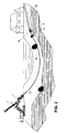
- FIG. 1 The mode of operation of directional drilling can be seen in FIG. 1.
- a tunneling machine 1 is used to create a pilot hole Direction drill head 2 by means of a directional drill pipe 3 in one Angle driven into the ground.
- the directional drill pipe 3 is on a rail-guided carriage of the tunneling machine 1 and is driven into the ground with a linear drive. After one Propulsion by a certain distance is applied to the directional drill pipe 3 a new section of the directional drill pipe 3 is added and the Carriage retracted to extend directional drill pipe 3 to advance further.
- the tunneling machine 1 also has a rotary drive 7, with which the directional drill pipe 3 rotated about its longitudinal axis and in a certain angular position can be locked. In this way can change the plane of the radius of curvature of the hole created in any Directions are inclined.
- the pilot hole can thus largely parallel to the surface of the earth in any direction. In particular can - as can be seen in Fig.
- Direction drilling head 2 rotated evenly around its axis.
- the support fluid will passed under high pressure in the directional drill pipe 3 and exits Rinsing nozzles in the directional drilling head 2. This will remove the material effected in the area of the directional drilling head 2.
- the bentonite in the Support fluid then lies in the annular gap between the Directional drill pipe 3 and the borehole. This will on the one hand produced borehole and on the other hand a fairly low-friction sliding film generates the resistance to propulsion of the directional drill pipe 3 reduced.
- a directional boring head 2 with integrated hammer is, for example, from the Document DE 199 46 587 A1 known.
- the above unpublished European patent application with the application number 01 201 167.2 shows a directional drill head 2 in which the directional drill pipe 3 is hollow and a blow rod leads over which blows from an outside Impact mechanism can be transferred to the directional drilling head 2.
- the directional drilling head 2 After completion of the pilot drilling, the directional drilling head 2, which has emerged from the exit opening of the bore from the directional drill pipe 3 removed.
- An extension drill head according to the invention can then be used 6 - hereinafter only called the drill head - on the hollow Directional drill pipe 3 according to the aforementioned European patent application attached, which is then through the pilot hole is pulled through.
- the linear drive is used for the tunneling machine to apply the tensile forces.
- the rotary drive 7 is used to to transmit a rotary movement to the drill head 6.
- At the end of the outer string 3 formed by the directional drill pipe near the Extension drill head 6 is still sensor 4 for position determination arranged.
- the outer rod 3 In the outer rod 3 is an inner drill pipe 8 inserted, through which on the one hand the rotational forces on the drill head 6 transmitted and on the other hand a drive medium 9 (see FIG. 4) Drill head 6 is passed.
- the drive medium 9 is usually compressed air, but can also consist of other suitable flowable media.
- a support tube 10 is connected to the free end of the drawn drilling head 6, which during the production of the extension bore the drill head 6 is drawn into the resulting borehole. Doing so a support medium 11 for producing the extension bore (cf. FIG. 3 and 4) introduced into the support tube 10. This is why it is in the making the extension bore, the pumping and mixing unit 5 for the Support medium 11 arranged near the location where the support tube 10 from the Borehole emerges.
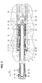
- the drill head 6 located in the borehole in an enlarged view Presentation.
- the drill head 6 comprises a drill bit 12 on its the drill pipe 8 facing end. Since the drill head 6 with the drill bit 12 by means of the drill pipe 8 through the borehole into a through an arrow shown in the direction X is pulled, is in the direction of pull X facing free end face of the drill bit 12, the drill bit 13, which the Material removal in the bottom of the borehole causes.
- a drive medium 9 is passed, which drives a percussion piston 14 on the opposite of the drill bit 13 lying back of the drill bit 12 strikes.
- a cover 15 is screwed on, the drill string 8th closes and transmits the tensile forces to the drill bit 13.
- an elastic damping element 17 wears. Against this damping element 17 is based on Intermediate piece 18 from the drill bit 12.
- the drill bit 12 itself is opposite the drill pipe 8 and preferably also the intermediate piece 18 held a certain distance in the axial direction. Consequently the strokes of the percussion piston 14, which are within the intermediate piece 18 of the drill head is arranged and surrounds the drill pipe 8, only introduced into the drill bit 13 and not into the drill pipe 8.
- Flow channels 19 arranged which the passage of the drive medium 9 through further flow channels 20, 21 of the drill head 6 through allows in the annular space 22 in which the percussion piston 14 is guided.
- the pneumatic control of the percussion piston 14 of a downhole hammer is the Well known to a person skilled in the art and is not described in more detail here.
- the drive medium 9 used for driving the percussion piston 14 flows through a plurality of flow channels 23 in the drill bit 12 to the latter in the pulling direction X front end face, which forms the drill bit 13.
- the Drive medium 9 has an overpressure compared to the atmosphere, so that it is from the area in front of the drill bit 13 together with the drill material 24 enters an annular inlet opening 25, which between the inner drill pipe 8 and the outer pipe 3 at a distance from Drill bit 13 is arranged.
- the drive medium 9 can then together with the cuttings 24 through the annular space between the drill pipe 8 and outer linkage 3 flow until it through outlet openings 26 on End of the outer rod 3 emerges outside the borehole.
- the outlet openings 26 are on a common coupling element 27 arranged, which both the inner drill pipe 8 and the outer pipe 3 wears. Via a ring seal 28 is a feed line 29 for the drive medium 9 connected to the coupling element 27.
- inlet channels 30, which open into the ring seal 28, make this possible Inflow of the drive medium 9 into the interior of the inner drill pipe 8th.
- the coupling element 27 is with the rotary drive 7 and the linear drive the tunneling machine 1 (see. Fig. 2) connected and transmits the train and Rotational forces on the inner drill pipe 8 and the outer pipe 3.
- the enlarged bore is preferably shared by one support tube 10 pulled through the borehole with the drill head 6 lined.
- the cap 15 is at the end of the drill pipe 8, a pull bell 31 fixedly connected via a roller bearing 32 is decoupled from the rotary movement of the drill head 6.
- a head plate 33 is connected to the pull bell 31.
- the support liquid 11 (consisting of a Bentonite / water mixture) into the borehole.
- the head plate 33 has a plurality of outflow channels 34 for the support liquid 11.
- the in the direction of pull X front surface of the head plate 33, which towards the bell 31 has a conical shape in order to displace the support liquid 11 in the area in front of the head plate 33 towards the wall of the borehole favor. So a lightly compacted bentonite layer between the Wall of the support tube 10 and the soil created, which due their gel-like consistency the friction between the support tube 10 and the ground reduced.
Landscapes
- Engineering & Computer Science (AREA)
- Life Sciences & Earth Sciences (AREA)
- Geology (AREA)
- Mining & Mineral Resources (AREA)
- Physics & Mathematics (AREA)
- Environmental & Geological Engineering (AREA)
- Fluid Mechanics (AREA)
- General Life Sciences & Earth Sciences (AREA)
- Geochemistry & Mineralogy (AREA)
- Mechanical Engineering (AREA)
- Earth Drilling (AREA)
Priority Applications (2)
| Application Number | Priority Date | Filing Date | Title |
|---|---|---|---|
| EP01123939A EP1300543A1 (fr) | 2001-10-08 | 2001-10-08 | Système de forage avec élargisseur |
| US10/252,727 US6808030B2 (en) | 2001-10-08 | 2002-09-23 | Enlargement drilling system |
Applications Claiming Priority (1)
| Application Number | Priority Date | Filing Date | Title |
|---|---|---|---|
| EP01123939A EP1300543A1 (fr) | 2001-10-08 | 2001-10-08 | Système de forage avec élargisseur |
Publications (1)
| Publication Number | Publication Date |
|---|---|
| EP1300543A1 true EP1300543A1 (fr) | 2003-04-09 |
Family
ID=8178875
Family Applications (1)
| Application Number | Title | Priority Date | Filing Date |
|---|---|---|---|
| EP01123939A Withdrawn EP1300543A1 (fr) | 2001-10-08 | 2001-10-08 | Système de forage avec élargisseur |
Country Status (2)
| Country | Link |
|---|---|
| US (1) | US6808030B2 (fr) |
| EP (1) | EP1300543A1 (fr) |
Cited By (2)
| Publication number | Priority date | Publication date | Assignee | Title |
|---|---|---|---|---|
| WO2010102741A3 (fr) * | 2009-03-11 | 2011-03-10 | Tracto-Technik Gmbh & Co. Kg | Procédé et système pour introduire un tuyau dans un trou dans la terre |
| CN109208580A (zh) * | 2018-10-26 | 2019-01-15 | 中国电建集团中南勘测设计研究院有限公司 | 一种孔口封闭器及钻灌装置 |
Families Citing this family (6)
| Publication number | Priority date | Publication date | Assignee | Title |
|---|---|---|---|---|
| IES20050621A2 (en) * | 2005-09-20 | 2006-11-15 | Minroc Techn Promotions Ltd | A percussion hammer for enlarging drilled holes |
| US7673706B2 (en) * | 2006-03-30 | 2010-03-09 | Sandvik Intellectual Property Ab | Down-the-hole hammer with pilot and method of enlarging a hole |
| US7699123B2 (en) * | 2007-06-04 | 2010-04-20 | Putnam Samuel W | Bore hole sleeve reaming apparatus and method |
| AU2016272983A1 (en) * | 2015-05-29 | 2017-12-14 | Herrenknecht Ag | System and method for laying underground cables or underground lines in the ground near the surface |
| AU2017324854A1 (en) * | 2016-09-06 | 2019-03-14 | Quanta Associates, L.P. | Pulling product lines underground under obstacles including water bodies |
| US11095101B2 (en) | 2016-09-06 | 2021-08-17 | Quanta Associates, L.P. | Repurposing pipeline for electrical cable |
Citations (5)
| Publication number | Priority date | Publication date | Assignee | Title |
|---|---|---|---|---|
| DE4225701C1 (de) * | 1992-08-04 | 1993-12-23 | Peter Rubak | Erdbohrgerät |
| US5375669A (en) * | 1993-02-12 | 1994-12-27 | Cherrington Corporation | Method and apparatus for cleaning a borehole |
| EP0763648A1 (fr) * | 1995-09-14 | 1997-03-19 | Rd Trenchless Ltd Oy | Dispositif et procédé de forage |
| DE19946587A1 (de) | 1999-09-29 | 2001-04-12 | Eurodrill Gmbh Consulting Engi | Vorrichtung zum Richtungsbohren |
| US20010006120A1 (en) * | 1999-12-03 | 2001-07-05 | Osamu Miyamoto | Multiple air hammer apparatus and excavating direction correcting method therefor |
Family Cites Families (36)
| Publication number | Priority date | Publication date | Assignee | Title |
|---|---|---|---|---|
| US2018007A (en) * | 1933-12-19 | 1935-10-22 | William G Brewster | Sidetracking tool |
| US2315629A (en) * | 1941-07-30 | 1943-04-06 | Bus Franklin L Le | Wall core scraper |
| US2684581A (en) * | 1951-11-06 | 1954-07-27 | John A Zublin | Flexible jointed drill pipe |
| US3797586A (en) * | 1971-12-20 | 1974-03-19 | Bell Telephone Labor Inc | Mole with decoupled nose and body |
| AT321206B (de) * | 1972-10-02 | 1975-03-25 | Boehler & Co Ag Geb | Bohrverfahren und Vorrichtung zu seiner Durchführung |
| US3894402A (en) * | 1974-07-19 | 1975-07-15 | Martin D Cherrington | Apparatus and method for emplacing a conduit along an underground arcuate path |
| US4043136A (en) * | 1975-07-14 | 1977-08-23 | Tidril Corporation | System and method for installing production casings |
| USRE32267E (en) * | 1979-09-24 | 1986-10-21 | Reading & Bates Construction Co. | Process for drilling underground arcuate paths and installing production casings, conduits, or flow pipes therein |
| US4362520A (en) * | 1980-05-12 | 1982-12-07 | Perry John C | Flexible enclosed shaft |
| DE3107973C2 (de) * | 1980-07-12 | 1982-12-02 | Preussag Ag, 3000 Hannover Und 1000 Berlin | Bohrwerkzeug zur Herstellung gekrümmt verlaufender Abschnitte von Tiefbohrungen |
| US4368786A (en) * | 1981-04-02 | 1983-01-18 | Cousins James E | Downhole drilling apparatus |
| US4476945A (en) * | 1983-02-10 | 1984-10-16 | Atlantic Richfield Company | Drainhold drilling |
| US4732223A (en) * | 1984-06-12 | 1988-03-22 | Universal Downhole Controls, Ltd. | Controllable downhole directional drilling tool |
| US4787463A (en) * | 1985-03-07 | 1988-11-29 | Flowmole Corporation | Method and apparatus for installment of underground utilities |
| US4880067A (en) * | 1988-02-17 | 1989-11-14 | Baroid Technology, Inc. | Apparatus for drilling a curved borehole |
| US4878547A (en) * | 1988-10-28 | 1989-11-07 | Ingersoll-Rand Company | Rock drilling apparatus |
| DE3905999C1 (fr) * | 1989-02-25 | 1990-01-04 | Bergwerksverband Gmbh, 4300 Essen, De | |
| SE466319B (sv) | 1989-03-07 | 1992-01-27 | Atlas Copco Constr & Mining | Taetningsanordning foer vaetskespolning vid slaaende bergborrning |
| BE1003502A6 (nl) * | 1989-04-28 | 1992-04-07 | Smet Marc Jozef Maria | Stuurbare boormol. |
| JPH0674713B2 (ja) * | 1989-08-02 | 1994-09-21 | 松坂貿易株式会社 | 既設管を新管と敷設替えする方法および装置 |
| US5238073A (en) * | 1991-04-04 | 1993-08-24 | Rear Ian G | Uphole hammer |
| US5265687A (en) * | 1992-05-15 | 1993-11-30 | Kidco Resources Ltd. | Drilling short radius curvature well bores |
| JPH06108770A (ja) | 1992-08-31 | 1994-04-19 | Sig (Schweiz Ind Ges) | ロックドリル用ドリル装置 |
| US5467834A (en) * | 1994-08-08 | 1995-11-21 | Maverick Tool Company | Method and apparatus for short radius drilling of curved boreholes |
| US5538092A (en) * | 1994-10-27 | 1996-07-23 | Ingersoll-Rand Company | Flexible drill pipe |
| US5542482A (en) * | 1994-11-01 | 1996-08-06 | Schlumberger Technology Corporation | Articulated directional drilling motor assembly |
| US5547031A (en) * | 1995-02-24 | 1996-08-20 | Amoco Corporation | Orientation control mechanism |
| DE19607365C5 (de) * | 1996-02-27 | 2004-07-08 | Tracto-Technik Paul Schmidt Spezialmaschinen | Verfahren zum Lenken eines Erdbohrgeräts und ein lenkbares Gerät zum Herstellen einer Erdbohrung |
| DE19612902C2 (de) | 1996-03-30 | 2000-05-11 | Tracto Technik | Verfahren zum Richtungsbohren und eine Vorrichtung zur Durchführung des Verfahrens |
| US5816345A (en) * | 1997-04-17 | 1998-10-06 | Keller; Carl E. | Horizontal drilling apparatus |
| US5961252A (en) * | 1997-10-20 | 1999-10-05 | Digital Control, Inc. | Underground utility installation tension monitoring arrangement and method |
| US6109832A (en) * | 1998-04-02 | 2000-08-29 | Lincoln; David A. | Ram burster and method for installing tubular casing underground |
| DE19817872C2 (de) * | 1998-04-22 | 2002-08-08 | Tracto Technik | Aufweitvorrichtung |
| AU3719300A (en) * | 1999-03-03 | 2000-10-04 | Earth Tool Company, Llc | Method and apparatus for directional boring |
| CA2314856C (fr) * | 1999-08-04 | 2009-04-14 | Bj Services Company | Systeme de guidage d'entree laterale |
| US6659198B2 (en) * | 2001-06-20 | 2003-12-09 | S & S Trust | Back reamer assembly |
-
2001
- 2001-10-08 EP EP01123939A patent/EP1300543A1/fr not_active Withdrawn
-
2002
- 2002-09-23 US US10/252,727 patent/US6808030B2/en not_active Expired - Fee Related
Patent Citations (6)
| Publication number | Priority date | Publication date | Assignee | Title |
|---|---|---|---|---|
| DE4225701C1 (de) * | 1992-08-04 | 1993-12-23 | Peter Rubak | Erdbohrgerät |
| US5375669A (en) * | 1993-02-12 | 1994-12-27 | Cherrington Corporation | Method and apparatus for cleaning a borehole |
| EP0763648A1 (fr) * | 1995-09-14 | 1997-03-19 | Rd Trenchless Ltd Oy | Dispositif et procédé de forage |
| US5791419A (en) | 1995-09-14 | 1998-08-11 | Rd Trenchless Ltd. Oy | Drilling apparatus for replacing underground pipes |
| DE19946587A1 (de) | 1999-09-29 | 2001-04-12 | Eurodrill Gmbh Consulting Engi | Vorrichtung zum Richtungsbohren |
| US20010006120A1 (en) * | 1999-12-03 | 2001-07-05 | Osamu Miyamoto | Multiple air hammer apparatus and excavating direction correcting method therefor |
Cited By (6)
| Publication number | Priority date | Publication date | Assignee | Title |
|---|---|---|---|---|
| WO2010102741A3 (fr) * | 2009-03-11 | 2011-03-10 | Tracto-Technik Gmbh & Co. Kg | Procédé et système pour introduire un tuyau dans un trou dans la terre |
| GB2483376A (en) * | 2009-03-11 | 2012-03-07 | Tracto Technik | Method and system for inserting a tube into a borehole in the soil |
| GB2483376B (en) * | 2009-03-11 | 2013-03-20 | Tracto Technik | Method and system for inserting a tube into an undergound borehole |
| US9074423B2 (en) | 2009-03-11 | 2015-07-07 | Tracto-Technik Gmbh & Co. | Method and system for inserting a pipe into an underground borehole |
| CN109208580A (zh) * | 2018-10-26 | 2019-01-15 | 中国电建集团中南勘测设计研究院有限公司 | 一种孔口封闭器及钻灌装置 |
| CN109208580B (zh) * | 2018-10-26 | 2023-11-07 | 中国电建集团中南勘测设计研究院有限公司 | 一种孔口封闭器及钻灌装置 |
Also Published As
| Publication number | Publication date |
|---|---|
| US20030066684A1 (en) | 2003-04-10 |
| US6808030B2 (en) | 2004-10-26 |
Similar Documents
| Publication | Publication Date | Title |
|---|---|---|
| DE3114612C2 (de) | Bohrvorrichtung für Hartgestein | |
| DE2854461A1 (de) | Ringbohrhammer | |
| EP1213441B1 (fr) | Système de forage | |
| DE4433533C1 (de) | Rammbohrvorrichtung | |
| DE2924393A1 (de) | Bohrvorrichtung zum ueberlagerungsbohren | |
| EP2505762A2 (fr) | Dispositif de forage et procédé de forage horizontal | |
| DE2309570A1 (de) | Bohrgeraet und bohrstrang-einsatzanordnung | |
| DE1533644C3 (de) | Verfahren und Vorrichtung zum annähernd waagerechten Durchbohren von Dämmen aus Erd- oder Gesteinsschichten | |
| EP2863003A2 (fr) | Outil et dispositif d'agrandissement d'un passage existant dans le sol | |
| EP0548588A1 (fr) | Dispositif pour réaliser des forages dans le sol | |
| CH683016A5 (de) | Verfahren zum Aufweiten eines Bohrloches und Aufweitgerät. | |
| EP0293584B1 (fr) | Dispositif de forage pour méthode de forage par injection à haute pression | |
| EP0860638B1 (fr) | Dispositif et procédé de pose de tubes céramiques sans excavation | |
| DE4122350A1 (de) | Verfahren zur richtungssteuerung eines erdbohrgeraetes sowie vorrichtung zur herstellung von erdbohrungen | |
| DE19652530C2 (de) | Imlochhammer | |
| EP1300543A1 (fr) | Système de forage avec élargisseur | |
| EP2900895B1 (fr) | Dispositif et procédé de pose d'une canalisation dans un trou de forage | |
| DE4142733C2 (de) | Bohrverfahren und Einrichtung zur Ausübung des Verfahrens | |
| DE2924392C2 (de) | Bohrvorrichtung zum Überlagerungsbohren | |
| AT393292B (de) | Vorrichtung zur herstellung von durch zugabe von binde- oder abdichtemitteln verdichteten bodenabschnitten | |
| EP0358786A1 (fr) | Dispositif de forage superposé | |
| DE2642014A1 (de) | Anschlusstueck fuer bohrmeissel | |
| DE3926787C2 (de) | Verfahren und Vorrichtung zum Einbringen und Verankern eines Zugpfahls | |
| DE19946587A1 (de) | Vorrichtung zum Richtungsbohren | |
| DE2025439C3 (de) | Versenkhammer-Bohrgerät |
Legal Events
| Date | Code | Title | Description |
|---|---|---|---|
| PUAI | Public reference made under article 153(3) epc to a published international application that has entered the european phase |
Free format text: ORIGINAL CODE: 0009012 |
|
| AK | Designated contracting states |
Kind code of ref document: A1 Designated state(s): AT BE CH CY DE DK ES FI FR GB GR IE IT LI LU MC NL PT SE TR Designated state(s): AT BE CH CY DE DK ES FI FR GB GR IE IT LI LU MC NL PT SE TR |
|
| AX | Request for extension of the european patent |
Extension state: AL LT LV MK RO SI |
|
| AKX | Designation fees paid | ||
| 17P | Request for examination filed |
Effective date: 20031202 |
|
| RBV | Designated contracting states (corrected) |
Designated state(s): DE NL |
|
| REG | Reference to a national code |
Ref country code: DE Ref legal event code: 8566 |
|
| 17Q | First examination report despatched |
Effective date: 20040205 |
|
| GRAP | Despatch of communication of intention to grant a patent |
Free format text: ORIGINAL CODE: EPIDOSNIGR1 |
|
| GRAS | Grant fee paid |
Free format text: ORIGINAL CODE: EPIDOSNIGR3 |
|
| STAA | Information on the status of an ep patent application or granted ep patent |
Free format text: STATUS: THE APPLICATION IS DEEMED TO BE WITHDRAWN |
|
| 18D | Application deemed to be withdrawn |
Effective date: 20080503 |