EP1300367A2 - Small installation for the treatment of wastewater - Google Patents
Small installation for the treatment of wastewater Download PDFInfo
- Publication number
- EP1300367A2 EP1300367A2 EP02022120A EP02022120A EP1300367A2 EP 1300367 A2 EP1300367 A2 EP 1300367A2 EP 02022120 A EP02022120 A EP 02022120A EP 02022120 A EP02022120 A EP 02022120A EP 1300367 A2 EP1300367 A2 EP 1300367A2
- Authority
- EP
- European Patent Office
- Prior art keywords
- chamber
- clarification chamber
- water
- primary
- pump
- Prior art date
- Legal status (The legal status is an assumption and is not a legal conclusion. Google has not performed a legal analysis and makes no representation as to the accuracy of the status listed.)
- Withdrawn
Links
Images
Classifications
-
- C—CHEMISTRY; METALLURGY
- C02—TREATMENT OF WATER, WASTE WATER, SEWAGE, OR SLUDGE
- C02F—TREATMENT OF WATER, WASTE WATER, SEWAGE, OR SLUDGE
- C02F3/00—Biological treatment of water, waste water, or sewage
- C02F3/02—Aerobic processes
- C02F3/12—Activated sludge processes
- C02F3/1236—Particular type of activated sludge installations
- C02F3/1242—Small compact installations for use in homes, apartment blocks, hotels or the like
- C02F3/1247—Small compact installations for use in homes, apartment blocks, hotels or the like comprising circular tanks with elements, e.g. decanters, aeration basins, in the form of segments, crowns or sectors
-
- Y—GENERAL TAGGING OF NEW TECHNOLOGICAL DEVELOPMENTS; GENERAL TAGGING OF CROSS-SECTIONAL TECHNOLOGIES SPANNING OVER SEVERAL SECTIONS OF THE IPC; TECHNICAL SUBJECTS COVERED BY FORMER USPC CROSS-REFERENCE ART COLLECTIONS [XRACs] AND DIGESTS
- Y02—TECHNOLOGIES OR APPLICATIONS FOR MITIGATION OR ADAPTATION AGAINST CLIMATE CHANGE
- Y02A—TECHNOLOGIES FOR ADAPTATION TO CLIMATE CHANGE
- Y02A20/00—Water conservation; Efficient water supply; Efficient water use
- Y02A20/20—Controlling water pollution; Waste water treatment
- Y02A20/208—Off-grid powered water treatment
-
- Y—GENERAL TAGGING OF NEW TECHNOLOGICAL DEVELOPMENTS; GENERAL TAGGING OF CROSS-SECTIONAL TECHNOLOGIES SPANNING OVER SEVERAL SECTIONS OF THE IPC; TECHNICAL SUBJECTS COVERED BY FORMER USPC CROSS-REFERENCE ART COLLECTIONS [XRACs] AND DIGESTS
- Y02—TECHNOLOGIES OR APPLICATIONS FOR MITIGATION OR ADAPTATION AGAINST CLIMATE CHANGE
- Y02W—CLIMATE CHANGE MITIGATION TECHNOLOGIES RELATED TO WASTEWATER TREATMENT OR WASTE MANAGEMENT
- Y02W10/00—Technologies for wastewater treatment
- Y02W10/10—Biological treatment of water, waste water, or sewage
Abstract
Description
Die Erfindung betrifft eine Vorrichtung zur Behandlung von Abwasser in einer Mehrkammer-Kleinkläranlage mit wenigstens je einer Vorklärkammer und einer Klärkammer, die durch eine Trennwand getrennt sind, mit einem Belüfter innerhalb der Klärkammer sowie Pumpeinrichtungen zur Überführung von Schmutzwasser von der Vorklärkammer in die Klärkammer sowie zur Rückführung von Überschußschlamm von der Klärkammer in die Vorklärkammer.The invention relates to a device for treating waste water in one Multi-chamber small wastewater treatment plant with at least one pre-treatment chamber and one Clarification chamber, which are separated by a partition, with an aerator inside the clarification chamber and pumping devices for transferring dirty water from the primary clarifier to the clarifier and for the return of Excess sludge from the clarifier to the primary clarifier.
Es ist bekannt, Mehrkammer-Kläranlagen, insbesondere solche mit Dreikammer-Behältern, mit verhältnismäßig wenigen Aggregaten für einen wirksamen Klärbetrieb auszurüsten. Ein Beispiel einer derartigen Anlage wird in der DE 200 20 795 U1 beschrieben. Im Interesse einer effizienten Steuerung des Klärvorganges ist eine relativ genaue Kontrolle des Transports der durch die Kläranlage hindurchgeführten Wassermengen notwendig. Zu diesem Zweck wird zum einen eine Klarwasser-Entnahmepumpe und im übrigen ein Belüfter innerhalb der Klärkammer benötigt. Ferner ist es notwendig, zum einen Schmutzwasser aus der Vorklärkammer in die Klärkammer zu überführen und zum anderen überschüssigen Schlamm aus der Klärkammer oder Behandlungsgrube zurück in die Vorklärkammer zu transportieren. Dies würde maximal zwei weitere Förderpumpen erfordern.It is known to use multi-chamber wastewater treatment plants, especially those with three-chamber tanks, with relatively few units for an effective one Equip wastewater treatment plant. An example of such a system is in DE 200 20 795 U1. In the interest of efficient control of the clarification process is a relatively precise control of the transport through the treatment plant quantities of water passed through it. For this purpose a clear water extraction pump and an aerator inside the clarification chamber. Furthermore, it is necessary, on the one hand, dirty water to transfer from the pre-clarification chamber into the clarification chamber and to the other excess sludge from the clarifier or treatment pit to be transported into the primary clarifier. This would be a maximum of two more feed pumps require.
In dem eingangs genannten Gebrauchsmuster wird jedoch eine Lösung beschrieben, bei der mit Hilfe nur einer Pumpe zum einen Klärschlamm aus der Klärkammer zurück in die Vorklärkammer transportiert und zum anderen Schmutzwasser aus der Vorklärkammer in die Klärkammer gebracht werden kann. Dies geschieht mit Hilfe einer in der Klärkammer angeordneten Pumpe, die eine über die Trennwand zwischen den Kammern hinweggeführte Ausgangsleitung aufweist, über die überschüssiger Schlamm aus der Klärkammer zurück in die Vorklärkammer transportiert wird. Wird die Pumpe anschließend abgeschaltet, so wird aufgrund des niedrigeren Wasserspiegels in der Klärkammer nach dem Prinzip der kommunizierenden Röhren Schmutzwasser von der Vorklärkammer in die Klärkammer gezogen. However, a solution is described in the utility model mentioned at the beginning, where with the help of only one pump sewage sludge from the Clarification chamber transported back to the primary clarification chamber and to the other Dirty water from the primary clarification chamber are brought into the clarification chamber can. This is done with the help of a pump arranged in the clarification chamber, the one outlet line led across the partition between the chambers has excess sludge back from the clarifier is transported into the clarifier. If the pump is then switched off, because of the lower water level in the clarification chamber According to the principle of communicating pipes, dirty water from the primary clarification chamber drawn into the clarifier.
An der Unterseite der Pumpe befindet sich eine nach unten offene Schale, durch die Luftblasen eingefangen werden, die von der unterhalb der Pumpe angeordneten Belüftung innerhalb der Klärkammer aufsteigen. Diese Luftblasen sammeln sich in der Schale und gelangen in die Ausgangsleitung, die über die Trennwand hinweg verläuft, bis sich hier so viel Luft angesammelt hat, daß die Saugwirkung unterbrochen wird. Auf diese Weise läßt sich die Überführung von Schmutzwasser aus der Vorklärkammer in die Klärkammer beenden. Eine Einschaltung der Belüftung zu einem im einzelnen zu ermittelnden und in der Pumpensteuerung festzulegenden Zeitpunkt und über einen ebenfalls zu ermittelnden Zeitraum kann also zur Steuerung des Schmutzwassertransports genutzt werden, ohne daß ein aufwendiges Ventilsystem oder sogar eine zweite Pumpe notwendig ist. Mit nur einer Pumpe können in einfacher Weise die beiden Ströme von der Klärkammer in die Vorklärkammer und von der Vorklärkammer in die Klärkammer gesteuert werden.At the bottom of the pump there is a bowl open through the air bubbles are trapped by those located below the pump Vent the ventilation inside the clarification chamber. Collect these air bubbles itself in the shell and get into the outlet pipe that goes over the partition runs away until so much air has accumulated here that the suction effect is interrupted. In this way, the transfer of End dirty water from the primary clarification chamber into the clarification chamber. An engagement ventilation to one to be determined in detail and in the pump control time to be determined and also to be determined Period can therefore be used to control the transport of dirty water be without a complex valve system or even a second pump necessary is. With just one pump, the two flows can easily from the clarification chamber to the primary clarification chamber and from the primary clarification chamber to the clarification chamber can be controlled.
Diese bekannte Lösung stellt zwar eine erhebliche Vereinfachung gegenüber dem früheren Stand der Technik dar, hat jedoch nach wie vor einige Nachteile.This known solution contrasts with a considerable simplification the prior art, however, still has some disadvantages.
Zum einen ist es notwendig, die gesamte Kläranlage bei Inbetriebnahme mit sauberem Frischwasser aufzufüllen, um eine Füllung der Verbindungsleitung zu gewährleisten und andererseits ein Leerlaufen der Klärkammer unterhalb des Pumpniveaus zu verhindern. Zum anderen werden die vorhandenen Volumina der einzelnen Kammern nur ungenügend ausgenutzt. Die Klärkammer kann nie vollständig gefüllt werden, da für den Transport des Wassers aus der Vorklärkammer ein deutlicher Höhenunterschied notwendig ist. Das Befüllen der Klärkammer erfolgt nur sehr langsam, da hier nur die Schwerkraftwirkung der Wassersäule zur Verfügung steht. Bei sehr unregelmäßigem Zufluß kann daher sogar eine zusätzliche Pumpe notwendig sein, die gewährleistet, daß stets eine gewisse Abwassermenge in die Klärkammer gelangt.On the one hand, it is necessary to use the entire wastewater treatment plant when commissioning fill up with fresh water to fill the connecting pipe ensure and on the other hand an empty running of the clarification chamber below the To prevent pump levels. On the other hand, the existing volumes insufficient use of the individual chambers. The clarifier can never be completely filled, as for the transport of water from the primary clarification chamber a clear difference in height is necessary. Filling the clarifier takes place very slowly, since here only the gravitational effect of the water column is available. If the inflow is very irregular, it can even an additional pump may be necessary, which ensures that there is always a certain Amount of waste water reaches the clarification chamber.
Der Erfindung liegt daher die Aufgabe zugrunde, eine Klärvorrichtung der obigen Art zu schaffen, die eine wirksamere und raschere Durchführung des Klärvorganges gestattet, ohne daß zusätzliche technische Aggregate erforderlich sind. The invention is therefore based on the object, a clarifying device of the above Way of creating a more effective and faster implementation of the clarification process permitted without the need for additional technical units are.
Diese Aufgabe wird erfindungsgemäß bei einer Vorrichtung der obigen Art dadurch gelöst, daß in der Vorklärkammer eine Pumpe zur Überführung von Schmutzwasser in die Klärkammer durch eine über die Trennwand hinweg in die Klärkammer verlaufende Leitung vorgesehen ist, daß am unteren Ende der Leitung in der Klärkammer eine nach unten offene Auffangschale vorgesehen ist und daß der Belüfter derart angeordnet ist, daß er unterhalb der Auffangschale ein Wasser-Luft-Gemisch erzeugt.This object is achieved according to the invention in a device of the above type solved that in the pre-clarification chamber a pump for transferring Dirty water into the clarification chamber through a across the partition the clarifying chamber running line is provided that at the lower end of the Line in the clarification chamber a downwardly open drip tray is provided and that the aerator is arranged so that it is below the drip tray creates a water-air mixture.
In diesem Falle erfolgt die Zwangsförderung des Schmutzwassers aus der Vorklärkammer in die Klärkammer mit größerer Geschwindigkeit, als bei dem zuvor beschriebenen System, das auf die Schwerkraftwirkung angewiesen ist. Dies ist wesentlich, da in dieser Richtung eine größere Fördergeschwindigkeit notwendig ist als bei der Rückführung der begrenzten Menge des Überschußschlammes. Dies geschieht nach der vorliegenden Erfindung nach dem System der kommunizierenden Röhren, nachdem bei gefüllter Leitung am Ende eines Pumpvorganges aus der über den Wasserspiegel der Vorklärkammer hinaus gefüllten Klärkammer in Richtung der Vorklärkammer eine Sogwirkung ausgeübt wird. Grundsätzlich ist es möglich, die Klärkammer bis zu einem nahezu beliebigen Niveau zu füllen. Es ist z. B. möglich, die Kläranlage bis zum Erreichen eines maximalen Niveaus in der Klärkammer in einem Sparbetrieb laufen zu lassen und danach erst den eigentlichen Reinigungsbetrieb zu starten. Durch Verwendung der Pumpe auf der Seite der Vorklärkammer ist ein gezieltes und rasches Füllen der Klärkammer stets gewährleistet. Die Vorklärkammer kann bei unregelmäßigem Zufluß als Pufferbecken benutzt werden, aus dem die Klärkammer mit Hilfe der Pumpe in Verbindung mit einer geeigneten Steuerung gezielt befüllt werden kann. Da die aus der Vorklärkammer ausgepumpte Wassermenge größer sein kann, als es bei einem einfachen Niveauausgleich möglich wäre, ergibt sich als weiterer Vorteil eine beträchtliche Vergrößerung des Puffervolumens in der Vorklärkammer.In this case, the dirty water is forced out of the pre-clarification chamber into the clarifier at a higher speed than the one before described system that relies on the action of gravity. This is essential, since a higher conveying speed is necessary in this direction than returning the limited amount of excess sludge. According to the present invention, this is done according to the system of communicating Tubing after the line is filled at the end of a pumping process from the clarification chamber filled above the water level in the primary clarification chamber a suction effect is exerted in the direction of the primary clarification chamber. Basically, it is possible to close the clarification chamber to almost any Fill level. It is Z. B. possible, the sewage treatment plant until reaching a operating maximum levels in the clarifier in an economy mode and only then start the actual cleaning operation. By using The pump on the side of the pre-clarification chamber is targeted and quick Filling the clarifier always guaranteed. The pre-clarifier can be irregular Inflow can be used as a buffer tank from which the clarification chamber with the help of the pump in connection with a suitable control system can be. Because the amount of water pumped out of the primary clarifier is greater than it would be possible with a simple level compensation Another advantage is a considerable increase in the buffer volume the pre-clarification chamber.
Neben diesen Vorteilen bietet die erfindungsgemäß vorgesehene Pumpe den weiteren Vorteil, daß sie zugleich zur gesteuerten Rückführung des Überschußschlamms aus der Klärkammer in die Vorklärkammer verwendet werden kann. Da die Ausgangsleitung der Pumpe in die Klärkammer eintaucht, kann das Wasser bzw. der Überschußschlamm aus der Klärkammer nach dem Abschalten des Pumpvorganges nach dem Prinzip der kommunizierenden Röhren in die Vorklärkammer zurücklaufen. In addition to these advantages, the pump provided according to the invention offers the further Advantage that they also for the controlled return of the excess sludge can be used from the clarifier to the primary clarifier. Since the pump outlet line is immersed in the clarification chamber, the water can or the excess sludge from the clarification chamber after switching off the Pumping process according to the principle of communicating tubes into the primary clarification chamber running back.
Erfindungsgemäß ist an der Austrittsöffnung der Leitung innerhalb der Klärkammer eine nach unten offene Schale vorgesehen, die die Eintrittsöffnung der Leitung umgibt, aber freiläßt. Da der Tauchbelüfter Luft in den Bereich unterhalb der Schale drückt, sammeln sich die vom Tauchbelüfter abgegebenen Luftblasen in der Schale und damit auch in der Leitung. Sobald sich hier ein ausreichend großes Luftpolster gebildet hat, wird die Saugwirkung in Richtung Vorklärkammer unterbrochen.According to the invention is at the outlet opening of the line within the clarification chamber a downwardly open shell is provided, which the inlet opening of the Line surrounds, but leaves free. Because the submersible aerator air is in the area below the shell presses, the air bubbles emitted by the submersible aerator collect in the shell and thus also in the line. Once there is a sufficient has formed a large air cushion, the suction effect in the direction of the primary clarification chamber interrupted.
Die zugehörige Steuerung kann so ausgelegt werden, daß zu Beginn eines Klär-Zyklus Schmutzwasser aus der Vorklärkammer in die Klärkammer überführt wird. Wird die Pumpe jetzt abgeschaltet, so fließt ein Wasser-Schlamm-Gemisch aus der Klärkammer zurück in die Vorklärkammer. Dieser Rückstrom kann in der beschriebenen Weise unterbrochen werden, wenn der Belüfter über ein vorprogrammiertes Zeitintervall eingeschaltet oder auch für den weiteren Klärvorgang in Betrieb gesetzt wird. Sobald sich ein ausreichendes Luftpolster in der Ausgangsleitung der Pumpe gesammelt hat, ist der Rückstrom beendet. Der Klärvorgang kann fortgesetzt werden.The associated control can be designed so that at the beginning of a clarification cycle Dirty water is transferred from the primary clarifier to the clarifier becomes. If the pump is now switched off, a water-sludge mixture flows from the clarifier back to the primary clarifier. This backflow can be in be interrupted as described if the aerator has a pre-programmed Time interval switched on or also for the further clarification process is put into operation. As soon as there is sufficient air cushion in the Output line of the pump has collected, the backflow is ended. The Clarification process can continue.
Im folgenden werden bevorzugte Ausführungsbeispiele der Erfindung anhand der beigefügten Zeichnung näher erläutert.
- Fig. 1
- zeigt einen Querschnitt durch eine übliche Dreikammer-Klärkammer;
- Fig. 2
- ist ein senkrechter Schnitt durch die in Fig. 1 gezeigte Klärkammer;
- Fig. 3
- ist ein weiterer senkrechter Schnitt in einem zu Fig. 2 um 90° versetzten Winkel;
- Fig. 4
- eine vergrößerte Teildarstellung einer erfindungsgemäß eingesetzten Pumpe.
- Fig. 1
- shows a cross section through a conventional three-chamber clarifier;
- Fig. 2
- is a vertical section through the clarification chamber shown in Fig. 1;
- Fig. 3
- is a further vertical section at an angle offset from FIG. 2 by 90 °;
- Fig. 4
- an enlarged partial view of a pump used according to the invention.
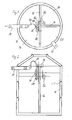
Fig. 1 zeigt einen Querschnitt durch eine sogenannte Dreikammergrube, die einen
zylindrischen Behälter 10 aufweist, der durch eine erste Trennwand 12 in
zwei gleiche Hälften unterteilt wird, von denen eine durch eine weitere Trennwand
14 noch einmal halbiert wird. Auf diese Weise entstehen eine Klärkammer
16 mit einem Umfangswinkel von 180° sowie zwei Vorklärkammern 18,20 mit
Umfangswinkeln von jeweils 90°, die miteinander verbunden sind und die Funktion
eines Schlammspeichers, Puffers und Absetzbeckens haben. Abwasser wird
durch einen Zulauf 22 in eines der Vorklärbecken 20 geleitet. Geklärtes Wasser
tritt durch einen Ablauf 24 aus der Klärkammer 16 aus.Fig. 1 shows a cross section through a so-called three-chamber pit, the one
has
Derartige Dreikammergruben wurden bereits bisher als Klärbecken benutzt, sind also bereits vorhanden und sollen durch die erfindungsgemäß vorgesehenen Aggregate nachgerüstet werden.Such three-chamber pits have previously been used as clarifiers, are therefore already present and are intended to be provided by those according to the invention Units can be retrofitted.
Damit dies in möglichst einfacher Weise möglich ist, kann beispielsweise ein
Rahmen oder eine Halterung 26 verwendet werden, an der die verschiedenen Aggregate
befestigt sind, so daß der gesamte Nachrüstsatz auf eine der Trennwände,
im dargestellten Beispiel die lange Trennwand 12 aufgehängt werden kann.
Natürlich ist es auch möglich, die Aggregate einzeln auf die Trennwände zu hängen
oder auf Schwimmkörpern zu montieren. Der Vollständigkeit halber sei erläutert,
daß bei dem dargestellten Beispiel auf der Halterung zum einen eine
Klarwasser-Entnahmepumpe 28 angebracht ist, die über einen Schlauch 30 mit
dem Ablauf 24 verbunden ist und geklärtes Wasser nach außen abgibt. Neben
der Klarwasser-Entnahmepumpe 28 befindet sich ein Belüfter 32, der über einen
von außen zugeführten, nur teilweise dargestellten Schlauch Außenluft aufnimmt
und in einem starken Pumpenstrahl abwärts in das Wasser der Klärkammer
drückt. Dadurch entstehen Luftblasen im Wasser, die nach oben aufsteigen
und bewirken, daß Sauerstoff in das Wasser eingetragen wird.So that this is possible in the simplest possible way, for example, a
Frame or a
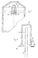
In der Vorklärkammer 18 befindet sich eine weitere Pumpe 36, die an ihrem
Ausgang mit einer Leitung 38 verbunden ist, die bogenförmig über die Trennwand
12 hinweg in die Klärkammer 16 geführt ist. Diese Pumpe 36 mit der Leitung
38 sind vergrößert in Fig. 4 dargestellt. Die Pumpe 36 dient dazu, das Abwasser,
das sich in den Vorklärkammern 18,20 gesammelt hat, über die Trennwand
12 hinweg in die Klärkammer 16 zu überführen. In the pre-clarification chamber 18 there is a
Dies kann durchaus in einem Maße geschehen, daß der Wasserspiegel in der
Klärkammer 16 erheblich höher liegt als der Wasserspiegel in der Vorklärkammer
18, wie etwa auch in Fig. 4 andeutungsweise gezeigt ist. Das ermöglicht
eine gute Nutzung des Volumens der Klärkammer 16. Wenn die Pumpe 36 bei
Verhältnissen abgeschaltet wird, wie sie in Fig. 4 angedeutet sind, und die Leitung
38 noch mit Wasser gefüllt ist, wird das Wasser aufgrund des Prinzips der
kommunizierenden Röhren aus der Klärkammer 16 zurück in die Vorklärkammer
18 fließen, und zwar umso rascher, je größer die Höhendifferenz zwischen
den beiden Wasserspiegeln ist.This can be done to such an extent that the water level in the
Auf der Seite der Klärkammer 16 befindet sich am unteren Ende der Leitung 38
eine nach unten offene Auffangschale 40. Durch den Belüfter 32 wird unterhalb
des Belüfters und damit auch unterhalb der Auffangschale 40 im Wasser ein
großer Bereich gebildet, in dem Luftblasen aufsteigen.On the side of the
Zumindest ein Teil dieser Luftblasen gelangt von unten in die Auffangschale und
bildet hier nach und nach ein Luftpolster, das durch die Leitung 38 aufsteigt
und im höchsten Bereich der Leitung 38 angesammelt wird. Wenn dieses Luftpolster
im oberen Bereich der Leitung 38 ein gewisses Volumen erreicht hat,
wird die Saugwirkung in Richtung der Vorklärkammer 18 unterbrochen. Es ist
daher beispielsweise möglich, mit Hilfe eines zu vorgegebener Zeit über eine vorgegebene
Länge abgegebenen Belüftungsstoßes in vorgegebenem Abstand zum
Ende des Betriebes der Pumpe 36 die Menge des zurücklaufenden Wasser-Schlamm-Gemisches
zu bestimmen. Nähere Einzelheiten können der Erprobung
durch den kundigen Fachmann überlassen bleiben.At least some of these air bubbles enter the drip tray and from below
here gradually forms an air cushion that rises through
In einer modifizierten Ausführungsform können die Klärkammer 16 und die vorklärkammer
18 auch durch getrennte Behälter gebildet werden. Die "Trennwand"
zwischen ihnen wird dann durch Teile der Wände der einzelnen Behälter
gebildet.In a modified embodiment, the
Claims (2)
Applications Claiming Priority (2)
| Application Number | Priority Date | Filing Date | Title |
|---|---|---|---|
| DE20116397U | 2001-10-05 | ||
| DE20116397U DE20116397U1 (en) | 2001-10-05 | 2001-10-05 | Waste water treatment device |
Publications (2)
| Publication Number | Publication Date |
|---|---|
| EP1300367A2 true EP1300367A2 (en) | 2003-04-09 |
| EP1300367A3 EP1300367A3 (en) | 2004-02-11 |
Family
ID=7962559
Family Applications (1)
| Application Number | Title | Priority Date | Filing Date |
|---|---|---|---|
| EP02022120A Withdrawn EP1300367A3 (en) | 2001-10-05 | 2002-10-02 | Small installation for the treatment of wastewater |
Country Status (3)
| Country | Link |
|---|---|
| EP (1) | EP1300367A3 (en) |
| DE (1) | DE20116397U1 (en) |
| HU (1) | HUP0203373A2 (en) |
Cited By (3)
| Publication number | Priority date | Publication date | Assignee | Title |
|---|---|---|---|---|
| EP1650169A1 (en) * | 2004-10-05 | 2006-04-26 | Markus Baumann | Biological clarification device with a submersible pump |
| DE202006015834U1 (en) * | 2006-10-16 | 2008-02-21 | Atb Umwelttechnologien Gmbh | suction device |
| EP2628712A1 (en) * | 2012-02-20 | 2013-08-21 | Sapling sp. z o. o. | Adiabatic, mechanical-biological sewage treatment plant |
Families Citing this family (1)
| Publication number | Priority date | Publication date | Assignee | Title |
|---|---|---|---|---|
| DE102020132301A1 (en) | 2020-12-04 | 2022-06-09 | Kordes Kld Wasser- Und Abwassersysteme Gmbh | waste water treatment plant |
Citations (4)
| Publication number | Priority date | Publication date | Assignee | Title |
|---|---|---|---|---|
| GB2317168A (en) * | 1996-09-12 | 1998-03-18 | Balmoral Group | Sequential batch reactor |
| DE19812397A1 (en) * | 1998-03-20 | 1999-09-23 | Oekoservice Ges Fuer Umweltana | Small-scale waste water biological treatment plant |
| DE20020795U1 (en) * | 1999-02-25 | 2001-03-01 | Baumann Markus | Waste water treatment device |
| DE20005909U1 (en) * | 2000-03-30 | 2001-08-09 | Boller Reinhard | Wastewater treatment plant |
-
2001
- 2001-10-05 DE DE20116397U patent/DE20116397U1/en not_active Expired - Lifetime
-
2002
- 2002-10-02 EP EP02022120A patent/EP1300367A3/en not_active Withdrawn
- 2002-10-04 HU HU0203373A patent/HUP0203373A2/en unknown
Patent Citations (4)
| Publication number | Priority date | Publication date | Assignee | Title |
|---|---|---|---|---|
| GB2317168A (en) * | 1996-09-12 | 1998-03-18 | Balmoral Group | Sequential batch reactor |
| DE19812397A1 (en) * | 1998-03-20 | 1999-09-23 | Oekoservice Ges Fuer Umweltana | Small-scale waste water biological treatment plant |
| DE20020795U1 (en) * | 1999-02-25 | 2001-03-01 | Baumann Markus | Waste water treatment device |
| DE20005909U1 (en) * | 2000-03-30 | 2001-08-09 | Boller Reinhard | Wastewater treatment plant |
Cited By (3)
| Publication number | Priority date | Publication date | Assignee | Title |
|---|---|---|---|---|
| EP1650169A1 (en) * | 2004-10-05 | 2006-04-26 | Markus Baumann | Biological clarification device with a submersible pump |
| DE202006015834U1 (en) * | 2006-10-16 | 2008-02-21 | Atb Umwelttechnologien Gmbh | suction device |
| EP2628712A1 (en) * | 2012-02-20 | 2013-08-21 | Sapling sp. z o. o. | Adiabatic, mechanical-biological sewage treatment plant |
Also Published As
| Publication number | Publication date |
|---|---|
| HUP0203373A2 (en) | 2003-07-28 |
| EP1300367A3 (en) | 2004-02-11 |
| HU0203373D0 (en) | 2002-12-28 |
| DE20116397U1 (en) | 2002-01-24 |
Similar Documents
| Publication | Publication Date | Title |
|---|---|---|
| EP2641876B1 (en) | Biological wastewater treatment device | |
| DE1642432B2 (en) | PURIFICATION AND FILTER SYSTEM | |
| DE102014015488B4 (en) | Bi-functional air lift for biological wastewater treatment plants, method of its operation and its use | |
| EP0732457B1 (en) | Process and device for reclaiming grey water | |
| DE2733044A1 (en) | IMPROVED WASTE WATER TREATMENT EQUIPMENT | |
| DE202008003062U1 (en) | Biological clarifier | |
| EP1031540B1 (en) | Apparatus for water treatment | |
| DE2357707B2 (en) | Equipment for the treatment or clarification of wastewater | |
| EP1650169B1 (en) | Biological clarification device with a submersible pump | |
| DE2231172A1 (en) | COMBINED DEVICE FOR BIOLOGICAL SEWAGE TREATMENT | |
| EP1300367A2 (en) | Small installation for the treatment of wastewater | |
| EP1559686B1 (en) | Clarification device with outlet device for clarified water | |
| EP2284128A2 (en) | Method and device for cleaning waste water and separation device for same | |
| DE102006005865A1 (en) | Pumping device for pumping wastewater | |
| DE19541940C2 (en) | Wastewater treatment plant for biological wastewater treatment | |
| EP3135636B1 (en) | Sewage system | |
| EP1110915A2 (en) | Device and method for biologically purifying waste water | |
| AT403373B (en) | BIOLOGICAL WASTEWATER PLANT AND METHOD FOR OPERATING SUCH A | |
| DE19816900C1 (en) | Tilting pipe with float controller and ball valve for discharging liquid | |
| DE3032036A1 (en) | Sewage treatment plant contg. well-type aeration basin - integrated with final settling tank for compact sewage treatment | |
| DE2510761A1 (en) | Purifying water carrying large amts of hydrocarbons - decelerating and cooling tank suitably partitioned yields relatively pure water | |
| EP1629881A1 (en) | Sewage treatment plant with membrane filtration | |
| WO1999057068A1 (en) | Fully biological premises sewage treatment installation | |
| EP3135637A1 (en) | Sbr waste water treatment plant | |
| DE2703402A1 (en) | Draw off line for heavy liquids in settler - having inverted funnel end with controlled run off below bulk liquid surface |
Legal Events
| Date | Code | Title | Description |
|---|---|---|---|
| PUAI | Public reference made under article 153(3) epc to a published international application that has entered the european phase |
Free format text: ORIGINAL CODE: 0009012 |
|
| AK | Designated contracting states |
Kind code of ref document: A2 Designated state(s): AT BE BG CH CY CZ DE DK EE ES FI FR GB GR IE IT LI LU MC NL PT SE SK TR Designated state(s): AT BE BG CH CY CZ DE DK EE ES FI FR GB GR IE IT LI LU MC NL PT SE SK TR |
|
| AX | Request for extension of the european patent |
Extension state: AL LT LV MK RO SI |
|
| PUAL | Search report despatched |
Free format text: ORIGINAL CODE: 0009013 |
|
| AK | Designated contracting states |
Kind code of ref document: A3 Designated state(s): AT BE BG CH CY CZ DE DK EE ES FI FR GB GR IE IT LI LU MC NL PT SE SK TR |
|
| AX | Request for extension of the european patent |
Extension state: AL LT LV MK RO SI |
|
| RIC1 | Information provided on ipc code assigned before grant |
Ipc: 7C 02F 3/00 B Ipc: 7C 02F 3/12 A |
|
| 17P | Request for examination filed |
Effective date: 20040108 |
|
| AKX | Designation fees paid |
Designated state(s): AT BE BG CH CY CZ DE DK EE ES FI FR GB GR IE IT LI LU MC NL PT SE SK TR |
|
| STAA | Information on the status of an ep patent application or granted ep patent |
Free format text: STATUS: THE APPLICATION IS DEEMED TO BE WITHDRAWN |
|
| 18D | Application deemed to be withdrawn |
Effective date: 20050503 |