EP1300199A1 - Schwingsieb - Google Patents
Schwingsieb Download PDFInfo
- Publication number
- EP1300199A1 EP1300199A1 EP02396147A EP02396147A EP1300199A1 EP 1300199 A1 EP1300199 A1 EP 1300199A1 EP 02396147 A EP02396147 A EP 02396147A EP 02396147 A EP02396147 A EP 02396147A EP 1300199 A1 EP1300199 A1 EP 1300199A1
- Authority
- EP
- European Patent Office
- Prior art keywords
- screen
- screen mesh
- mesh
- vibrating
- meshes
- Prior art date
- Legal status (The legal status is an assumption and is not a legal conclusion. Google has not performed a legal analysis and makes no representation as to the accuracy of the status listed.)
- Withdrawn
Links
Images

Classifications
-
- B—PERFORMING OPERATIONS; TRANSPORTING
- B07—SEPARATING SOLIDS FROM SOLIDS; SORTING
- B07B—SEPARATING SOLIDS FROM SOLIDS BY SIEVING, SCREENING, SIFTING OR BY USING GAS CURRENTS; SEPARATING BY OTHER DRY METHODS APPLICABLE TO BULK MATERIAL, e.g. LOOSE ARTICLES FIT TO BE HANDLED LIKE BULK MATERIAL
- B07B1/00—Sieving, screening, sifting, or sorting solid materials using networks, gratings, grids, or the like
- B07B1/18—Drum screens
- B07B1/22—Revolving drums
-
- B—PERFORMING OPERATIONS; TRANSPORTING
- B07—SEPARATING SOLIDS FROM SOLIDS; SORTING
- B07B—SEPARATING SOLIDS FROM SOLIDS BY SIEVING, SCREENING, SIFTING OR BY USING GAS CURRENTS; SEPARATING BY OTHER DRY METHODS APPLICABLE TO BULK MATERIAL, e.g. LOOSE ARTICLES FIT TO BE HANDLED LIKE BULK MATERIAL
- B07B1/00—Sieving, screening, sifting, or sorting solid materials using networks, gratings, grids, or the like
- B07B1/28—Moving screens not otherwise provided for, e.g. swinging, reciprocating, rocking, tilting or wobbling screens
-
- B—PERFORMING OPERATIONS; TRANSPORTING
- B07—SEPARATING SOLIDS FROM SOLIDS; SORTING
- B07B—SEPARATING SOLIDS FROM SOLIDS BY SIEVING, SCREENING, SIFTING OR BY USING GAS CURRENTS; SEPARATING BY OTHER DRY METHODS APPLICABLE TO BULK MATERIAL, e.g. LOOSE ARTICLES FIT TO BE HANDLED LIKE BULK MATERIAL
- B07B1/00—Sieving, screening, sifting, or sorting solid materials using networks, gratings, grids, or the like
- B07B1/46—Constructional details of screens in general; Cleaning or heating of screens
- B07B1/48—Stretching devices for screens
- B07B1/485—Devices for alternately stretching and sagging screening surfaces
-
- B—PERFORMING OPERATIONS; TRANSPORTING
- B07—SEPARATING SOLIDS FROM SOLIDS; SORTING
- B07B—SEPARATING SOLIDS FROM SOLIDS BY SIEVING, SCREENING, SIFTING OR BY USING GAS CURRENTS; SEPARATING BY OTHER DRY METHODS APPLICABLE TO BULK MATERIAL, e.g. LOOSE ARTICLES FIT TO BE HANDLED LIKE BULK MATERIAL
- B07B1/00—Sieving, screening, sifting, or sorting solid materials using networks, gratings, grids, or the like
- B07B1/46—Constructional details of screens in general; Cleaning or heating of screens
- B07B1/50—Cleaning
Definitions
- the invention relates to a vibrating screen comprising a screen frame intended to be reciprocatingly movable and a screen mesh attached thereto, onto which the material to be screened is supplied, whereby the material passing the screen mesh falls below it and the material not passing it flows along the inclined screen mesh and discharges out of its lower end.
- Vibrating screens comprise a substantially planar screen mesh, which is in known solutions tightly attached to the frame of the vibrating screen and mounted slightly inclined relative to the base.
- the material to be screened is supplied to the higher end of the screen mesh, and due to the vibration the finer material part falls through the screen mesh below it to be recovered, and correspondingly, coarser material not passing the holes of the screen mesh flows downwards along the screen mesh, discharging out of its lower end.
- the problem with vibrating screens is that part of such material that is not able to pass through the openings of the screen mesh is still able to fall so far into the opening that it does not move further downwards along the screen mesh but stays in the opening, clogging it. Clogging of the screen mesh, in turn, causes interruptions in operation, because the screen mesh must be cleaned in some way before the screening can be continued. Particularly when screening small materials having an elongated form, the cleaning of the screen mesh is difficult and may, in the worst case, even require that the screen mesh be detached or that the frame connected to it be turned upside down before the material stuck to the screen mesh can discharge.
- An object of the present invention is to provide a vibrating screen with which the interruptions and maintenance measures due to clogging of the screen can be essentially reduced or even completely eliminated.
- the vibrating screen according to the invention is characterized in that the vibrating screen comprising a screen frame intended to be reciprocatingly movable and a screen mesh attached thereto onto which the material to be screened is supplied, whereby the material passing the screen mesh falls below it and the material not passing it flows along the inclined screen mesh and discharges out of its lower end.
- the essential idea of the invention is that two or more, preferably four, screen meshes are used in the vibrating screen, the screen meshes being mounted angularly relative to each other, preferably in such a way that they form a rectangular channel.
- the vibrating screen according to the invention is characterized in that the screen meshes are attached to the frame of the vibrating screen only by two opposite edges in such a way that the sides between these edges can move relative to the screen frame.
- the vibrating screen according to the invention is characterized in that each screen mesh is, in turn, turnable into the screening position, and correspondingly out of the position.
- the vibrating screen according to the invention is characterized in that it comprises separate tightening means connected to the screen meshes in such a way that the screen mesh turned into the screening position is tight in the screening position, enabling screening, but when being turned out of the screening position, it can be let loose, whereby the material that has stayed in the meshes, i.e. openings, of the screen mesh can easily discharge from the screen mesh, aided by the vibrating screen.
- the detachment of the material is particularly efficient when the screen mesh has turned completely upside down relative to the screening position, so that the material stuck to the holes can directly fall downwards onto the screen mesh below it and thus discharge out of the vibrating screen.
- Figure 1 shows a schematic side view of a vibrating screen according to the invention
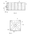
- Figure 2 shows a schematic view of a vibrating screen according to the invention, sectioned in the cross-direction thereof;
- Figure 3 shows a schematic longitudinal section view of a vibrating screen according to the invention.
- a vibrating screen schematically shown in Figure 1, comprising a screen frame 2, to which screen meshes 3 are attached.
- the screen mesh 2 is connected to an axle 4 in such a way that it is rotational about the axle.
- the axle 4 in turn, is rotationally fitted with a bearing against supports 5a and 5b.
- a turning motor 6 is connected to the axle 4 and the support 5b to turn the screen frame 2 and the screen meshes 3 on it about the axle 4.
- the supports 5a and 5b are connected to a support frame 7, to which, in turn, a vibrating motor 8 is connected.
- the support frame 7 is connected by its ends or close to its ends to springs 9 against support parts 10 of a separate base not illustrated, in such a way that the screen frame and the screen meshes are inclined relative to the horizontal plane, i.e. the base.
- the material to be screened is supplied onto the lowest screen mesh not illustrated in the figure, in the way indicated by arrow A, whereby the material passing the screen mesh falls through the opening in the support frame 7, in the way indicated by arrows B, to be recovered for instance to a suitable platform or other base, and the material not passing the screen mesh discharges in the way indicated by arrow C out of the other end of the screen frame 2 through a possibly used guiding plate 11 to a place different from the one where the material which has passed through the screen mesh discharges.
- the vibrating motor 8 is an eccentric vibrator, which, when rotating, causes the whole vibrating screen supported by the springs 9 to vibrate reciprocatingly. Due to the effect of this reciprocating motion and gravity, the material supplied to the screen mesh flows gradually along the screen mesh towards its lower end, whereby the material passing the screen mesh falls on its way through the screen mesh, while the material not passing the screen mesh travels along the screen mesh until it falls out of the lower end of the vibrating screen when the screen mesh ends.
- vibrating screen operation and vibrating motor operation like this are generally fully known and obvious to a person skilled in the art, so that there is no reason to explain them in more detail.
- Figure 2 shows a schematic cross-section of an embodiment of the vibrating screen according to the invention in the longitudinal direction thereof. To clarify the structure, the screen mesh parts and screen frame parts on the sides have been omitted from the figure.
- the screen frame 2 comprises cross-direction supports positioned on the opposite side of the screen mesh 3. These supports are positioned, relative to the screen mesh 3, on the other side than to which the material to be screened is supplied. In this way, the screen mesh gets support from below, as there is material to be screened upon it, pressing it downwards.
- the screen mesh 3 is attached to the screen frame 2 by its right edge, and correspondingly, to a tightening beam 12 by its left edge.
- the tightening beam 12 in turn, can move in the longitudinal direction of the screen frame 2, in other words in the horizontal direction of the figure in such a way that the screen mesh can be tightened with it.
- the screen mesh is not attached to anything by its upper or lower edges, but can move freely relative to the screen frame 2.
- the tightening beam 12 in turn, is attached to an anchor tie beam 14 with pre-tightening bolts 13.
- Nuts 16 in the pre-tightening bolts 13 allow the pre-tightening of the screen mesh to be adjusted as desired, the actual tightening during the screening being performed with the tightening cylinder 15.
- the figure shows a support plate 17, by means of which the tightening cylinder 15 is connected to the screen frame 2.
- Figure 3 shows a cross-section of the screen frame of the vibrating cylinder and of the screen meshes mounted on it.
- the screen frame 2 has in this embodiment a rectangular section and there are screen meshes 3 mounted on each side of it.
- the figure shows a turning axle 4 and a support grid 18 between the screen frame and the turning axle 4.
- the figure shows schematically an embodiment for supporting the edges of the screen meshes 3 against the screen frame. This has been done by using, for instance, Y-shaped support profiles 19 shown in the figure, which profiles extend in the direction of the loose sides of the screen meshes 3 over the length of their sides.
- the screen frame comprises grooves for the loose edges of the screen meshes, in which grooves the edges of the screen meshes 3 can be positioned in such a way that the material to be screened is prevented from travelling past the edges of the screen meshes.
- the lowest screen mesh 3 must be tight in order to allow screening. This is done by tightening it by means of the tightening cylinder 15 shown in Figure 2. At the same time, the rest of the screen meshes can be as loose as is possible, taking the normal pre-tightening into account, whereby the material possibly stuck to their openings can fall more easily out of them, and in this way the screen meshes 3 remain clean.
- the screen mesh is turned away by turning the screen frame 90°, whereby correspondingly another screen mesh 3, having remained on the side, is turned into the screening position.
- the screen mesh In order not to interrupt or disturb the screening in any way it is preferable to tighten the screen mesh to be turned into the screening position tight as early as before turning it into the screening position, so that the screening can be continued also during the turning motion.
- the screening mesh previously in the screening position is released from tightening by means of the tightening cylinder 15, whereby the material stuck to it can fall out.
- the vibrating screen according to the invention that rather a short time of screening can be performed with one screen mesh at a time, whereby the material particles having stopped in the holes have no time to be stuck to the holes but remain loose and thus easily detach from the holes of the screen mesh when the screen mesh is turned upright and, correspondingly, upside down.
- this rotational motion is implemented in such a way that the screen frame 2 and the screen meshes 3 are turned by means of the turning motor 6 with steps of 90°, in total at most 360°, whereby it is possible to use a fixed pressure medium hose system for the use of the tightening cylinders 15 without a need for separate sealed lead-through structures of pressure medium channels.
- the screen frame and the screen meshes are turned the same amount by means of the turning motor 6 in the opposite direction, again with steps of 90°, whereby the vibrating screen still operates by means of reciprocating turning motions.
- the vibrating screen also comprises a separate control apparatus not shown, having a control member for controlling the turning motor 6 into the next screening position after a predetermined time, according to what has been described above.
- the control apparatus preferably comprises control means for controlling the tightening cylinders of the screen meshes in such a way that each screen mesh is, as required, tightened into the screening tightness and correspondingly released from it when it is not in the screening position.
- the screen frame has a substantially rectangular cross-section, and four screen meshes that form a substantially rectangular channel inside them.
- a structure including only two or three screen meshes whereby the manufacturing costs would naturally be lower but the number of screen meshes would correspondingly be smaller.
- a structure with five or six screen meshes for instance.
Applications Claiming Priority (2)
| Application Number | Priority Date | Filing Date | Title |
|---|---|---|---|
| FI20011927 | 2001-10-02 | ||
| FI20011927A FI20011927A (fi) | 2001-10-02 | 2001-10-02 | Täryseula |
Publications (1)
| Publication Number | Publication Date |
|---|---|
| EP1300199A1 true EP1300199A1 (de) | 2003-04-09 |
Family
ID=8561988
Family Applications (1)
| Application Number | Title | Priority Date | Filing Date |
|---|---|---|---|
| EP02396147A Withdrawn EP1300199A1 (de) | 2001-10-02 | 2002-09-26 | Schwingsieb |
Country Status (2)
| Country | Link |
|---|---|
| EP (1) | EP1300199A1 (de) |
| FI (1) | FI20011927A (de) |
Cited By (12)
| Publication number | Priority date | Publication date | Assignee | Title |
|---|---|---|---|---|
| CN102318882A (zh) * | 2011-07-18 | 2012-01-18 | 舒城圣桂食品有限公司 | 往复震动型水煮薇菜自动去杂机 |
| CN102825006A (zh) * | 2012-07-25 | 2012-12-19 | 江苏永钢集团有限公司 | 一种振动筛防尘罩 |
| CN102825001A (zh) * | 2012-09-14 | 2012-12-19 | 中冶南方工程技术有限公司 | 一种粉状物料滚筒筛 |
| CN103286064A (zh) * | 2013-05-08 | 2013-09-11 | 辽宁东戴河新区和陆重科有限公司 | 一种数控电磁驱动振动除尘分级筛 |
| CN103406258A (zh) * | 2013-09-02 | 2013-11-27 | 长沙矿冶研究院有限责任公司 | 一种高频振动筛 |
| CN104568486A (zh) * | 2014-12-31 | 2015-04-29 | 埃里斯克矿山工程机械有限公司 | 筛分机测试平台 |
| CN104941910A (zh) * | 2015-06-23 | 2015-09-30 | 龙建春 | 多层茶叶抖筛机 |
| CN107413617A (zh) * | 2017-04-27 | 2017-12-01 | 昆明理工大学 | 一种筛网震动式甘蔗渣除髓机 |
| CN108745852A (zh) * | 2018-06-06 | 2018-11-06 | 仙居县顺安交通设施有限公司 | 自动筛分设备 |
| CN113560165A (zh) * | 2021-05-17 | 2021-10-29 | 重庆取予科技有限公司 | 一种固体团状物筛分机 |
| CN113857027A (zh) * | 2021-10-13 | 2021-12-31 | 双牌县丰泰农机设备有限公司 | 一种粮食筛选机 |
| CN117399262A (zh) * | 2023-12-13 | 2024-01-16 | 山东江拓机械设备有限公司 | 一种石英制品生产加工用石英石筛选设备 |
Families Citing this family (1)
| Publication number | Priority date | Publication date | Assignee | Title |
|---|---|---|---|---|
| CN106733632A (zh) * | 2016-12-16 | 2017-05-31 | 芜湖航达网业有限公司 | 一种矿石用过滤网 |
Citations (5)
| Publication number | Priority date | Publication date | Assignee | Title |
|---|---|---|---|---|
| DE1186729B (de) * | 1964-05-09 | 1965-02-04 | Christian Huelsmeyer | Drehbares Vibrationssieb mit zwei oder mehreren Siebflaechen |
| DE2015845A1 (en) * | 1970-04-02 | 1971-10-14 | Dorst Keramikmaschinenbau, Inh Otto Dorst u Dipl Ing Walter Schlegel, 8113Kochel | Vibratory sieve for use with dense tacky substances |
| EP0158036A1 (de) * | 1984-03-31 | 1985-10-16 | Hein, Lehmann Aktiengesellschaft | Trommelsiebmaschine |
| EP0184006A1 (de) * | 1984-11-06 | 1986-06-11 | Mogensen GmbH & Co KG | Verfahren und Vorrichtung zum Reinigen der Siebböden insbes. bei Vibrationsklassiermaschinen der Mehrdeckausführung |
| US4702826A (en) * | 1986-02-03 | 1987-10-27 | Rotex, Inc. | Screen cleaner for particle size analyzer |
-
2001
- 2001-10-02 FI FI20011927A patent/FI20011927A/fi unknown
-
2002
- 2002-09-26 EP EP02396147A patent/EP1300199A1/de not_active Withdrawn
Patent Citations (5)
| Publication number | Priority date | Publication date | Assignee | Title |
|---|---|---|---|---|
| DE1186729B (de) * | 1964-05-09 | 1965-02-04 | Christian Huelsmeyer | Drehbares Vibrationssieb mit zwei oder mehreren Siebflaechen |
| DE2015845A1 (en) * | 1970-04-02 | 1971-10-14 | Dorst Keramikmaschinenbau, Inh Otto Dorst u Dipl Ing Walter Schlegel, 8113Kochel | Vibratory sieve for use with dense tacky substances |
| EP0158036A1 (de) * | 1984-03-31 | 1985-10-16 | Hein, Lehmann Aktiengesellschaft | Trommelsiebmaschine |
| EP0184006A1 (de) * | 1984-11-06 | 1986-06-11 | Mogensen GmbH & Co KG | Verfahren und Vorrichtung zum Reinigen der Siebböden insbes. bei Vibrationsklassiermaschinen der Mehrdeckausführung |
| US4702826A (en) * | 1986-02-03 | 1987-10-27 | Rotex, Inc. | Screen cleaner for particle size analyzer |
Cited By (18)
| Publication number | Priority date | Publication date | Assignee | Title |
|---|---|---|---|---|
| CN102318882B (zh) * | 2011-07-18 | 2013-07-31 | 舒城圣桂食品有限公司 | 往复震动型水煮薇菜自动去杂机 |
| CN102318882A (zh) * | 2011-07-18 | 2012-01-18 | 舒城圣桂食品有限公司 | 往复震动型水煮薇菜自动去杂机 |
| CN102825006A (zh) * | 2012-07-25 | 2012-12-19 | 江苏永钢集团有限公司 | 一种振动筛防尘罩 |
| CN102825001A (zh) * | 2012-09-14 | 2012-12-19 | 中冶南方工程技术有限公司 | 一种粉状物料滚筒筛 |
| CN102825001B (zh) * | 2012-09-14 | 2015-05-20 | 中冶南方工程技术有限公司 | 一种粉状物料滚筒筛 |
| CN103286064A (zh) * | 2013-05-08 | 2013-09-11 | 辽宁东戴河新区和陆重科有限公司 | 一种数控电磁驱动振动除尘分级筛 |
| CN103286064B (zh) * | 2013-05-08 | 2016-04-20 | 辽宁东戴河新区和陆重科有限公司 | 一种数控电磁驱动振动除尘分级筛 |
| CN103406258B (zh) * | 2013-09-02 | 2016-06-15 | 长沙矿冶研究院有限责任公司 | 一种高频振动筛 |
| CN103406258A (zh) * | 2013-09-02 | 2013-11-27 | 长沙矿冶研究院有限责任公司 | 一种高频振动筛 |
| CN104568486A (zh) * | 2014-12-31 | 2015-04-29 | 埃里斯克矿山工程机械有限公司 | 筛分机测试平台 |
| CN104941910A (zh) * | 2015-06-23 | 2015-09-30 | 龙建春 | 多层茶叶抖筛机 |
| CN107413617A (zh) * | 2017-04-27 | 2017-12-01 | 昆明理工大学 | 一种筛网震动式甘蔗渣除髓机 |
| CN107413617B (zh) * | 2017-04-27 | 2022-12-23 | 昆明理工大学 | 一种筛网震动式甘蔗渣除髓机 |
| CN108745852A (zh) * | 2018-06-06 | 2018-11-06 | 仙居县顺安交通设施有限公司 | 自动筛分设备 |
| CN113560165A (zh) * | 2021-05-17 | 2021-10-29 | 重庆取予科技有限公司 | 一种固体团状物筛分机 |
| CN113857027A (zh) * | 2021-10-13 | 2021-12-31 | 双牌县丰泰农机设备有限公司 | 一种粮食筛选机 |
| CN117399262A (zh) * | 2023-12-13 | 2024-01-16 | 山东江拓机械设备有限公司 | 一种石英制品生产加工用石英石筛选设备 |
| CN117399262B (zh) * | 2023-12-13 | 2024-03-22 | 禄晨新材料技术研发(山东)有限公司 | 一种石英制品生产加工用石英石筛选设备 |
Also Published As
| Publication number | Publication date |
|---|---|
| FI20011927A0 (fi) | 2001-10-02 |
| FI20011927A (fi) | 2003-04-03 |
Similar Documents
| Publication | Publication Date | Title |
|---|---|---|
| US6575304B2 (en) | Vibrating screen apparatus | |
| EP1300199A1 (de) | Schwingsieb | |
| EP3525940B1 (de) | Vibrations-siebmaschine | |
| US5816413A (en) | Wire screen deck having replaceable modular screen panels | |
| US4911834A (en) | Drilling mud separation system | |
| US7922003B2 (en) | Magnetic screen clamping | |
| US6155428A (en) | Vibratory screening machine | |
| US20090206011A1 (en) | Vibrating Screen Apparatus | |
| US5816412A (en) | Screening systems and methods for screening particulate material | |
| US20100018910A1 (en) | Screening machine screen panel | |
| NO342702B1 (en) | Dual screen assembly for vibrating screening machine | |
| US4505812A (en) | Sieve screen deck | |
| US5336408A (en) | Apparatus for separating particles from a fluid stream | |
| US6679386B2 (en) | Low-density particle sizing apparatus and method | |
| US8631945B1 (en) | Method for screening fine industrial minerals using a vibrating high speed screening unit | |
| CN116442432B (zh) | 一种再生塑料颗粒上料输送装置 | |
| US5397002A (en) | Variable control screen apparatus | |
| US3655045A (en) | Method and apparatus for conveying and separating materials | |
| CN210282868U (zh) | 用于筛分塑料颗粒的振动筛 | |
| CA1275975C (en) | Method and apparatus for cleaning of screen-cloths in particular at vibrating screening equipment | |
| EP1013348B1 (de) | Sieblose vibrationstrennvorrichtung | |
| JP2670988B2 (ja) | 付着性原料用篩分機付払出し装置及び付着性原料篩分払出し方法 | |
| CN213032991U (zh) | 一种振筛机 | |
| JP2012076054A (ja) | 振動スクリーン | |
| JP2729589B2 (ja) | 篩分機付払出し装置 |
Legal Events
| Date | Code | Title | Description |
|---|---|---|---|
| PUAI | Public reference made under article 153(3) epc to a published international application that has entered the european phase |
Free format text: ORIGINAL CODE: 0009012 |
|
| AK | Designated contracting states |
Kind code of ref document: A1 Designated state(s): AT BE BG CH CY CZ DE DK EE ES FI FR GB GR IE IT LI LU MC NL PT SE SK TR Designated state(s): AT BE BG CH CY CZ DE DK EE ES FI FR GB GR IE IT LI LU MC NL PT SE SK TR |
|
| AX | Request for extension of the european patent |
Extension state: AL LT LV MK RO SI |
|
| 17P | Request for examination filed |
Effective date: 20030714 |
|
| AKX | Designation fees paid |
Designated state(s): AT BE BG CH CY CZ DE DK EE ES FI FR GB GR IE IT LI LU MC NL PT SE SK TR |
|
| GRAP | Despatch of communication of intention to grant a patent |
Free format text: ORIGINAL CODE: EPIDOSNIGR1 |
|
| STAA | Information on the status of an ep patent application or granted ep patent |
Free format text: STATUS: THE APPLICATION IS DEEMED TO BE WITHDRAWN |
|
| 18D | Application deemed to be withdrawn |
Effective date: 20061115 |