EP1297737A1 - Déchiqueteur - Google Patents
Déchiqueteur Download PDFInfo
- Publication number
- EP1297737A1 EP1297737A1 EP02021581A EP02021581A EP1297737A1 EP 1297737 A1 EP1297737 A1 EP 1297737A1 EP 02021581 A EP02021581 A EP 02021581A EP 02021581 A EP02021581 A EP 02021581A EP 1297737 A1 EP1297737 A1 EP 1297737A1
- Authority
- EP
- European Patent Office
- Prior art keywords
- mean
- knives
- cylinder
- blade
- rolling
- Prior art date
- Legal status (The legal status is an assumption and is not a legal conclusion. Google has not performed a legal analysis and makes no representation as to the accuracy of the status listed.)
- Withdrawn
Links
Images


Classifications
-
- A—HUMAN NECESSITIES
- A01—AGRICULTURE; FORESTRY; ANIMAL HUSBANDRY; HUNTING; TRAPPING; FISHING
- A01D—HARVESTING; MOWING
- A01D34/00—Mowers; Mowing apparatus of harvesters
- A01D34/01—Mowers; Mowing apparatus of harvesters characterised by features relating to the type of cutting apparatus
- A01D34/412—Mowers; Mowing apparatus of harvesters characterised by features relating to the type of cutting apparatus having rotating cutters
- A01D34/42—Mowers; Mowing apparatus of harvesters characterised by features relating to the type of cutting apparatus having rotating cutters having cutters rotating about a horizontal axis, e.g. cutting-cylinders
- A01D34/52—Cutting apparatus
- A01D34/535—Cutting apparatus with cutting members pivotally attached to the rotating axle, e.g. flails
-
- A—HUMAN NECESSITIES
- A01—AGRICULTURE; FORESTRY; ANIMAL HUSBANDRY; HUNTING; TRAPPING; FISHING
- A01B—SOIL WORKING IN AGRICULTURE OR FORESTRY; PARTS, DETAILS, OR ACCESSORIES OF AGRICULTURAL MACHINES OR IMPLEMENTS, IN GENERAL
- A01B33/00—Tilling implements with rotary driven tools, e.g. in combination with fertiliser distributors or seeders, with grubbing chains, with sloping axles, with driven discs
- A01B33/08—Tools; Details, e.g. adaptations of transmissions or gearings
- A01B33/10—Structural or functional features of the tools ; Theoretical aspects of the cutting action
- A01B33/103—Structural or functional features of the tools ; Theoretical aspects of the cutting action the rotating shaft being oriented horizontally
-
- A—HUMAN NECESSITIES
- A01—AGRICULTURE; FORESTRY; ANIMAL HUSBANDRY; HUNTING; TRAPPING; FISHING
- A01G—HORTICULTURE; CULTIVATION OF VEGETABLES, FLOWERS, RICE, FRUIT, VINES, HOPS OR SEAWEED; FORESTRY; WATERING
- A01G23/00—Forestry
- A01G23/02—Transplanting, uprooting, felling or delimbing trees
- A01G23/06—Uprooting or pulling up trees; Extracting or eliminating stumps
- A01G23/067—Uprooting or pulling up trees; Extracting or eliminating stumps by comminuting the tree stumps
Definitions
- the present invention relates the agricultural devices, particularly the invention refers to a shredder device fit for agricultural means or for road maintenance and the like to shred, on the field, saplings, branches and bushes.
- shredder device consisting in a shaft or drum having a plurality of couples of divergent knives for the shred bushes, saplings and branches; the shaft is rotated by a motor and, generally, is moved by an arm installed on a vehicle.
- the main drawback of the known shredder device consists in that the blades of the coupled knives, being reciprocally distant, shear the stems and the branches in pieces of excessive dimension, making dangerous to walk on the ground, on which said pieces are spread, making too long the necessary time for their biological degradation and making difficult and expensive theirs possible harvest and disposal.
- the main object of the present invention is to propose a device shredder fit to shred branches, stems, bushes and similar in small pieces which are not an obstacle and which require short times of biodegradation and which have a reduced volume for an easy collect and disposal.
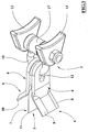
- numeral 1 indicates the device object of the present invention provided with a cylinder 2 having a plurality of connection means 3, whose each one rotatably supports two divergent knives 4, between which a straight knife 5 is interposed.
- the divergent 4 and straight 5 knives are made of steel and with rectangular cross section and have, in correspondence of one of their ends, a buttonhole hole 12 for joining the respective connection mean 3 and, in correspondence of the other end, respective blade portions first 6 and second 7.
- the first blade portions 6 of the divergent knives 4 of each connection mean 3 carries out with the related and adjacent second blade portion 7, an angle included between 30° and 60°, preferably 45°.
- the blade portions first 6 and second 7 have, carried out on opposed sides of a same face, respective cutting planes first 8 and second 9 joined at the opposed face by respective first leading edges 10 and second leading edges 11.
- the second cutting planes 9 and second leading edges 11 of the straight knives 5, have respectively a longitudinal extension, namely a length, greater and a thickness smaller with respect to the first cutting planes 8 and the first leading edges 10 of the divergent knives 4.
- the first cutting planes 8 are carried out in correspondence of the face of the corresponding first blade 6 opposed to the respective first knife 5.
- Each connection mean 3 includes at least two flanges 13 rigidly fixed by welding to the cylinder 2, and rotatably connected to the related knives 4, 5 through a "U" shaped member 15 engaged with the coupling holes 12 of the related knives 4, 5 and whose ends have respective opposed buttonholes 16 rotatably engaged in a pin 14 parallel to the cylinder 2 and fixed to the flanges 13.
- the dimensions of the coupling holes 12 are such to allows to the knives 4, 5 independent and articulated motions of moderate translation and rotations with respect to the shaped member 15.
- the pin 14 also supports a sleeve 17 interposed between the buttonholes 16 and fit for strengthening the related connection mean 3.
- the end portions of the cylinder 2 have respectively a first disk 18 and a second disk 19 each one having peripherally a plurality of fixing means 20, consisting in corresponding fixing holes 21, eventually threaded, and fit for removably fixing balancing masses.
- the second disk 19 has a plurality of fixing openings 22 for coupling a motor mean 23, of hydraulic type, fixed to a protection carter 26.
- the end of the cylinder 2 corresponding to the first disk 18 has an axial support 24, with cylindrical pivot shape, coupled to a rolling mean 27 through a bush mean 28 made of casehardened steel and removably fixed to the rolling mean 27 and to the axial support 24.
- the bush mean 28 has a surface contacting the axial support 24 larger than the inner cylindrical surface of the rolling mean 27, preferably the double.
- the rolling mean 27 consisting of a roller bearing, is removably housed in a tubular cylindrical seat 25 bolted to the protection carter 26.
- the rolling mean 27 is retained in seat by blocking means 30, consisting of a disc shaped element, locked by an elastic ring engaged in a throat groove carried out in correspondence of the free end of the seat 25.
- the blocking means 30 are provided with gasket means 31 for the hydraulic seal between the disc shaped element and the seat 25, whose remaining end has revolving seal means 29, consisting of an oil retainer, mating the bush 28. Therefore, the rolling mean is housed in a watertight cavity, which can be filled with lubricant through a lubricator.
- connection means 3 are preferably positioned along a spiral of the axial support 2 for better offsetting the knives.
- the operation of the device 1 provides that in an activation condition of the motor mean 23, the rotation of the cylinder 2, up to over 3000 revolutions per minute, causes for centrifugal effect, the radial alignment of the knives 4, 5 which, following the carter 26 movement, impact branches, stems and similar.
- the leading edge 11, the length and the thickness of the cutting plane 9, make the second blade portions 7 sharper and more penetrating than the first blade portions 6 and consequently the straight knife 5 stand out during the cutting the two divergent knives 4, in such a way that the branch portion interposed between these last ones is cut in two parts by the straight knife 5.
- the protection carter 26 avoids that the fragments and the cut portions can be dangerously threw towards people or things.
- the fixing means 20 allow performing the electronic balancing of the device 1, advantageously guaranteeing the reduction and the suppression of the vibrations and noise in all the operational conditions of the device 1.
- the main advantage of the present invention is to provide a shredder device fit to shred branches, stems, bushes and similar in small pieces which are not an obstacle and which require short biodegradation times and have a reduced volume for an easy harvest and disposal.
- Further advantage of the present invention is to provide a device, which is easy to be manufactured, cheap, and high reliable.
Landscapes
- Life Sciences & Earth Sciences (AREA)
- Environmental Sciences (AREA)
- Biodiversity & Conservation Biology (AREA)
- Ecology (AREA)
- Forests & Forestry (AREA)
- Engineering & Computer Science (AREA)
- Mechanical Engineering (AREA)
- Soil Sciences (AREA)
- Crushing And Pulverization Processes (AREA)
- Disintegrating Or Milling (AREA)
Applications Claiming Priority (2)
| Application Number | Priority Date | Filing Date | Title |
|---|---|---|---|
| ITBO20010596 | 2001-09-27 | ||
| ITBO20010596 ITBO20010596A1 (it) | 2001-09-27 | 2001-09-27 | Dispositivo trinciatore |
Publications (1)
| Publication Number | Publication Date |
|---|---|
| EP1297737A1 true EP1297737A1 (fr) | 2003-04-02 |
Family
ID=11439641
Family Applications (1)
| Application Number | Title | Priority Date | Filing Date |
|---|---|---|---|
| EP02021581A Withdrawn EP1297737A1 (fr) | 2001-09-27 | 2002-09-26 | Déchiqueteur |
Country Status (2)
| Country | Link |
|---|---|
| EP (1) | EP1297737A1 (fr) |
| IT (1) | ITBO20010596A1 (fr) |
Cited By (11)
| Publication number | Priority date | Publication date | Assignee | Title |
|---|---|---|---|---|
| EP1481581A1 (fr) * | 2003-05-28 | 2004-12-01 | Noremat | Dispositif de fixation de fléau pour appareil de broyage ou de fauche |
| EP1570718A1 (fr) * | 2004-03-06 | 2005-09-07 | Spearhead Machinery Ltd. | Faucheuse à fléaux |
| DE102004019213A1 (de) * | 2004-04-21 | 2005-11-17 | Maschinenfabrik Bermatingen Gmbh & Co | Ballenpresse |
| FR2881916A1 (fr) * | 2005-02-08 | 2006-08-18 | Suire Soc Par Actions Simplifi | Broyeur a axe horizontal ayant une bonne uniformite de broyage |
| EP1849347A1 (fr) * | 2006-04-28 | 2007-10-31 | Kuhn-Audureau S.A. | Rotor équilibré pour épareuse et procédé d'équilibrage d'un tel rotor |
| EP1869963A2 (fr) * | 2006-06-21 | 2007-12-26 | Nobili S.p.A. | Appareil pour déchiqueter un matériau |
| FR2955733A1 (fr) * | 2010-02-03 | 2011-08-05 | Thierry Bergeault | Dispositif d'assemblage/desassemblage d'elements amovibles sur un rotor de machine |
| EP2366275A1 (fr) | 2010-03-16 | 2011-09-21 | Kuhn-Audureau S.A. | Dispositif de fixation de couteaux sur le rotor d'une faucheuse-débroussailleuse |
| DE102016007458A1 (de) * | 2016-06-21 | 2018-02-15 | Gerhard Dücker GmbH & Co. KG Landmaschinenfabrik | Mäh- und/oder Schneidgerät |
| JP2019106972A (ja) * | 2017-12-20 | 2019-07-04 | 松山株式会社 | 農作業機およびそのカバー |
| JP2020078249A (ja) * | 2018-11-12 | 2020-05-28 | ウソン プレシジョン インダストリアル カンパニー,リミテッド | ショベルマウントロータリー式除草機{Excavator−mounted rotary mowers} |
Citations (5)
| Publication number | Priority date | Publication date | Assignee | Title |
|---|---|---|---|---|
| DE1100369B (de) * | 1960-04-02 | 1961-02-23 | Int Harvester Co | Schlegelwerk fuer Schlegelmaehhaecksler |
| GB895159A (en) * | 1960-04-20 | 1962-05-02 | Mott Corp | Blade connection for mowers |
| FR1468662A (fr) * | 1964-10-02 | 1967-02-10 | Mott Corp | Structure de lames pour faucheuses |
| GB1223042A (en) * | 1968-05-16 | 1971-02-17 | Int Harvester Co | Flail knife assembly |
| DE8704846U1 (fr) * | 1986-04-05 | 1987-06-25 | Amazonen-Werke H. Dreyer Gmbh & Co Kg, 4507 Hasbergen, De |
-
2001
- 2001-09-27 IT ITBO20010596 patent/ITBO20010596A1/it unknown
-
2002
- 2002-09-26 EP EP02021581A patent/EP1297737A1/fr not_active Withdrawn
Patent Citations (5)
| Publication number | Priority date | Publication date | Assignee | Title |
|---|---|---|---|---|
| DE1100369B (de) * | 1960-04-02 | 1961-02-23 | Int Harvester Co | Schlegelwerk fuer Schlegelmaehhaecksler |
| GB895159A (en) * | 1960-04-20 | 1962-05-02 | Mott Corp | Blade connection for mowers |
| FR1468662A (fr) * | 1964-10-02 | 1967-02-10 | Mott Corp | Structure de lames pour faucheuses |
| GB1223042A (en) * | 1968-05-16 | 1971-02-17 | Int Harvester Co | Flail knife assembly |
| DE8704846U1 (fr) * | 1986-04-05 | 1987-06-25 | Amazonen-Werke H. Dreyer Gmbh & Co Kg, 4507 Hasbergen, De |
Cited By (15)
| Publication number | Priority date | Publication date | Assignee | Title |
|---|---|---|---|---|
| EP1481581A1 (fr) * | 2003-05-28 | 2004-12-01 | Noremat | Dispositif de fixation de fléau pour appareil de broyage ou de fauche |
| FR2855365A1 (fr) * | 2003-05-28 | 2004-12-03 | Noremat | Dispositif de fixation de fleau pour appareil de broyage ou de fauche |
| EP1570718A1 (fr) * | 2004-03-06 | 2005-09-07 | Spearhead Machinery Ltd. | Faucheuse à fléaux |
| DE102004019213A1 (de) * | 2004-04-21 | 2005-11-17 | Maschinenfabrik Bermatingen Gmbh & Co | Ballenpresse |
| FR2881916A1 (fr) * | 2005-02-08 | 2006-08-18 | Suire Soc Par Actions Simplifi | Broyeur a axe horizontal ayant une bonne uniformite de broyage |
| EP1849347A1 (fr) * | 2006-04-28 | 2007-10-31 | Kuhn-Audureau S.A. | Rotor équilibré pour épareuse et procédé d'équilibrage d'un tel rotor |
| FR2900309A1 (fr) * | 2006-04-28 | 2007-11-02 | Kuhn Audureau Sa Sa | Rotor equilibre pour epareuse et procede d'equilibrage d'un tel rotor |
| EP1869963A2 (fr) * | 2006-06-21 | 2007-12-26 | Nobili S.p.A. | Appareil pour déchiqueter un matériau |
| EP1869963A3 (fr) * | 2006-06-21 | 2008-03-26 | Nobili S.p.A. | Appareil pour déchiqueter un matériau |
| FR2955733A1 (fr) * | 2010-02-03 | 2011-08-05 | Thierry Bergeault | Dispositif d'assemblage/desassemblage d'elements amovibles sur un rotor de machine |
| EP2366275A1 (fr) | 2010-03-16 | 2011-09-21 | Kuhn-Audureau S.A. | Dispositif de fixation de couteaux sur le rotor d'une faucheuse-débroussailleuse |
| FR2957482A1 (fr) * | 2010-03-16 | 2011-09-23 | Kuhn Audureau Sa | Dispositif de fixation de couteaux sur le rotor d'une faucheuse-debroussailleuse |
| DE102016007458A1 (de) * | 2016-06-21 | 2018-02-15 | Gerhard Dücker GmbH & Co. KG Landmaschinenfabrik | Mäh- und/oder Schneidgerät |
| JP2019106972A (ja) * | 2017-12-20 | 2019-07-04 | 松山株式会社 | 農作業機およびそのカバー |
| JP2020078249A (ja) * | 2018-11-12 | 2020-05-28 | ウソン プレシジョン インダストリアル カンパニー,リミテッド | ショベルマウントロータリー式除草機{Excavator−mounted rotary mowers} |
Also Published As
| Publication number | Publication date |
|---|---|
| ITBO20010596A1 (it) | 2003-03-27 |
Similar Documents
| Publication | Publication Date | Title |
|---|---|---|
| EP1297737A1 (fr) | Déchiqueteur | |
| US7278597B2 (en) | Rotating cylindrical flailing vegetation cutter | |
| JPH0478246B2 (fr) | ||
| PL174576B1 (pl) | Kosiarka do trawy | |
| US6321518B1 (en) | Land clearing machine attachment | |
| US3574989A (en) | Rotor-type grinder | |
| MXPA00012949A (es) | Carretes de segadora con corte mejorado. | |
| US4062171A (en) | Cutter blade assembly | |
| CA2209054A1 (fr) | Lame monocoque d'elagage, de dechiquetage et de coupe | |
| KR20170126360A (ko) | 초목 제거 파쇄 장치 | |
| KR20170126319A (ko) | 유압구동식 탈부착형 삭초기 | |
| US2552951A (en) | Disk type mower | |
| US10882051B1 (en) | Mulcher with improved cutting drum | |
| US2856747A (en) | Cutting blade for rotary type mowing machines | |
| CN111432627A (zh) | 用于收割机械的辊和辊组、收割机械以及割台 | |
| GB2059236A (en) | Mowing machine | |
| KR101652964B1 (ko) | 굴착기 장착용 식생제거장치 | |
| US4324056A (en) | Wiping device for a ditch digging machine | |
| KR200232896Y1 (ko) | 병진회전 커터부를 갖는 안전 제초기 | |
| KR20050099461A (ko) | 예취기용 칼날 | |
| KR100696177B1 (ko) | 매직 플라잉 커터 | |
| RU2168881C1 (ru) | Устройство для удаления нетоварных частей корней солодки | |
| RU2242859C1 (ru) | Ротационная косилка | |
| RU44451U1 (ru) | Косилка роторная универсальная | |
| US2770115A (en) | Overload release friction coupling |
Legal Events
| Date | Code | Title | Description |
|---|---|---|---|
| PUAI | Public reference made under article 153(3) epc to a published international application that has entered the european phase |
Free format text: ORIGINAL CODE: 0009012 |
|
| AK | Designated contracting states |
Kind code of ref document: A1 Designated state(s): AT BE BG CH CY CZ DE DK EE ES FI FR GB GR IE IT LI LU MC NL PT SE SK TR Designated state(s): AT BE BG CH CY CZ DE DK EE ES FI FR GB GR IE IT LI LU MC NL PT SE SK TR |
|
| AX | Request for extension of the european patent |
Extension state: AL LT LV MK RO SI |
|
| 17P | Request for examination filed |
Effective date: 20031002 |
|
| AKX | Designation fees paid |
Designated state(s): DE ES FR GB IT |
|
| GRAP | Despatch of communication of intention to grant a patent |
Free format text: ORIGINAL CODE: EPIDOSNIGR1 |
|
| STAA | Information on the status of an ep patent application or granted ep patent |
Free format text: STATUS: THE APPLICATION IS DEEMED TO BE WITHDRAWN |
|
| 18D | Application deemed to be withdrawn |
Effective date: 20060328 |