EP1297250B1 - Diagnosefunktion für eine brennkraftmaschine - Google Patents
Diagnosefunktion für eine brennkraftmaschine Download PDFInfo
- Publication number
- EP1297250B1 EP1297250B1 EP01967103A EP01967103A EP1297250B1 EP 1297250 B1 EP1297250 B1 EP 1297250B1 EP 01967103 A EP01967103 A EP 01967103A EP 01967103 A EP01967103 A EP 01967103A EP 1297250 B1 EP1297250 B1 EP 1297250B1
- Authority
- EP
- European Patent Office
- Prior art keywords
- signal
- torque
- internal combustion
- controller
- combustion engine
- Prior art date
- Legal status (The legal status is an assumption and is not a legal conclusion. Google has not performed a legal analysis and makes no representation as to the accuracy of the status listed.)
- Expired - Lifetime
Links
- 238000002485 combustion reaction Methods 0.000 title claims abstract description 25
- 238000000034 method Methods 0.000 claims description 10
- 230000006870 function Effects 0.000 description 37
- 238000002347 injection Methods 0.000 description 11
- 239000007924 injection Substances 0.000 description 11
- 238000010586 diagram Methods 0.000 description 10
- 230000007704 transition Effects 0.000 description 9
- 238000003745 diagnosis Methods 0.000 description 7
- 238000004364 calculation method Methods 0.000 description 6
- 238000001514 detection method Methods 0.000 description 5
- 230000008859 change Effects 0.000 description 4
- 238000006243 chemical reaction Methods 0.000 description 4
- 239000000446 fuel Substances 0.000 description 3
- 238000001914 filtration Methods 0.000 description 2
- 239000002828 fuel tank Substances 0.000 description 2
- 238000007620 mathematical function Methods 0.000 description 2
- 230000009467 reduction Effects 0.000 description 2
- 239000000243 solution Substances 0.000 description 2
- 230000006399 behavior Effects 0.000 description 1
- 230000008901 benefit Effects 0.000 description 1
- 239000000872 buffer Substances 0.000 description 1
- 230000003247 decreasing effect Effects 0.000 description 1
- 238000012886 linear function Methods 0.000 description 1
- 230000008569 process Effects 0.000 description 1
- 230000001681 protective effect Effects 0.000 description 1
- 230000001502 supplementing effect Effects 0.000 description 1
- 230000001052 transient effect Effects 0.000 description 1
Images


Classifications
-
- F—MECHANICAL ENGINEERING; LIGHTING; HEATING; WEAPONS; BLASTING
- F02—COMBUSTION ENGINES; HOT-GAS OR COMBUSTION-PRODUCT ENGINE PLANTS
- F02D—CONTROLLING COMBUSTION ENGINES
- F02D41/00—Electrical control of supply of combustible mixture or its constituents
- F02D41/22—Safety or indicating devices for abnormal conditions
- F02D41/222—Safety or indicating devices for abnormal conditions relating to the failure of sensors or parameter detection devices
-
- F—MECHANICAL ENGINEERING; LIGHTING; HEATING; WEAPONS; BLASTING
- F02—COMBUSTION ENGINES; HOT-GAS OR COMBUSTION-PRODUCT ENGINE PLANTS
- F02D—CONTROLLING COMBUSTION ENGINES
- F02D41/00—Electrical control of supply of combustible mixture or its constituents
- F02D41/02—Circuit arrangements for generating control signals
- F02D41/14—Introducing closed-loop corrections
- F02D41/1401—Introducing closed-loop corrections characterised by the control or regulation method
- F02D2041/1409—Introducing closed-loop corrections characterised by the control or regulation method using at least a proportional, integral or derivative controller
-
- F—MECHANICAL ENGINEERING; LIGHTING; HEATING; WEAPONS; BLASTING
- F02—COMBUSTION ENGINES; HOT-GAS OR COMBUSTION-PRODUCT ENGINE PLANTS
- F02D—CONTROLLING COMBUSTION ENGINES
- F02D41/00—Electrical control of supply of combustible mixture or its constituents
- F02D41/02—Circuit arrangements for generating control signals
- F02D41/14—Introducing closed-loop corrections
- F02D41/1401—Introducing closed-loop corrections characterised by the control or regulation method
- F02D2041/1413—Controller structures or design
- F02D2041/1432—Controller structures or design the system including a filter, e.g. a low pass or high pass filter
-
- F—MECHANICAL ENGINEERING; LIGHTING; HEATING; WEAPONS; BLASTING
- F02—COMBUSTION ENGINES; HOT-GAS OR COMBUSTION-PRODUCT ENGINE PLANTS
- F02D—CONTROLLING COMBUSTION ENGINES
- F02D41/00—Electrical control of supply of combustible mixture or its constituents
- F02D41/22—Safety or indicating devices for abnormal conditions
- F02D2041/227—Limping Home, i.e. taking specific engine control measures at abnormal conditions
-
- F—MECHANICAL ENGINEERING; LIGHTING; HEATING; WEAPONS; BLASTING
- F02—COMBUSTION ENGINES; HOT-GAS OR COMBUSTION-PRODUCT ENGINE PLANTS
- F02D—CONTROLLING COMBUSTION ENGINES
- F02D2200/00—Input parameters for engine control
- F02D2200/02—Input parameters for engine control the parameters being related to the engine
- F02D2200/10—Parameters related to the engine output, e.g. engine torque or engine speed
- F02D2200/1002—Output torque
-
- F—MECHANICAL ENGINEERING; LIGHTING; HEATING; WEAPONS; BLASTING
- F02—COMBUSTION ENGINES; HOT-GAS OR COMBUSTION-PRODUCT ENGINE PLANTS
- F02D—CONTROLLING COMBUSTION ENGINES
- F02D2250/00—Engine control related to specific problems or objectives
- F02D2250/18—Control of the engine output torque
-
- Y—GENERAL TAGGING OF NEW TECHNOLOGICAL DEVELOPMENTS; GENERAL TAGGING OF CROSS-SECTIONAL TECHNOLOGIES SPANNING OVER SEVERAL SECTIONS OF THE IPC; TECHNICAL SUBJECTS COVERED BY FORMER USPC CROSS-REFERENCE ART COLLECTIONS [XRACs] AND DIGESTS
- Y02—TECHNOLOGIES OR APPLICATIONS FOR MITIGATION OR ADAPTATION AGAINST CLIMATE CHANGE
- Y02T—CLIMATE CHANGE MITIGATION TECHNOLOGIES RELATED TO TRANSPORTATION
- Y02T10/00—Road transport of goods or passengers
- Y02T10/10—Internal combustion engine [ICE] based vehicles
- Y02T10/40—Engine management systems
Definitions
- the invention relates to a diagnostic function for an internal combustion engine whose power is set via a power-determining signal.
- a setpoint specification is used determines a first signal by means of a determination device.
- a Moment controller is determined from the engine moment a second signal.
- About one Selection means is then the determining means or the moment controller as dominant for the power-determining signal set.
- a loop structure is the one above mentioned execution known.
- the speed controller corresponds to the determination device the speed controller.
- the speed controller is from a speed setpoint specification the first signal, for example a first injection quantity determined.
- One Moment controller determined from the engine torque and a maximum allowable torque a second signal, for example a second injection quantity.
- the selection means Now, that controller is set as dominant whose calculated injection quantity on lowest is.
- the invention is based on the object so far, the control system to a Supplementing failure protection.
- the problem is solved by using in case of implausible values of the engine torque Error mode is set. With setting the error mode becomes dominant at destination device maintain dominance. At dominant moment controller then becomes Change in dominance performed. According to claim 2, the change takes place Dominance after a transitional function. In an embodiment for this purpose, it is provided that the engine torque from the last plausible value to zero or alternatively the second Signal from the last value to a high value.
- the solution according to the invention and their embodiments offer the advantage that a failure in the moment detection does not lead to an uncontrolled behavior of the internal combustion engine. With others Words: Even with the failure of the torque detection is a reduced normal operation of Internal combustion engine ensured by the calculation of the performance-determining Signal is continued continuously. About the introduction of the transition function is at A change in the dominance a sudden course of the performance-determining Signals prevented. Under power-determining signal is within the meaning of the invention To understand injection quantity or a control path of a control rod.
- Another protective measure of the internal combustion engine in case of failure of the torque detection consists in that by means of the diagnostic function a limit curve of the maximum permissible first signal is adapted. This limit curve becomes smaller values adapted to the first signal.
- the internal combustion engine is thereby on a secure Power level operated by, for example, the injection quantity is reduced.
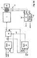
- FIG. 1 is a system diagram of an internal combustion engine with a storage injection system (Common rail) shown. This shows an internal combustion engine 1 with turbocharger and Intercooler 2, an electronic engine control unit 11, a first pump 4, a second Pump 6, a high-pressure accumulator (rail) 7, connected thereto injectors 8 and a
- Throttle valve 5 The first pump 4 delivers from a fuel tank 3 via the fuel the throttle valve 5 to the second pump 6. This in turn promotes the fuel below high pressure in the high pressure accumulator 7.
- the pressure level of the high pressure accumulator 7th is detected via a rail pressure sensor 10. Branch out of the high-pressure accumulator 7 Lines with connected injectors 8 for each cylinder Internal combustion engine 1 from.
- the electronic engine control unit 11 controls and regulates the state of Internal combustion engine 1.
- This has the usual components of a Microcomputer system, such as microprocessor, I / O devices, buffers and Memory blocks (EEPROM, RAM).
- EEPROM Electrically erasable programmable read-only memory
- In the memory modules are for the operation of the Internal combustion engine 1 relevant operating data in maps / curves applied.
- the in Figure 1 exemplified input variables of the electronic Engine control unit 11 are: maximum combustion pressure pIST (i), by means of pressure sensors 9 is measured, pressure pCR of the high-pressure accumulator 7, as well as the desired performance representative signal FW.
- the others for the operation of the internal combustion engine. 1 relevant input variables are represented by the reference symbol E.
- output variables A of the electronic engine control unit 11 are the drive signals for the injectors 8, according to the start of injection SB, a power-determining signal ve and the Drive signal ADV for the throttle valve 5 is shown. About the throttle valve 5 is the Feed to the second pump 6 is set.
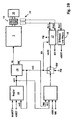
- FIG. 2A shows a block diagram of the control system of the internal combustion engine 1 with coupled loop structure. Shown are: a speed controller 14, a moment controller 15, a selection means 16 and the internal combustion engine 1 with the injection system.
- the internal combustion engine 1 drives via a clutch 13 to an engine load 12, for example a waterjet drive.
- the tooth angles Phi1 and Phi2 of the clutch 13 are of Speed sensors 19 detected. From the tooth angle Phi1 is via a function block Detecting / filtering 18 calculates the engine speed nMOT. From the two tooth angles Phi1 and Phi2, the engine torque MK is determined and evaluated in the diagnosis block 17.
- the input variables of the speed controller 14 are: the engine speed nMOT, a Speed difference dnMOT and a signal ve2, hereinafter referred to as the second signal.
- the speed difference is calculated from the engine speed nMOT and a Desired performance target value nMOT (SW).
- the second signal ve2 corresponds to the output signal of the torque controller 15.
- the output variable of the speed controller 14 is a first signal ve1, for example, an injection amount. This is on the Selection means 16 and the moment controller 15 out.
- the input variables of the torque controller 15 are: the engine torque MK, a difference torque dMK, the first signal ve1 and a regulator mode RM.
- the difference torque dMK is calculated from the deviation of the engine torque MK to a maximum allowable engine torque.
- the output signal of the moment controller 15 is the second signal ve2. This is on the selector 16 and the speed controller 14 out.
- the selection means 16 is determined which of the two controllers 14 and 15 respectively is dominant.
- the selection means 16 contains a minimum value selection.
- About the Minimum value selection is the first signal ve1 as a power-determining signal is set when the first signal ve1 is less than or equal to the second signal ve2.
- the controller mode RM is set to a first value. This corresponds to one Operation of the internal combustion engine in the speed mode.
- the second signal ve2 is set if it is smaller than the first signal ve1.
- the controller mode RM is set to a second value. This matches with an operation of the internal combustion engine in the torque-limiting mode.
- the Output signals of the selection means 16 are the power-determining signal ve and the Regulator mode RM.
- the power-determining signal ve is applied to the injector the internal combustion engine 1 out. Under power-determining signal ve is in the sense the invention to understand the injection quantity or the control path of a control rod.
- the diagnostic block 17 With recognition of implausible values of the engine torque MK, the diagnostic block 17 sets an error mode FM to one. Not Plausible values are present, for example, if the signal Phi1 due to Line interruption is missing. With setting of the error mode FM, the diagnosis block 17 leads the engine torque MK from the last plausible value according to a transient function Zero.
- the transition function can be used as a mathematical function or via a filter be executed. This transition function is shown in FIG. 5 and is connected explained with this. Due to the now decreasing engine torque MK calculates the Moment controller 15 a larger value of the second signal ve2. The diagnosis block 17 consequently acts indirectly on the second signal ve2.
- FIG. 2B shows an alternative to FIG. 2A.
- the software switch SW is the signal Error mode FM controlled. In normal operation, fault mode FM equals zero the software switch SW in the marked position.
- the second signal ve2 corresponds to the output signal of the torque controller 15.
- About a Feedback path RK is the second signal ve2 led to the diagnostic block 17. Of the Feedback path RK is only activated during normal operation.
- the value of the signal ve2D corresponds to the value of the second signal ve2.
- the diagnostic block 17 the error mode FM to one. This changes the position of the software switch SW. In this position, the second signal ve2 determined via the signal ve2D of the diagnostic block 17.
- the diagnosis block 17 performs the second Signal ve2 according to a transition function to a maximum value MAX.
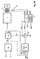
- FIG. 3A shows an alternative embodiment of the block diagram of FIG. 2A.
- the signal ve1 is transmitted via a Function block 20 depending on a desired performance, here accelerator pedal FP, calculated.
- the function block 20 includes the conversion of the accelerator pedal position in the first signal ve1. For this are corresponding characteristics including a limit curve (DBR curve) provided.
- the input quantities required for the conversion are represented by the reference E, for example engine speed nMOT, Charge air pressure pLL etc ..
- E for example engine speed nMOT, Charge air pressure pLL etc .
- the further structure and the functionality corresponds to the FIG. 2A, so that what is said there also applies here.
- FIG. 3B shows an alternative embodiment of the block diagram of FIG. 2B.
- the signal ve1 is transmitted via a Function block 20 depending on a desired performance, here accelerator pedal FP, calculated.
- the function block 20 includes the conversion of the accelerator pedal position in the first signal ve1. For this are corresponding characteristics including a limit curve (DBR curve) provided.
- the input quantities required for the conversion are represented by the reference E, for example engine speed nMOT, Charge air pressure pLL etc ..
- E for example engine speed nMOT, Charge air pressure pLL etc .
- the further structure and the functionality corresponds to the FIG. 2B, so that what is said there also applies here.
- the speed controller 14 is shown. This has an integral part and is exemplified as a PID controller. In practice, the speed controller can also be designed as a PI or PI (DT1) controller.
- the input variables of the speed controller 14 are: the speed difference dnMOT, the motor speed nMOT and the second signal ve2.
- the speed controller shown contains three functional blocks for calculating the P, I and D components, corresponding to the reference numerals 23 to 25.
- the function block 23 determines the P component ve1 (P) from an input variable EP and the rotational speed difference dnMOT , From the speed difference dnMOT, a first input signal ve (M) and a second input signal EI, the I-component ve1 (I) is calculated via the function block 24.
- the I component ve1 (I) is limited to the first input signal ve (M).
- the D-component ve1 (D) is calculated via the function block 25.
- the first input signal ve (M) corresponds to either the second signal ve2 or a signal ve1 (KF), depending on which signal has the lower significance.
- a first function block minimum value 22 is provided.
- the signal ve1 (KF) in turn is determined from the engine speed nMOT and other input variables E via maps 21. Also included is a limit curve (DBR curve).
- the other input variables are shown as collective reference symbol E.
- the input quantities E can be, for example, the charge air pressure pLL, the engine speed nMOT, etc. All three components, ie ve1 (P) and ve1 (I) and ve1 (D), are summed via a summation 26 to form a common signal ve1 (S). Via the second function block minimum value 27, the signal which has the lowest significance is then selected from this signal ve1 (S) and from the signal ve1 (KF). This signal corresponds to the first signal ve1.
- the second signal ve2 calculated by the torque controller 15 influences the calculation of the Integrating portion ve1 (I) of the speed controller 14.
- To a direct feedback of the Output of the speed controller 14 to the integrating portion ve1 (I) of the speed controller 14 via moment regulator 15 can avoid filtering the second signal ve2 be provided.
- the Error mode FM set. This causes the diagnosis via the second signal ve2 is increased.
- the signal ve1 (KF) to bear.
- the signal ve1 (KF) To the internal combustion engine before too high Protect values of the signal ve1 (KF), for example, to high fuel quantity, is via the maps 21, the signal ve1 (KF) adapted to smaller values. this happens by changing a limit curve (DBR curve) of the maps 21.
- DBR curve limit curve
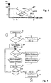
- FIG. 5 shows a time diagram. Here is on the abscissa the time or on the Ordinate the engine torque MK and the second signal ve2D plotted.
- solid line here is the measured engine torque MK shown.
- Dashed lines are the motor moments MK (1) output from the diagnostic block 17. or MK (2) shown.
- MK (2) shown.
- the alternative solution is shown at the diagnosis block 17 increases the second signal ve2 via the signal ve2D.
- the engine torque MK drops from the value of the point A to zero, for example, due to a sensor failure. From time t1 this remains then to zero.
- the diagnostic function recognizes that the engine torque MK is no longer plausible.
- the diagnostic function carries the value of the motor torque MK according to a transition function to the value zero, point B at time t3.
- Transition function can be executed in a first embodiment as a linear function MK (1) be.
- this transition function also according to a filter function MK (2), be executed with a parabolic course.
- the reduction of the Diagnosis block 17 output engine torque MK (1) or MK (2) effected in Consequently, an enlargement of the second signal ve2.
- the diagnostic block 17 thus acts indirectly to the second signal ve2.
- the diagnostic block 17 directly to the second signal ve2 acts, according to the figures 2B and 3B.
- This design is in Figure 5 shown as a dashed line.
- the signal ve2 according to the transition function from the value of the point C to the value of Point D, time t3, guided by the signal ve2D.
- the time course between the two points C and D can be used as a mathematical function or filter function be executed, waveform ve2 (1) and ve2 (2).
- FIG. 6 shows a program flow chart of the diagnostic function.
- step S1 initializes the function and sets initial values.
- the controller mode RM is queried.
- the regulator mode RM corresponds to 1, if the determination device, so the speed controller 14 or the functional block 20, is dominant. In this case, this mode remains received, step S8.
- the controller mode RM corresponds to 2 when the torque controller 15 is dominant.
- step S6 a change in the dominance of Moment controller 14 to the determination device.
- step S7 the Limit curve (DBR) of the maximum permissible first signal ve1 adapted. In practice this corresponds, for example, to the reduction in the maximum permissible injection quantity.
- step S9 the first signal ve1 is set as the power-determining signal ve. Thereafter, it is checked at step S10 whether the error is still present. If this is the case, then the process proceeds to step S5. If it is determined in step S10 that no If there is more error, the error mode is executed at step S11 at the elapse of a time step FM reset to zero. At step S12, it becomes the normal mode returned. Then the program flowchart branches to point A and moves to the Step S2 continues.
- DBR Limit curve
Landscapes
- Engineering & Computer Science (AREA)
- Chemical & Material Sciences (AREA)
- Combustion & Propulsion (AREA)
- Mechanical Engineering (AREA)
- General Engineering & Computer Science (AREA)
- Combined Controls Of Internal Combustion Engines (AREA)
- Electrical Control Of Air Or Fuel Supplied To Internal-Combustion Engine (AREA)
Abstract
Description
- Figur 1
- Ein Systemschaubild
- Figur 2A, 2B
- Regelkreisstruktur mit einem Drehzahl- und Moment-Regler
- Figur 3A, 3B
- Regelkreis mit Steuerung
- Figur 4
- Blockschaltbild Drehzahl-Regler
- Figur 5
- Ein Zeitdiagramm
- Figur 6
- Einen Programmablaufplan
Die Eingangsgrößen des Drehzahl-Reglers 14 sind: die Drehzahldifferenz dnMOT, die Motordrehzahl nMOT und das zweite Signal ve2.
Der dargestellte Drehzahl-Regler beinhaltet drei Funktionsblöcke zur Berechnung des P-, I-und D-Anteils, entsprechend den Bezugszeichen 23 bis 25. Über den Funktionsblock 23 wird aus einer Eingangsgröße EP und der Drehzahldifferenz dnMOT der P-Anteil ve1(P) ermittelt. Über den Funktionsblock 24 wird aus der Drehzahldifferenz dnMOT, einem ersten Eingangssignal ve(M) und einem zweiten Eingangssignals EI, der I-Anteil ve1(I) berechnet. Hierbei ist der I-Anteil ve1(I) auf das erste Eingangssignal ve(M) begrenzt. Über den Funktionsblock 25 wird aus der Drehzahldifferenz dnMOT und einer Eingangsgröße ED der D-Anteil ve1(D) berechnet. Das erste Eingangssignal ve(M) entspricht entweder dem zweiten Signal ve2 oder einem Signal ve1(KF), je nachdem, welches Signal die geringere Wertigkeit aufweist. Hierzu ist ein erster Funktionsblock Minimalwert 22 vorgesehen. Das Signal ve1(KF) wiederum wird aus der Motordrehzahl nMOT und weiteren Eingangsgrößen E über Kennfelder 21 bestimmt. Ebenfalls enthalten ist eine Grenzwert-Kurve (DBR-Kurve). Die weiteren Eingangsgrößen sind als Sammelbezugszeichen E dargestellt. Die Eingangsgrößen E können beispielsweise der Ladeluftdruck pLL, die Motordrehzahl nMOT usw. sein. Alle drei Anteile, d. h. ve1(P) und ve1(I) und ve1(D), werden über eine Summation 26 zu einem gemeinsamen Signal ve1(S) summiert. Über den zweiten Funktionsblock Minimalwert 27 wird sodann aus diesem Signal ve1(S) und aus dem Signal ve1(KF) dasjenige ausgewählt, welches die geringste Wertigkeit aufweist. Dieses Signal entspricht dem ersten Signal ve1.
- 1
- Brennkraftmaschine
- 2
- Turbolader
- 3
- Kraftstofftank
- 4
- erste Pumpe
- 5
- Drosselventil
- 6
- zweite Pumpe
- 7
- Hochdruckspeicher (Rail)
- 8
- Injektor
- 9
- Drucksensor
- 10
- Rail-Drucksensor
- 11
- Elektronisches Motorsteuergerät
- 12
- Motorlast
- 13
- Kupplung
- 14
- Drehzahl-Regler
- 15
- Moment-Regler
- 16
- Auswahlmittel
- 17
- Diagnoseblock
- 18
- Funktionsblock Erfassen/Filtem
- 19
- Drehzahlsensoren
- 20
- Funktionsblock
- 21
- Kennfelder
- 22
- Minimalwert
- 23
- Funktionsblock Berechnung P-Anteil
- 24
- Funktionsblock Berechnung I-Anteil
- 25
- Funktionsblock Berechnung D-Anteil
- 26
- Summation
- 27
- Minimalwert
Claims (8)
- Verfahren zur steuerung einer Brennkrtfmaschine (1), deren Leistung über ein leistungsbestimmendes Signal (ve) eingestellt wird, indem aus einer Sollwertvorgabe (FP, nMOT(SW)) mittels einer Bestimmungs-Einrichtung (14, 20) ein erstes Signal (ve1) bestimmt wird, aus dem Motor-Moment (MK) mittels eines Moment-Reglers (15) ein zweites Signal (ve2) bestimmt wird (ve2=f(MK)) und mittels eines Auswahlmittels (16) die Bestimmungs-Einrichtung oder der Moment-Regler (15) als dominant für das leistungsbestimmende Signal (ve) gesetzt wird (ve=ve1; ve=ve2), wobei bei nicht plausiblen Werten des Motor-Moments (MK) ein Fehlermodus (FM) gesetzt wird (FM=1), mit Setzen des Fehlermodus (FM=1) bei dominanter Bestimmungs-Einrichtung (14, 20) die Dominanz beibehalten wird und bei dominantem Moment-Regler (15) ein Wechsel in der Dominanz durchgeführt wird.
- Verfahren nach Anspruch 1, dadurch gekennzeichnet, dass bei gesetztem Fehlermodus (FM=1) der Wechsel der Dominanz vom Moment-Regler (15) zur Bestimmungs-Einrichtung (14, 20) gemäß einer Übergangsfunktion mittels eines Diagnoseblocks (17) durchgeführt wird.
- Verfahren nach Anspruch 2, dadurch gekennzeichnet, dass gemäß der Übergangsfunktion das Motor-Moment (MK) vom letzten plausiblen Wert auf Null (MK=0) geführt wird.
- Verfahren nach Anspruch 2, dadurch gekennzeichnet, dass gemäß der Übergangsfunktion das zweite Signal (ve2) vom letzten plausiblen Wert auf einen hohen Wert (ve2=MAX) geführt wird.
- Verfahren nach Anspruch 3 oder Anspruch 4, dadurch gekennzeichnet, dass die Übergangsfunktion als mathematische oder Filterfunktion ausgeführt wird.
- Verfahren nach einem der vorausgegangenen Ansprüche, dadurch gekennzeichnet, dass bei gesetztem Fehlermodus (FM=1) eine Grenzwertkurve (DBR) des maximal zulässigen ersten Signals (ve1) adaptiert wird.
- Verfahren nach Anspruch 6, dadurch gekennzeichnet, dass die Grenzwert-Kurve (DBR) hin zu kleineren Werten des ersten Signals (ve1) adaptiert wird.
- Verfahren nach einem der Ansprüche 1 bis 7, dadurch gekennzeichnet, dass der Fehlermodus (FM) zurückgesetzt wird (FM=0), wenn wieder plausible Werte des Motor-Moments (MK) detektiert werden und eine Zeitstufe (t) abgelaufen ist (t=0).
Applications Claiming Priority (3)
| Application Number | Priority Date | Filing Date | Title |
|---|---|---|---|
| DE10032110 | 2000-07-01 | ||
| DE10032110A DE10032110C2 (de) | 2000-07-01 | 2000-07-01 | Diagnosesystem für eine Brennkraftmaschine |
| PCT/EP2001/007393 WO2002002922A1 (de) | 2000-07-01 | 2001-06-28 | Diagnosefunktion für eine brennkraftmaschine |
Publications (2)
| Publication Number | Publication Date |
|---|---|
| EP1297250A1 EP1297250A1 (de) | 2003-04-02 |
| EP1297250B1 true EP1297250B1 (de) | 2005-11-23 |
Family
ID=7647494
Family Applications (1)
| Application Number | Title | Priority Date | Filing Date |
|---|---|---|---|
| EP01967103A Expired - Lifetime EP1297250B1 (de) | 2000-07-01 | 2001-06-28 | Diagnosefunktion für eine brennkraftmaschine |
Country Status (5)
| Country | Link |
|---|---|
| US (1) | US6863051B2 (de) |
| EP (1) | EP1297250B1 (de) |
| DE (2) | DE10032110C2 (de) |
| ES (1) | ES2250470T3 (de) |
| WO (1) | WO2002002922A1 (de) |
Families Citing this family (11)
| Publication number | Priority date | Publication date | Assignee | Title |
|---|---|---|---|---|
| DE10248633B4 (de) * | 2002-10-18 | 2006-01-12 | Mtu Friedrichshafen Gmbh | Verfahren zur Drehzahl-Regelung einer Antriebseinheit |
| DE102004011599B4 (de) * | 2004-03-10 | 2006-03-02 | Mtu Friedrichshafen Gmbh | Verfahren zur momentenorientierten Steuerung einer Brennkraftmaschine |
| JP4285437B2 (ja) * | 2005-04-27 | 2009-06-24 | トヨタ自動車株式会社 | 統合制御装置 |
| DE102006061889B3 (de) * | 2006-12-28 | 2008-03-27 | Siemens Ag | Verfahren und Vorrichtung zur Ermittlung einer optimierten Notlauffunktion bei einem mit einem Fehler behafteten Motor eines Kraftfahrzeugs |
| DE102007023553B3 (de) * | 2007-05-21 | 2008-12-04 | Continental Automotive Gmbh | Vorrichtung und Verfahren zum Steuern eines Antriebsaggregats |
| JP4971039B2 (ja) * | 2007-06-07 | 2012-07-11 | 本田技研工業株式会社 | モータ制御装置 |
| DE102007060670B4 (de) | 2007-12-17 | 2009-11-19 | Mtu Friedrichshafen Gmbh | Verfahren zur Regelung einer Brennkraftmaschine |
| FR2958611B1 (fr) * | 2010-04-12 | 2012-03-23 | Renault Sa | Procede de gestion d'un dispositif de repartition du couple moteur lors d'une defaillance de son bouton de selection. |
| CN105934572B (zh) | 2014-02-04 | 2019-05-03 | 日立汽车系统株式会社 | 车载控制装置 |
| JP6557564B2 (ja) * | 2015-09-16 | 2019-08-07 | ヤンマー株式会社 | エンジン装置 |
| JP2024005914A (ja) * | 2022-06-30 | 2024-01-17 | 日産自動車株式会社 | エンジン診断方法及びエンジン診断装置 |
Family Cites Families (8)
| Publication number | Priority date | Publication date | Assignee | Title |
|---|---|---|---|---|
| US5186081A (en) * | 1991-06-07 | 1993-02-16 | General Motors Corporation | Method of regulating supercharger boost pressure |
| JP3605221B2 (ja) * | 1996-03-19 | 2004-12-22 | 株式会社日立製作所 | 内燃機関の制御装置 |
| DE19624824A1 (de) * | 1996-06-21 | 1998-01-08 | Daimler Benz Ag | Sicherheitssystem für ein Kraftfahrzeug |
| DE19624822C1 (de) * | 1996-06-21 | 1997-08-14 | Daimler Benz Ag | Sicherheitssystem für ein Kraftfahrzeug |
| DE19739564A1 (de) * | 1997-09-10 | 1999-03-11 | Bosch Gmbh Robert | Verfahren und Vorrichtung zur Steuerung einer Antriebseinheit eines Fahrzeugs |
| DE19742083B4 (de) | 1997-09-24 | 2007-11-15 | Robert Bosch Gmbh | Verfahren und Vorrichtung zur Steuerung einer Brennkraftmaschine |
| DE19953767C2 (de) * | 1999-11-09 | 2002-03-28 | Mtu Friedrichshafen Gmbh | Regelsystem zum Schutz einer Brennkraftmaschine vor Überlast |
| DE10248633B4 (de) * | 2002-10-18 | 2006-01-12 | Mtu Friedrichshafen Gmbh | Verfahren zur Drehzahl-Regelung einer Antriebseinheit |
-
2000
- 2000-07-01 DE DE10032110A patent/DE10032110C2/de not_active Expired - Fee Related
-
2001
- 2001-06-28 EP EP01967103A patent/EP1297250B1/de not_active Expired - Lifetime
- 2001-06-28 DE DE50108180T patent/DE50108180D1/de not_active Expired - Lifetime
- 2001-06-28 ES ES01967103T patent/ES2250470T3/es not_active Expired - Lifetime
- 2001-06-28 US US10/312,840 patent/US6863051B2/en not_active Expired - Fee Related
- 2001-06-28 WO PCT/EP2001/007393 patent/WO2002002922A1/de not_active Ceased
Also Published As
| Publication number | Publication date |
|---|---|
| DE50108180D1 (de) | 2005-12-29 |
| DE10032110A1 (de) | 2002-01-24 |
| US20040055567A1 (en) | 2004-03-25 |
| DE10032110C2 (de) | 2002-10-31 |
| ES2250470T3 (es) | 2006-04-16 |
| WO2002002922A1 (de) | 2002-01-10 |
| EP1297250A1 (de) | 2003-04-02 |
| US6863051B2 (en) | 2005-03-08 |
Similar Documents
| Publication | Publication Date | Title |
|---|---|---|
| EP0826102B1 (de) | Verfahren und vorrichtung zur steuerung einer antriebseinheit eines fahrzeugs | |
| DE19536038B4 (de) | Verfahren und Vorrichtung zur Steuerung der Antriebseinheit eines Kraftfahrzeugs | |
| EP1062417B1 (de) | Verfahren und vorrichtung zum betreiben einer brennkraftmaschine | |
| DE19953767C2 (de) | Regelsystem zum Schutz einer Brennkraftmaschine vor Überlast | |
| DE19742083B4 (de) | Verfahren und Vorrichtung zur Steuerung einer Brennkraftmaschine | |
| EP1297250B1 (de) | Diagnosefunktion für eine brennkraftmaschine | |
| DE10215406A1 (de) | Verfahren und Vorrichtung zur Steuerung eines Motors | |
| EP1254310B1 (de) | Regelsystem für eine brennkraftmaschine | |
| DE19748355A1 (de) | Verfahren und Vorrichtung zur Steuerung der Antriebseinheit eines Fahrzeugs | |
| DE19836845B4 (de) | Verfahren und Vorrichtung zur Steuerung einer Antriebseinheit eines Kraftfahrzeugs | |
| EP1495222B1 (de) | Verfahren zum berwachen einer brennkraftmaschine | |
| DE4333896B4 (de) | Verfahren und Vorrichtung zur Steuerung einer Brennkraftmaschine | |
| EP0437559A1 (de) | Verfahren und vorrichtung zur steuerung und/oder regelung der motorleistung einer brennkraftmaschine eines kraftfahrzeugs. | |
| EP1882841A2 (de) | Verfahren zur Erkennung einer Voreinspritzung | |
| DE102007000064B4 (de) | Vorrichtung und Verfahren zur Brennstoffeinspritzung | |
| DE19937139C1 (de) | Verfahren und Einrichtung zur Steuerung einer Brennkraftmaschine | |
| DE3026150C2 (de) | ||
| EP1045966B1 (de) | Verfahren und vorrichtung zum betreiben und zur überwachung einer brennkraftmaschine | |
| DE3405495A1 (de) | Elektronisches steuersystem fuer die kraftstoffeinspritzung bei einer dieselbrennkraftmaschine | |
| EP0460126A1 (de) | System zur elektronischen steuerung und/oder regelung der leistung einer brennkraftmaschine eines kraftfahrzeugs. | |
| DE10058354A1 (de) | Verfahren und Vorrichtung zur Steuerung der Antriebseinheit eines Fahrzeugs | |
| EP1029168B1 (de) | Verfahren zum betreiben einer brennkraftmaschine insbesondere eines kraftfahrzeugs | |
| WO2013068141A1 (de) | Verfahren zur regelung der abgastemperatur einer direkteinspritzenden brennkraftmaschine | |
| DE102019003815A1 (de) | Verfahren zur Überwachung eines Injektors auf mechanische Schädigung | |
| DE102004029754A1 (de) | Verfahren zur Steuerung und Regelung einer Brennkraftmaschine mit Registeraufladung |
Legal Events
| Date | Code | Title | Description |
|---|---|---|---|
| PUAI | Public reference made under article 153(3) epc to a published international application that has entered the european phase |
Free format text: ORIGINAL CODE: 0009012 |
|
| 17P | Request for examination filed |
Effective date: 20021204 |
|
| AK | Designated contracting states |
Designated state(s): AT BE CH CY DE DK ES FI FR GB GR IE IT LI LU MC NL PT SE TR Kind code of ref document: A1 Designated state(s): AT BE CH CY DE DK ES FI FR GB GR IE IT LI LU MC NL PT SE TR |
|
| RBV | Designated contracting states (corrected) |
Designated state(s): AT BE CH CY DE ES FR GB IT LI |
|
| GRAP | Despatch of communication of intention to grant a patent |
Free format text: ORIGINAL CODE: EPIDOSNIGR1 |
|
| RBV | Designated contracting states (corrected) |
Designated state(s): DE ES FR GB IT |
|
| GRAS | Grant fee paid |
Free format text: ORIGINAL CODE: EPIDOSNIGR3 |
|
| GRAA | (expected) grant |
Free format text: ORIGINAL CODE: 0009210 |
|
| AK | Designated contracting states |
Kind code of ref document: B1 Designated state(s): DE ES FR GB IT |
|
| REG | Reference to a national code |
Ref country code: GB Ref legal event code: FG4D Free format text: NOT ENGLISH |
|
| REF | Corresponds to: |
Ref document number: 50108180 Country of ref document: DE Date of ref document: 20051229 Kind code of ref document: P |
|
| GBT | Gb: translation of ep patent filed (gb section 77(6)(a)/1977) |
Effective date: 20060208 |
|
| REG | Reference to a national code |
Ref country code: ES Ref legal event code: FG2A Ref document number: 2250470 Country of ref document: ES Kind code of ref document: T3 |
|
| ET | Fr: translation filed | ||
| PLBE | No opposition filed within time limit |
Free format text: ORIGINAL CODE: 0009261 |
|
| STAA | Information on the status of an ep patent application or granted ep patent |
Free format text: STATUS: NO OPPOSITION FILED WITHIN TIME LIMIT |
|
| 26N | No opposition filed |
Effective date: 20060824 |
|
| PGFP | Annual fee paid to national office [announced via postgrant information from national office to epo] |
Ref country code: ES Payment date: 20120627 Year of fee payment: 12 |
|
| PGFP | Annual fee paid to national office [announced via postgrant information from national office to epo] |
Ref country code: GB Payment date: 20130619 Year of fee payment: 13 Ref country code: DE Payment date: 20130620 Year of fee payment: 13 |
|
| PGFP | Annual fee paid to national office [announced via postgrant information from national office to epo] |
Ref country code: IT Payment date: 20130626 Year of fee payment: 13 Ref country code: FR Payment date: 20130703 Year of fee payment: 13 |
|
| REG | Reference to a national code |
Ref country code: DE Ref legal event code: R119 Ref document number: 50108180 Country of ref document: DE |
|
| GBPC | Gb: european patent ceased through non-payment of renewal fee |
Effective date: 20140628 |
|
| REG | Reference to a national code |
Ref country code: FR Ref legal event code: ST Effective date: 20150227 |
|
| REG | Reference to a national code |
Ref country code: DE Ref legal event code: R119 Ref document number: 50108180 Country of ref document: DE Effective date: 20150101 |
|
| PG25 | Lapsed in a contracting state [announced via postgrant information from national office to epo] |
Ref country code: IT Free format text: LAPSE BECAUSE OF NON-PAYMENT OF DUE FEES Effective date: 20140628 Ref country code: DE Free format text: LAPSE BECAUSE OF NON-PAYMENT OF DUE FEES Effective date: 20150101 |
|
| PG25 | Lapsed in a contracting state [announced via postgrant information from national office to epo] |
Ref country code: GB Free format text: LAPSE BECAUSE OF NON-PAYMENT OF DUE FEES Effective date: 20140628 Ref country code: FR Free format text: LAPSE BECAUSE OF NON-PAYMENT OF DUE FEES Effective date: 20140630 |
|
| REG | Reference to a national code |
Ref country code: ES Ref legal event code: FD2A Effective date: 20150729 |
|
| PG25 | Lapsed in a contracting state [announced via postgrant information from national office to epo] |
Ref country code: ES Free format text: LAPSE BECAUSE OF NON-PAYMENT OF DUE FEES Effective date: 20140629 |