EP1296412B1 - Einparkhilfsvorrichtung für Kraftfahrzeuge - Google Patents
Einparkhilfsvorrichtung für Kraftfahrzeuge Download PDFInfo
- Publication number
- EP1296412B1 EP1296412B1 EP02014501A EP02014501A EP1296412B1 EP 1296412 B1 EP1296412 B1 EP 1296412B1 EP 02014501 A EP02014501 A EP 02014501A EP 02014501 A EP02014501 A EP 02014501A EP 1296412 B1 EP1296412 B1 EP 1296412B1
- Authority
- EP
- European Patent Office
- Prior art keywords
- sensors
- sensor
- parking space
- vehicle
- distance
- Prior art date
- Legal status (The legal status is an assumption and is not a legal conclusion. Google has not performed a legal analysis and makes no representation as to the accuracy of the status listed.)
- Expired - Lifetime
Links
- 230000005855 radiation Effects 0.000 claims description 2
- 238000005259 measurement Methods 0.000 description 5
- 230000001419 dependent effect Effects 0.000 description 3
- 238000001514 detection method Methods 0.000 description 2
- 238000011156 evaluation Methods 0.000 description 2
- 238000009434 installation Methods 0.000 description 2
- 244000025254 Cannabis sativa Species 0.000 description 1
- 238000012937 correction Methods 0.000 description 1
- 238000011161 development Methods 0.000 description 1
- 230000004069 differentiation Effects 0.000 description 1
- 238000002592 echocardiography Methods 0.000 description 1
- 238000000034 method Methods 0.000 description 1
- 238000002604 ultrasonography Methods 0.000 description 1
Images
Classifications
-
- B—PERFORMING OPERATIONS; TRANSPORTING
- B60—VEHICLES IN GENERAL
- B60Q—ARRANGEMENT OF SIGNALLING OR LIGHTING DEVICES, THE MOUNTING OR SUPPORTING THEREOF OR CIRCUITS THEREFOR, FOR VEHICLES IN GENERAL
- B60Q9/00—Arrangement or adaptation of signal devices not provided for in one of main groups B60Q1/00 - B60Q7/00, e.g. haptic signalling
- B60Q9/002—Arrangement or adaptation of signal devices not provided for in one of main groups B60Q1/00 - B60Q7/00, e.g. haptic signalling for parking purposes, e.g. for warning the driver that his vehicle has contacted or is about to contact an obstacle
- B60Q9/004—Arrangement or adaptation of signal devices not provided for in one of main groups B60Q1/00 - B60Q7/00, e.g. haptic signalling for parking purposes, e.g. for warning the driver that his vehicle has contacted or is about to contact an obstacle using wave sensors
- B60Q9/006—Arrangement or adaptation of signal devices not provided for in one of main groups B60Q1/00 - B60Q7/00, e.g. haptic signalling for parking purposes, e.g. for warning the driver that his vehicle has contacted or is about to contact an obstacle using wave sensors using a distance sensor
-
- G—PHYSICS
- G01—MEASURING; TESTING
- G01S—RADIO DIRECTION-FINDING; RADIO NAVIGATION; DETERMINING DISTANCE OR VELOCITY BY USE OF RADIO WAVES; LOCATING OR PRESENCE-DETECTING BY USE OF THE REFLECTION OR RERADIATION OF RADIO WAVES; ANALOGOUS ARRANGEMENTS USING OTHER WAVES
- G01S13/00—Systems using the reflection or reradiation of radio waves, e.g. radar systems; Analogous systems using reflection or reradiation of waves whose nature or wavelength is irrelevant or unspecified
- G01S13/88—Radar or analogous systems specially adapted for specific applications
- G01S13/93—Radar or analogous systems specially adapted for specific applications for anti-collision purposes
- G01S13/931—Radar or analogous systems specially adapted for specific applications for anti-collision purposes of land vehicles
-
- H—ELECTRICITY
- H01—ELECTRIC ELEMENTS
- H01Q—ANTENNAS, i.e. RADIO AERIALS
- H01Q1/00—Details of, or arrangements associated with, antennas
- H01Q1/27—Adaptation for use in or on movable bodies
- H01Q1/32—Adaptation for use in or on road or rail vehicles
- H01Q1/3208—Adaptation for use in or on road or rail vehicles characterised by the application wherein the antenna is used
- H01Q1/3233—Adaptation for use in or on road or rail vehicles characterised by the application wherein the antenna is used particular used as part of a sensor or in a security system, e.g. for automotive radar, navigation systems
-
- H—ELECTRICITY
- H01—ELECTRIC ELEMENTS
- H01Q—ANTENNAS, i.e. RADIO AERIALS
- H01Q1/00—Details of, or arrangements associated with, antennas
- H01Q1/27—Adaptation for use in or on movable bodies
- H01Q1/32—Adaptation for use in or on road or rail vehicles
- H01Q1/325—Adaptation for use in or on road or rail vehicles characterised by the location of the antenna on the vehicle
- H01Q1/3283—Adaptation for use in or on road or rail vehicles characterised by the location of the antenna on the vehicle side-mounted antennas, e.g. bumper-mounted, door-mounted
-
- G—PHYSICS
- G01—MEASURING; TESTING
- G01S—RADIO DIRECTION-FINDING; RADIO NAVIGATION; DETERMINING DISTANCE OR VELOCITY BY USE OF RADIO WAVES; LOCATING OR PRESENCE-DETECTING BY USE OF THE REFLECTION OR RERADIATION OF RADIO WAVES; ANALOGOUS ARRANGEMENTS USING OTHER WAVES
- G01S13/00—Systems using the reflection or reradiation of radio waves, e.g. radar systems; Analogous systems using reflection or reradiation of waves whose nature or wavelength is irrelevant or unspecified
- G01S13/88—Radar or analogous systems specially adapted for specific applications
- G01S13/93—Radar or analogous systems specially adapted for specific applications for anti-collision purposes
- G01S13/931—Radar or analogous systems specially adapted for specific applications for anti-collision purposes of land vehicles
- G01S2013/9314—Parking operations
-
- G—PHYSICS
- G01—MEASURING; TESTING
- G01S—RADIO DIRECTION-FINDING; RADIO NAVIGATION; DETERMINING DISTANCE OR VELOCITY BY USE OF RADIO WAVES; LOCATING OR PRESENCE-DETECTING BY USE OF THE REFLECTION OR RERADIATION OF RADIO WAVES; ANALOGOUS ARRANGEMENTS USING OTHER WAVES
- G01S13/00—Systems using the reflection or reradiation of radio waves, e.g. radar systems; Analogous systems using reflection or reradiation of waves whose nature or wavelength is irrelevant or unspecified
- G01S13/88—Radar or analogous systems specially adapted for specific applications
- G01S13/93—Radar or analogous systems specially adapted for specific applications for anti-collision purposes
- G01S13/931—Radar or analogous systems specially adapted for specific applications for anti-collision purposes of land vehicles
- G01S2013/9324—Alternative operation using ultrasonic waves
-
- G—PHYSICS
- G01—MEASURING; TESTING
- G01S—RADIO DIRECTION-FINDING; RADIO NAVIGATION; DETERMINING DISTANCE OR VELOCITY BY USE OF RADIO WAVES; LOCATING OR PRESENCE-DETECTING BY USE OF THE REFLECTION OR RERADIATION OF RADIO WAVES; ANALOGOUS ARRANGEMENTS USING OTHER WAVES
- G01S13/00—Systems using the reflection or reradiation of radio waves, e.g. radar systems; Analogous systems using reflection or reradiation of waves whose nature or wavelength is irrelevant or unspecified
- G01S13/88—Radar or analogous systems specially adapted for specific applications
- G01S13/93—Radar or analogous systems specially adapted for specific applications for anti-collision purposes
- G01S13/931—Radar or analogous systems specially adapted for specific applications for anti-collision purposes of land vehicles
- G01S2013/9327—Sensor installation details
- G01S2013/93274—Sensor installation details on the side of the vehicles
-
- G—PHYSICS
- G01—MEASURING; TESTING
- G01S—RADIO DIRECTION-FINDING; RADIO NAVIGATION; DETERMINING DISTANCE OR VELOCITY BY USE OF RADIO WAVES; LOCATING OR PRESENCE-DETECTING BY USE OF THE REFLECTION OR RERADIATION OF RADIO WAVES; ANALOGOUS ARRANGEMENTS USING OTHER WAVES
- G01S15/00—Systems using the reflection or reradiation of acoustic waves, e.g. sonar systems
- G01S15/88—Sonar systems specially adapted for specific applications
- G01S15/93—Sonar systems specially adapted for specific applications for anti-collision purposes
- G01S15/931—Sonar systems specially adapted for specific applications for anti-collision purposes of land vehicles
- G01S2015/932—Sonar systems specially adapted for specific applications for anti-collision purposes of land vehicles for parking operations
- G01S2015/933—Sonar systems specially adapted for specific applications for anti-collision purposes of land vehicles for parking operations for measuring the dimensions of the parking space when driving past
- G01S2015/934—Sonar systems specially adapted for specific applications for anti-collision purposes of land vehicles for parking operations for measuring the dimensions of the parking space when driving past for measuring the depth, i.e. width, not length, of the parking space
-
- G—PHYSICS
- G01—MEASURING; TESTING
- G01S—RADIO DIRECTION-FINDING; RADIO NAVIGATION; DETERMINING DISTANCE OR VELOCITY BY USE OF RADIO WAVES; LOCATING OR PRESENCE-DETECTING BY USE OF THE REFLECTION OR RERADIATION OF RADIO WAVES; ANALOGOUS ARRANGEMENTS USING OTHER WAVES
- G01S15/00—Systems using the reflection or reradiation of acoustic waves, e.g. sonar systems
- G01S15/88—Sonar systems specially adapted for specific applications
- G01S15/93—Sonar systems specially adapted for specific applications for anti-collision purposes
- G01S15/931—Sonar systems specially adapted for specific applications for anti-collision purposes of land vehicles
- G01S2015/932—Sonar systems specially adapted for specific applications for anti-collision purposes of land vehicles for parking operations
- G01S2015/933—Sonar systems specially adapted for specific applications for anti-collision purposes of land vehicles for parking operations for measuring the dimensions of the parking space when driving past
- G01S2015/935—Sonar systems specially adapted for specific applications for anti-collision purposes of land vehicles for parking operations for measuring the dimensions of the parking space when driving past for measuring the contour, e.g. a trajectory of measurement points, representing the boundary of the parking space
Definitions
- the invention relates to a Einparkosvorraum for motor vehicles with the features specified in the preamble of claim 1.
- Various known Einparkosvoriquesen provide for the measurement of parking spaces at least one on the curb-facing vehicle side mounted distance sensor, which perpendicular to the direction when driving past the length (see DE 37 28 948 A and EP 305 907 A1) and optionally at depth-limited parking spaces (z. B. by curb) and their depth determined.
- Ultrasonic or radar distance measuring systems eg 24 GHz systems
- conical beams are used as distance sensors.
- opening angles of about 60 ° are used in the radar systems, and smaller angles are also suitable for the less expensive ultrasound systems.
- Distance sensor is to be understood as meaning a transmitter / receiver device with downstream evaluation electronics.
- the described distance sensors work with relatively large wavelengths (eg 12.5 mm @ 24 GHz and 8.6 mm @ 40 kHz US).
- irradiated objects having a roughness below this wavelength reflect like ideal mirrors.
- the parking space measurement involves two fundamental problems: First, the geometric shape of the parking space boundaries (box-shaped or rounded) influences the longitudinal measurement, second, the indistinguishability between relevant raised (eg posts or vehicles) and non-relevant road-related objects (pebbles, grass stones) added. A differentiation between these classes of objects can not be achieved by triangulation of horizontally juxtaposed sensors.
- the detection of the parking space depth requires relatively large opening angle of the sensor lobe (s).
- the position or directional accuracy is reduced for the longitudinal measurement.
- the front side of the rear boundary is still seen in rear view if the axis of the sensor lobe has already left it behind, the rear of the front boundary is already detected in advance, before the axis of the sensor lobe is at its height. This results in the measured gap length being smaller than it is, the more serious the wider the transmitter beam lobe is chosen.
- US Pat. No. 6,265,968 B1 discloses a device with which a parking space can be optically scanned. By appropriate signal evaluation is to be able to distinguish between the parking space limiting, stationary, and passing objects.
- EP 1 068 992 A2 shows a parking assist device for motor vehicles, in which a transmitter arranged on the vehicle rear side scans the object located behind the vehicle horizontally and vertically. The result is displayed on a screen.
- the invention has for its object to provide a Einparkosvorraum of the aforementioned type, which enables a reliable statement about the actual shape of a parking space with little effort.
- the sensor 1 has in the horizontal direction a narrow (about 10 ° - 20 °), in the vertical direction a wide (about 30 ° - 60 °) beam lobe 1 '.
- the beam lobe can be approximated as a surface whose normal runs horizontally in the direction of travel.
- the sensor 2 has the same geometric configuration, but rotated by 90 ° (beam lobe 2 ').
- the axes of both sensors show horizontally parallel at right angles to the direction of travel.
- the surface normals of the two sensors are perpendicular to each other. Instead of the illustrated embodiment, the surface normals may also be inclined at 45 ° to the direction of travel
- the vertical orientation of the center axes of the beam lobes 1 'and 2' is dependent on the installation height of the sensors 1 and 2 and is ideally chosen so that the lobe 2 'the road surface only at a greater distance from the vehicle with noticeable intensity. In contrast to the o.g. known systems with a conical lobe, this results in the advantage of ground echoes, e.g. by gravel, Gullis or other road-related objects do not occur. The beam lobe 2 'looks over these objects and only detects objects that have a greater distance from the vehicle. Depending on the installation height, it is thus possible not to detect a curb or only from a certain height.
- the beam 1 ' which extends in the vertical direction, strikes the road surface at a considerable distance even at a short distance from the sensor.
- the distance values of these objects fluctuate i.a. depending on the distribution of the objects on the ground, whereas curbs lead to uniform distance values over longer driving distances of the vehicle. If, therefore, the sensor 1 determines objects that fluctuate in terms of distance, the sensor 2, which overlooks these objects, does not determine object information or even distance information at a greater distance, it can be assumed that the parking space is accessible for parking.
- the sensor 1 When passing them, the sensor 1 provides almost the same object information as the sensor 2, since the area of the side surface irradiated in the reflection direction the parking space limitations are as good as not different for the two sensors. After passing the front side, there are virtually no surface elements in the reflection direction for both sensors, and the intensity of the distance signals drops abruptly in both sensors.
- the backscatter intensity of the sensor 1 drops considerably faster than that of the sensor 2 after passing through its end face due to the bundling which is stronger in the horizontal direction, which detects the rounding in retrospect even longer with its horizontally wide lobe.
- Avoidance of mutual influence of both sensors can be ensured by choosing slightly different operating frequencies, alternating mode or suitable modulation method.
Landscapes
- Engineering & Computer Science (AREA)
- Remote Sensing (AREA)
- Radar, Positioning & Navigation (AREA)
- Physics & Mathematics (AREA)
- Computer Networks & Wireless Communication (AREA)
- Electromagnetism (AREA)
- Computer Security & Cryptography (AREA)
- General Physics & Mathematics (AREA)
- Transportation (AREA)
- Human Computer Interaction (AREA)
- Mechanical Engineering (AREA)
- Measurement Of Velocity Or Position Using Acoustic Or Ultrasonic Waves (AREA)
- Radar Systems Or Details Thereof (AREA)
- Arrangement Or Mounting Of Propulsion Units For Vehicles (AREA)
- Electric Propulsion And Braking For Vehicles (AREA)
Description
- Die Erfindung bezieht sich auf eine Einparkhilfsvorrichtung für Kraftfahrzeuge mit den im Oberbegriff des Patentanspruchs 1 angegeben Merkmalen.
- Verschiedene bekannte Einparkhilfsvorrichtungen sehen zur Vermessung von Parklücken mindestens einen an der dem Bordstein zugewandten Fahrzeugseite montierten Abstandssensor vor, welcher senkrecht zur Fahrtrichtung beim Vorbeifahren die Länge (vgl. DE 37 28 948 A und EP 305 907 A1) und optional bei tiefenbegrenzten Parklücken (z. B. durch Bordstein) auch deren Tiefe ermittelt. Als Abstandssensoren dienen dabei Ultraschall- oder Radar-Abstandsmesssysteme (z. B. 24 GHz-Systeme) mit konischen Strahlenkeulen. Aus Gründen der Antennen-Querschnittsfläche finden bei den Radarsystemen Öffnungswinkel von ca. 60 DEG Anwendung, bei den kostengünstigeren Ultraschallsystemen kommen auch kleinere Winkel in Betracht. Unter Abstandssensor ist dabei eine Sender-/Empfängereinrichtung mit nachgeschalteter Auswerteelektronik zu verstehen.
- Im Gegensatz zu Licht arbeiten die beschriebenen Abstandssensoren mit relativ großen Wellenlängen (z. B. 12,5mm@24GHz und 8,6mm@40kHz US). Damit reflektieren bestrahlte Objekte, welche ein Rauigkeitsmass unterhalb dieser Wellenlänge aufweisen, wie ideale Spiegel.
- Da die Sensoren nur Abstands-, nicht aber Richtungsinformation liefern, müssen im Strahlkegel erfasste Objekte auf die Strahlachse positioniert werden. Die Abschätzung der Richtung mittels Triangulation bei Verwendung zweier oder mehrerer Sensoren gelingt aber nur dann, falls genau dieselbe Objektstelle vermessen wird. Dies geht aber mit spiegelartig reflektierenden Objekten prinzipiell nicht, da hier nur senkrecht auftreffende Strahlung in den Empfänger zurückreflektiert wird.
- Die Parklückenvermessung beinhaltet zwei grundsätzliche Probleme: Erstens beeinflusst die geometrische Form der Parklückenbegrenzungen (kastenförmig oder abgerundet) die Längsvermessung, zweitens kommt die Ununterscheidbarkeit zwischen relevanten erhabenen (z. B. Pfosten oder Fahrzeuge) und nichtrelevanten fahrbahnbezogenen Objekten (Steinchen, Rasensteine) hinzu. Eine Differenzierung zwischen diesen Objektklassen gelingt auch nicht durch Triangulation horizontal nebeneinander angeordneter Sensoren.
- Die Erfassung der Parklückentiefe (Bordsteindetektion) bedingt relativ große Öffnungswinkel der Sensorkeule(n). Damit wird für die Längsvermessung die Positions- bzw. Richtungsgenauigkeit aber reduziert. Bei verrundeten Parklückenbegrenzungen wird die Stirnseite der hinteren Begrenzung in Rückwärtssicht noch gesehen, wenn die Achse der Sensorkeule sie schon hinter sich gelassen hat, die Rückseite der vorderen Begrenzung wird in Vorausschau schon detektiert, bevor die Achse der Sensorkeule auf ihrer Höhe ist. Dies führt dazu, dass die gemessene Lückenlänge geringer ausfällt als sie ist, mit um so gravierenderem Ausmass, je breiter die Sender-Strahlenkeule gewählt wird.
- In diesem Zusammenhang ist es aus der DE 201 05 340 U1 bekannt, bei Überfahren einer Parklücke mit mehreren nacheinander erzeugter 2-dimensionaler Lichtfächer die Parklücke auszumessen und unter Berücksichtigung des zurückgelegten Weges ein 3-dimensionales Abbild der Parklücke zu reproduzieren.
- Ferner ergibt sich aus der US 6 265 968 B1 eine Einrichtung, mit der eine Parklücke optisch gescannt werden kann. Durch entsprechende Signalauswertung soll dabei zwischen die Parklücke begrenzenden, stehenden, und vorbeifahrenden Objekten unterschieden werden können.
- Schließlich zeigt die EP 1 068 992 A2 eine Einparkhilfsvorrichtung für Kraftfahrzeuge, bei der ein an der Fahrzeugrückseite angeordneter Sender das hinter dem Fahrzeug befindliche Objekt horizontal und vertikal abrastert. Das Ergebnis wird auf einem Bildschirm dargestellt.
- Der Erfindung liegt die Aufgabe zugrunde, eine Einparkhilfsvorrichtung der eingangs genannten Art zu schaffen, die mit geringem Aufwand eine zuverlässige Aussage über die tatsächliche Form einer Parklücke ermöglicht.
- Die Erfindung löst diese Aufgabe mit den Merkmalen des Patentanspruchs 1.
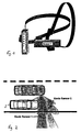
- Eine benachbarte, vorzugsweise in einem gemeinsamen Gehäuse an einem vorderen Eckpunkt des Kraftfahrzeugs sitzende Anordnung zweier Abstands-Sensoren 1 und 2, die zwei Sendesignale unterschiedlicher Strahlengeometrie liefern und zusammen eine "Kreuzkeule" erzeugen, kann die beiden genannten Grundprobleme deutlich abmindern. Aus Kostengründen kommen dabei vorzugsweise Ultraschallsensoren in Betracht, das Prinzip gilt analog natürlich aber auch für Radarsensoren. Die Anordnung ist anhand von Figur 1 veranschaulicht.
- Der Sensor 1 besitzt in horizontaler Richtung eine schmale (ca. 10° - 20°), in vertikaler Richtung eine breite (ca. 30° - 60°) Strahlkeule 1'. Näherungsweise kann die Strahlkeule als Fläche angenähert werden, deren Normalen horizontal in Fahrtrichtung verläuft. Der Sensor 2 weist dieselbe geometrische Konfiguration auf, jedoch um 90° verdreht (Strahlkeule 2'). Die Achsen beider Sensoren zeigen horizontal parallel rechtwinklig zur Fahrtrichtung. Die Flächennormalen der beiden Sensoren stehen senkrecht aufeinander. Anstelle der dargestellten Ausführung können die Flächennormalen auch um jeweils 45° gegen die Fahrtrichtung geneigt sein
- Die vertikale Ausrichtung der Mittelachsen der Strahlkeulen 1' und 2' ist abhängig von der Einbauhöhe der Sensoren 1 und 2 und wird idealer Weise so gewählt, dass die Keule 2' die Fahrbahnoberfläche erst in größerer Entfernung vom Fahrzeug mit merklicher Intensität triff. Im Gegensatz zu den o.g. bekannten Systemen mit konischer Strahlkeule ergibt sich dadurch der Vorteil, Bodenechos z.B. durch Schotter, Gullis oder andere fahrbahnbezogenen Objekte nicht auftreten zu lassen. Die Strahlkeule 2' sieht über diese Objekte hinweg und detektiert erst Objekte, die einen größeren Abstand vom Fahrzeug besitzen. Je nach Einbauhöhe ist es damit möglich, einen Bordstein nicht oder erst ab einer bestimmten Höhe zu detektieren.
- Die in vertikaler Richtung ausgedehnte Strahlenkeule 1' trifft schon in kurzem Abstand vom Sensor mit merklicher Intensität auf die Fahrbahnfläche. So können z.B. sich dort befindliche Steinchen als vom Sensor 1 detektierte Objekte bemerkbar machen. Die Abstandswerte dieser Objekte schwanken i.a. je nach Verteilung der Objekte auf dem Boden, wogegen Bordsteine über längere Vorbeifahrstrecken des Fahrzeuges hinweg zu gleichmäßigen Abstandswerten führen. Sofern also der Sensor 1 abstandsmäßig fluktuierende Objekte ermittelt, der Sensor 2, welcher über diese Objekte hinwegsieht, keine Objektinformation oder gleichmäßige Abstandsinformation in größerer Entfernung ermittelt, kann davon ausgegangen werden, dass die Parklücke zum Einparken zugänglich ist.
- Durch den Vergleich der entfernungsabhängigen Rückstreuamplituden beider Sensoren 1 und 2 während der Vorbeifahrt an einem Hindernis bzw. wie in Fig. 2 dargestellt einem abgestellten Fahrzeug 3 kann ferner die Formgestalt der Parklückenbegrenzungen (eckig bzw. abgerundet) bestimmt werden.
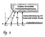
Anhand von Figur 3 ist die Arbeitsweise der erfindungsgemäßen Vorrichtung weiter erläutert. - Es seien kastenförmige hintere Parklückenbegrenzungen angenommen. Bei der Vorbeifahrt an ihnen liefert der Sensor 1 nahezu dieselbe Objektinformation wie der Sensor 2, da der in Reflexionsrichtung bestrahlte Flächenbereich der Seitenfläche der Parklückenbegrenzungen sich für die beiden Sensoren so gut wie nicht unterscheidet. Nach Passieren der Vorderseite befinden sich für beide Sensoren dann praktisch keine Flächenelemente mehr in Reflexionsrichtung, die Intensität der Abstandssignale fällt bei beiden Sensoren abrupt ab.
- Ist die Vorderseite der hinteren Parklückenbegrenzung aber abgerundet, fällt nach dem Passieren ihrer Stirnfläche die Rückstreuintensität des Sensors 1 wegen der in horizontaler Richtung stärkeren Bündelung wesentlich schneller ab als die des Sensors 2, der mit seiner horizontal breiten Keule die Verrundung in Rückschau noch länger detektiert.
- Bei S beginnt die Parklücke. Die dort gemessene Entfernung D ist wegen der Rückschau schon größer als D0. Der Sensor 1 mit horizontal schmaler Keule findet je nach der geometrischen Formgestalt dort schon keine Flächenanteile in Reflexionsstellung mehr vor, zugleich steigt aber das Bodensignal (Clutter) aus Entfernungen > D0 deutlich an. Die wegabhängige Entwicklung dieses Bodensignals bietet damit eine Korrekturmöglichkeit zu der Bestimmung des Endes der Parklückenbegrenzung.
- Entsprechendes gilt für die Erfassung der Rückseite der vorderen Parklückenbegrenzung.
- Eine Vermeidung gegenseitiger Beeinflussung beider Sensoren kann durch Wahl leicht unterschiedlicher Betriebsfrequenzen, alternierender Betriebsart oder geeigneter Modulationsverfahren gewährleistet werden.
- Durch eine Kombination zweier billiger Sensoren 1 und 2 wird ein Funktionsumfang erzielt, der alternativ nur mit bedeutend aufwendigerer und teurerer Sensorik (Multibeam- oder Scanner-Systeme) zu erzielen ist. Die Messgenauigkeit für die Parklückenlänge wird wesentlich weniger durch unterschiedliche geometrische Parklücken-Begrenzungsformen beeinflusst.
- Damit steigt der Nutzungsgrad von auf dieser Vermessung aufbauenden Fahrer-Assistenzsysteme, mit deren Hilfe beispielsweise der Parkiervorgang unterstützt bzw. selbsttätig durchgeführt wird.
Claims (4)
- Einparkhilfsvorrichtung für Kraftfahrzeuge mit mindestens einem an der Fahrzeugaußenseite angeordneten Sender (Sensoren 1 und 2) für ein zumindest annähernd senkrecht zur Fahrzeuglängsachse abgestrahltes, auf einen kleinen Ausstrahlwinkelbereich beschränktes Sendesignal und einen zugeordneten Empfänger für das Reflexsignal, dadurch gekennzeichnet, dass das Sendesignal aus zwei Teilstrahlen (Strahlkeulen 1' und 2') gebildet ist, die eine annähernd flächenförmige Abstrahlcharakteristik besitzen, wobei die beiden Flächen zumindest annähernd senkrecht zueinander stehen.
- Vorrichtung nach Anspruch 1, dadurch gekennzeichnet, dass eine der Flächennormalen horizontal und die andere vertikal orientiert ist.
- Vorrichtung nach Anspruch 1 oder 2, dadurch gekennzeichnet, dass die beiden Teilstrahlen in Sendern erzeugt sind, die sich in einem gemeinsamen Gehäuse befinden.
- Vorrichtung nach einem der Ansprüche 1 bis 3, dadurch gekennzeichnet, dass der/die Sender an einem vorderen Eckpunkt des Kraftfahrzeugs sitzt/sitzen.
Applications Claiming Priority (2)
| Application Number | Priority Date | Filing Date | Title |
|---|---|---|---|
| DE10146712A DE10146712A1 (de) | 2001-09-21 | 2001-09-21 | Einparkhilfsvorrichtung für Kraftfahrzeuge |
| DE10146712 | 2001-09-21 |
Publications (3)
| Publication Number | Publication Date |
|---|---|
| EP1296412A2 EP1296412A2 (de) | 2003-03-26 |
| EP1296412A3 EP1296412A3 (de) | 2004-01-07 |
| EP1296412B1 true EP1296412B1 (de) | 2006-09-27 |
Family
ID=7699889
Family Applications (1)
| Application Number | Title | Priority Date | Filing Date |
|---|---|---|---|
| EP02014501A Expired - Lifetime EP1296412B1 (de) | 2001-09-21 | 2002-06-29 | Einparkhilfsvorrichtung für Kraftfahrzeuge |
Country Status (4)
| Country | Link |
|---|---|
| US (1) | US6819284B2 (de) |
| EP (1) | EP1296412B1 (de) |
| DE (2) | DE10146712A1 (de) |
| ES (1) | ES2273949T3 (de) |
Families Citing this family (31)
| Publication number | Priority date | Publication date | Assignee | Title |
|---|---|---|---|---|
| DE10220837A1 (de) * | 2002-05-08 | 2003-11-27 | Daimler Chrysler Ag | Vorrichtung zur Parklückensuche mittels Radar |
| US7290161B2 (en) | 2003-03-24 | 2007-10-30 | Intel Corporation | Reducing CPU and bus power when running in power-save modes |
| US7888485B2 (en) * | 2003-03-26 | 2011-02-15 | Georgetown University | Anti-pleiotrophin antibodies and methods of use thereof |
| DE10325709A1 (de) * | 2003-06-06 | 2004-12-23 | Valeo Schalter Und Sensoren Gmbh | Vorrichtung und Verfahren zum Erkennen des Konturverlaufes eines Hindernisses |
| DE10326385A1 (de) * | 2003-06-12 | 2004-12-30 | Valeo Schalter Und Sensoren Gmbh | Einparkhilfevorrichtung und Verfahren zur Ermittlung der Länge einer Parklücke |
| DE10339645A1 (de) * | 2003-08-28 | 2005-04-14 | Robert Bosch Gmbh | Verfahren und Vorrichtung zur Bestimmung von Größe und Position einer Parklücke |
| DE10343331A1 (de) | 2003-09-12 | 2005-04-07 | Valeo Schalter Und Sensoren Gmbh | Verfahren und Computerprogramm zum Erfassen der Kontur eines Hindernisses in der Umgebung eines Fahrzeugs |
| DE102004029038A1 (de) * | 2004-06-09 | 2006-07-06 | Valeo Schalter Und Sensoren Gmbh | Parkassistenzsystem |
| JP4461920B2 (ja) * | 2004-06-23 | 2010-05-12 | 株式会社デンソー | 駐車支援装置 |
| DE102004033078A1 (de) * | 2004-07-08 | 2006-01-26 | Robert Bosch Gmbh | Verfahren und Vorrichtung zum Vermessen einer Parklücke für ein Einparkassistenzsystem eines Kraftfahrzeugs |
| US20060287829A1 (en) * | 2005-06-15 | 2006-12-21 | Dimitri Pashko-Paschenko | Object proximity warning system |
| DE102005028361A1 (de) * | 2005-06-18 | 2006-12-28 | Conti Temic Microelectronic Gmbh | Vorrichtung zur Erkennung Fahrbahn begrenzender Hindernisse |
| JP2007030700A (ja) * | 2005-07-27 | 2007-02-08 | Aisin Seiki Co Ltd | 駐車支援装置 |
| DE102006007149B4 (de) * | 2005-08-05 | 2021-06-02 | Volkswagen Ag | Vorrichtung und Verfahren zur Überprüfung der Parklückenvermessung von Einparkhilfsvorrichtungen |
| DE102006007150A1 (de) * | 2005-08-05 | 2007-02-08 | Volkswagen Ag | Verfahren und Vorrichtung zur Parklückenvermessung |
| DE102005044050A1 (de) * | 2005-09-15 | 2007-03-22 | Hella Kgaa Hueck & Co. | Verfahren zur Parklückenbestimmung für Kraftfahrzeuge |
| DE102006003489A1 (de) | 2006-01-25 | 2007-07-26 | Robert Bosch Gmbh | Vorrichtung und Verfahren zur Unterstützung eines Einparkvorgangs eines Fahrzeugs |
| DE102006004865A1 (de) * | 2006-02-02 | 2007-08-16 | Siemens Ag | Parkassistenzsystem für ein Fahrzeug |
| DE102006037591A1 (de) * | 2006-08-11 | 2008-02-14 | Robert Bosch Gmbh | Vorrichtung zur Erfassung eines bewegten Objektes |
| US7653487B2 (en) * | 2006-10-06 | 2010-01-26 | Toyota Motor Engineering & Manufacturing North America, Inc. | Object detection apparatus and method |
| DE102006052083B4 (de) * | 2006-11-04 | 2009-06-10 | Iav Gmbh Ingenieurgesellschaft Auto Und Verkehr | Verfahren und Vorrichtung zur Umfeldüberwachung eines Fahrzeuges |
| DE102006052085B4 (de) * | 2006-11-04 | 2010-11-11 | Iav Gmbh Ingenieurgesellschaft Auto Und Verkehr | Verfahren und Vorrichtung Umfeldüberwachung |
| WO2009078356A1 (ja) * | 2007-12-18 | 2009-06-25 | Honda Motor Co., Ltd. | 車両用駐車可否判定装置、車両用駐車スペース検出装置および車両用移動可能範囲検出装置 |
| DE102008007667A1 (de) * | 2007-12-21 | 2009-06-25 | Robert Bosch Gmbh | Verfahren zum Betreiben eines Einparkhilfesystems |
| DE102008004632A1 (de) | 2008-01-16 | 2009-07-23 | Robert Bosch Gmbh | Vorrichtung und Verfahren zur Vermessung einer Parklücke |
| US8229664B2 (en) * | 2008-04-28 | 2012-07-24 | Herbert William J | Curb detection device for motor vehicles |
| DE102009024016B4 (de) | 2009-06-05 | 2025-10-23 | Bayerische Motoren Werke Aktiengesellschaft | Vorrichtung und Verfahren zur Unterstützung eines Ausparkvorgangs |
| DE102012106691B4 (de) * | 2012-07-24 | 2024-07-11 | Valeo Schalter Und Sensoren Gmbh | Alternativer Einbau eines verdeckten Ultraschallsensors im Kraftfahrzeug |
| DE102016221693B4 (de) * | 2016-11-04 | 2022-09-22 | Audi Ag | Kraftfahrzeug mit mehreren Radarsensoren |
| JP7499558B2 (ja) * | 2018-08-29 | 2024-06-14 | 京セラ株式会社 | 電子機器、電子機器の制御方法、及び電子機器の制御プログラム |
| KR20220038554A (ko) * | 2020-09-18 | 2022-03-29 | 현대모비스 주식회사 | 주차제어장치 및 그 제어방법 |
Family Cites Families (7)
| Publication number | Priority date | Publication date | Assignee | Title |
|---|---|---|---|---|
| NL153513B (nl) | 1969-03-05 | 1977-06-15 | Rhone Poulenc Sa | Werkwijze voor de bereiding van aromatische aldehyden en de overeenkomstige alcoholen. |
| US3898653A (en) * | 1972-02-22 | 1975-08-05 | Mitsubishi Electric Corp | Automotive radar sensor |
| DE3728948A1 (de) * | 1987-08-29 | 1989-03-09 | Bayerische Motoren Werke Ag | Einparkhilfsvorrichtung |
| JP3114849B2 (ja) * | 1995-12-25 | 2000-12-04 | 本田技研工業株式会社 | 車両用障害物検知装置の検知範囲調整機構 |
| DE19806150C1 (de) * | 1998-02-14 | 1999-09-16 | Daimler Chrysler Ag | Fahrzeug mit Objekterfassungseinrichtung |
| DE19932779A1 (de) * | 1999-07-14 | 2001-01-25 | Daimler Chrysler Ag | Rückfahrhilfe |
| DE20105340U1 (de) * | 2001-03-26 | 2001-07-26 | Daimler Chrysler Ag | Dimensionale Umfelderfassung |
-
2001
- 2001-09-21 DE DE10146712A patent/DE10146712A1/de not_active Withdrawn
-
2002
- 2002-06-29 DE DE50208244T patent/DE50208244D1/de not_active Expired - Lifetime
- 2002-06-29 EP EP02014501A patent/EP1296412B1/de not_active Expired - Lifetime
- 2002-06-29 ES ES02014501T patent/ES2273949T3/es not_active Expired - Lifetime
- 2002-08-28 US US10/229,179 patent/US6819284B2/en not_active Expired - Fee Related
Also Published As
| Publication number | Publication date |
|---|---|
| US20030058132A1 (en) | 2003-03-27 |
| ES2273949T3 (es) | 2007-05-16 |
| DE50208244D1 (de) | 2006-11-09 |
| EP1296412A3 (de) | 2004-01-07 |
| US6819284B2 (en) | 2004-11-16 |
| EP1296412A2 (de) | 2003-03-26 |
| DE10146712A1 (de) | 2003-04-10 |
Similar Documents
| Publication | Publication Date | Title |
|---|---|---|
| EP1296412B1 (de) | Einparkhilfsvorrichtung für Kraftfahrzeuge | |
| EP1764630B1 (de) | Verfahren zur Parklückenbestimmung für Kraftfahrzeuge | |
| DE112009000681B4 (de) | Parklückenüberwachungsvorrichtung | |
| EP1161692B1 (de) | Vorrichtung mit mindestens einem lasersensor und verfahren zum betreiben eines lasersensors | |
| EP1478547B1 (de) | Verfahren zum einparken eines fahrzeugs | |
| DE4435156C2 (de) | Ultraschallsensor | |
| DE102004016025B4 (de) | Verfahren zur Klassifizierung eines Objektstandorts eines 3D-Objekts an einer Seite eines Transportfahrzeugs | |
| EP1664838B1 (de) | Verfahren und computerprogramm zum erfassen der kontur eines hindernisses in der umgebung eines fahrzeugs | |
| EP0355490B1 (de) | Kollisionswarneinrichtung für Kraftfahrzeuge | |
| WO1992001954A1 (de) | Kollisionswarneinrichtung | |
| DE10016159A1 (de) | Polarimetrischer Tot-Winkel-Detektor mit lenkbarem Strahl | |
| DE19947593A1 (de) | Radargerät für ein Fahrzeug | |
| EP3791205A1 (de) | Ultraschallsensorsystem und verfahren zum erkennen von objekten im umfeld eines fahrzeugs, sowie fahrzeug mit einem ultraschallsensorsystem | |
| EP1278076A2 (de) | Abstandmesssystem | |
| EP1308751B1 (de) | Verfahren zum Betreiben eines Nahbereichserkennungssystems | |
| WO1984004174A1 (fr) | Dispositif pour detecter d'autres vehicules dans le champ de vision arriere d'un vehicule | |
| DE102018103551B4 (de) | Verfahren zum Charakterisieren eines Objekts in einem Umgebungsbereich eines Kraftfahrzeugs anhand von zuvor gelernten Kurvenparametern, Sensorvorrichtung sowie Fahrerassistenzsystem | |
| EP1979763B1 (de) | Vorrichtung und verfahren zur unterstützung eines einparkvorgangs eines fahrzeugs | |
| DE102006020387B4 (de) | Verfahren und Vorrichtung zur Detektion und Identifikation von Objekten mit geringer Höhenausdehnung | |
| EP1934630B1 (de) | Vorrichtung und verfahren zur unterstützung eines einparkvorgangs eines fahrzeugs | |
| EP1433002B1 (de) | Verfahren zum bestimmen der position eines zielobjektes und nach diesem verfahren betriebenes radarsystem | |
| DE102016222474A1 (de) | Radarsensoranordnung an einem Kraftfahrzeug | |
| DE102006007150A1 (de) | Verfahren und Vorrichtung zur Parklückenvermessung | |
| DE102021212901B4 (de) | Verfahren zur Charakterisierung eines Objekts in einer Umgebung eines Kraftfahrzeugs | |
| EP1762861B1 (de) | Verfahren und Vorrichtung zur Ermittlung der Geometrie und Position einer Parklücke |
Legal Events
| Date | Code | Title | Description |
|---|---|---|---|
| PUAI | Public reference made under article 153(3) epc to a published international application that has entered the european phase |
Free format text: ORIGINAL CODE: 0009012 |
|
| AK | Designated contracting states |
Kind code of ref document: A2 Designated state(s): AT BE CH CY DE DK ES FI FR GB GR IE IT LI LU MC NL PT SE TR |
|
| AX | Request for extension of the european patent |
Extension state: AL LT LV MK RO SI |
|
| PUAL | Search report despatched |
Free format text: ORIGINAL CODE: 0009013 |
|
| AK | Designated contracting states |
Kind code of ref document: A3 Designated state(s): AT BE CH CY DE DK ES FI FR GB GR IE IT LI LU MC NL PT SE TR |
|
| AX | Request for extension of the european patent |
Extension state: AL LT LV MK RO SI |
|
| RIC1 | Information provided on ipc code assigned before grant |
Ipc: 7H 01Q 25/00 B Ipc: 7G 01S 13/93 A |
|
| 17P | Request for examination filed |
Effective date: 20040117 |
|
| AKX | Designation fees paid |
Designated state(s): DE ES FR GB IT SE |
|
| 17Q | First examination report despatched |
Effective date: 20041221 |
|
| GRAP | Despatch of communication of intention to grant a patent |
Free format text: ORIGINAL CODE: EPIDOSNIGR1 |
|
| GRAS | Grant fee paid |
Free format text: ORIGINAL CODE: EPIDOSNIGR3 |
|
| GRAA | (expected) grant |
Free format text: ORIGINAL CODE: 0009210 |
|
| AK | Designated contracting states |
Kind code of ref document: B1 Designated state(s): DE ES FR GB IT SE |
|
| PG25 | Lapsed in a contracting state [announced via postgrant information from national office to epo] |
Ref country code: IT Free format text: LAPSE BECAUSE OF FAILURE TO SUBMIT A TRANSLATION OF THE DESCRIPTION OR TO PAY THE FEE WITHIN THE PRESCRIBED TIME-LIMIT;WARNING: LAPSES OF ITALIAN PATENTS WITH EFFECTIVE DATE BEFORE 2007 MAY HAVE OCCURRED AT ANY TIME BEFORE 2007. THE CORRECT EFFECTIVE DATE MAY BE DIFFERENT FROM THE ONE RECORDED. Effective date: 20060927 |
|
| REG | Reference to a national code |
Ref country code: GB Ref legal event code: FG4D Free format text: NOT ENGLISH |
|
| GBT | Gb: translation of ep patent filed (gb section 77(6)(a)/1977) |
Effective date: 20060927 |
|
| REF | Corresponds to: |
Ref document number: 50208244 Country of ref document: DE Date of ref document: 20061109 Kind code of ref document: P |
|
| REG | Reference to a national code |
Ref country code: SE Ref legal event code: TRGR |
|
| ET | Fr: translation filed | ||
| REG | Reference to a national code |
Ref country code: ES Ref legal event code: FG2A Ref document number: 2273949 Country of ref document: ES Kind code of ref document: T3 |
|
| PLBE | No opposition filed within time limit |
Free format text: ORIGINAL CODE: 0009261 |
|
| STAA | Information on the status of an ep patent application or granted ep patent |
Free format text: STATUS: NO OPPOSITION FILED WITHIN TIME LIMIT |
|
| 26N | No opposition filed |
Effective date: 20070628 |
|
| PGFP | Annual fee paid to national office [announced via postgrant information from national office to epo] |
Ref country code: IT Payment date: 20120626 Year of fee payment: 11 |
|
| PG25 | Lapsed in a contracting state [announced via postgrant information from national office to epo] |
Ref country code: IT Free format text: LAPSE BECAUSE OF NON-PAYMENT OF DUE FEES Effective date: 20130629 |
|
| PGFP | Annual fee paid to national office [announced via postgrant information from national office to epo] |
Ref country code: GB Payment date: 20140626 Year of fee payment: 13 |
|
| PGFP | Annual fee paid to national office [announced via postgrant information from national office to epo] |
Ref country code: ES Payment date: 20140509 Year of fee payment: 13 |
|
| PGFP | Annual fee paid to national office [announced via postgrant information from national office to epo] |
Ref country code: DE Payment date: 20140702 Year of fee payment: 13 |
|
| PGFP | Annual fee paid to national office [announced via postgrant information from national office to epo] |
Ref country code: FR Payment date: 20140630 Year of fee payment: 13 |
|
| PGFP | Annual fee paid to national office [announced via postgrant information from national office to epo] |
Ref country code: SE Payment date: 20150611 Year of fee payment: 14 |
|
| REG | Reference to a national code |
Ref country code: DE Ref legal event code: R119 Ref document number: 50208244 Country of ref document: DE |
|
| GBPC | Gb: european patent ceased through non-payment of renewal fee |
Effective date: 20150629 |
|
| REG | Reference to a national code |
Ref country code: FR Ref legal event code: ST Effective date: 20160229 |
|
| PG25 | Lapsed in a contracting state [announced via postgrant information from national office to epo] |
Ref country code: GB Free format text: LAPSE BECAUSE OF NON-PAYMENT OF DUE FEES Effective date: 20150629 Ref country code: DE Free format text: LAPSE BECAUSE OF NON-PAYMENT OF DUE FEES Effective date: 20160101 |
|
| PG25 | Lapsed in a contracting state [announced via postgrant information from national office to epo] |
Ref country code: FR Free format text: LAPSE BECAUSE OF NON-PAYMENT OF DUE FEES Effective date: 20150630 |
|
| REG | Reference to a national code |
Ref country code: SE Ref legal event code: EUG |
|
| PG25 | Lapsed in a contracting state [announced via postgrant information from national office to epo] |
Ref country code: SE Free format text: LAPSE BECAUSE OF NON-PAYMENT OF DUE FEES Effective date: 20160630 |
|
| REG | Reference to a national code |
Ref country code: ES Ref legal event code: FD2A Effective date: 20170303 |
|
| PG25 | Lapsed in a contracting state [announced via postgrant information from national office to epo] |
Ref country code: ES Free format text: LAPSE BECAUSE OF NON-PAYMENT OF DUE FEES Effective date: 20150630 |