EP1296101B1 - Heizeinrichtung, insbesondere eine Kraftfahrzeugheizeinrichtung - Google Patents
Heizeinrichtung, insbesondere eine Kraftfahrzeugheizeinrichtung Download PDFInfo
- Publication number
- EP1296101B1 EP1296101B1 EP02015117A EP02015117A EP1296101B1 EP 1296101 B1 EP1296101 B1 EP 1296101B1 EP 02015117 A EP02015117 A EP 02015117A EP 02015117 A EP02015117 A EP 02015117A EP 1296101 B1 EP1296101 B1 EP 1296101B1
- Authority
- EP
- European Patent Office
- Prior art keywords
- area
- wall
- protrusion
- heating device
- housing
- Prior art date
- Legal status (The legal status is an assumption and is not a legal conclusion. Google has not performed a legal analysis and makes no representation as to the accuracy of the status listed.)
- Expired - Fee Related
Links
Images

Classifications
-
- F—MECHANICAL ENGINEERING; LIGHTING; HEATING; WEAPONS; BLASTING
- F24—HEATING; RANGES; VENTILATING
- F24H—FLUID HEATERS, e.g. WATER OR AIR HEATERS, HAVING HEAT-GENERATING MEANS, e.g. HEAT PUMPS, IN GENERAL
- F24H1/00—Water heaters, e.g. boilers, continuous-flow heaters or water-storage heaters
- F24H1/22—Water heaters other than continuous-flow or water-storage heaters, e.g. water heaters for central heating
- F24H1/24—Water heaters other than continuous-flow or water-storage heaters, e.g. water heaters for central heating with water mantle surrounding the combustion chamber or chambers
- F24H1/26—Water heaters other than continuous-flow or water-storage heaters, e.g. water heaters for central heating with water mantle surrounding the combustion chamber or chambers the water mantle forming an integral body
- F24H1/263—Water heaters other than continuous-flow or water-storage heaters, e.g. water heaters for central heating with water mantle surrounding the combustion chamber or chambers the water mantle forming an integral body with a dry-wall combustion chamber
Definitions
- the present invention relates to a heating device, in particular a motor vehicle heating device, according to the preamble of claim 1.
- the DE 196 13 760 A1 discloses a heat exchanger assembly for a heater, said heat exchanger assembly is pot-shaped and surrounds with its wall region a combustion chamber. The exiting from the combustion chamber hot exhaust gases hit the bottom area where they are deflected axially and then flow along the Wandungs Schemes to the axially open end of the heat exchanger housing.
- this has a plurality of pin-like projections in the bottom region on the side facing the housing interior. These pin-like projections extend parallel to the longitudinal axis of the housing and have a frustoconical shape.
- the hot gas emerging from the combustion chamber flows through the spatial region formed between the pin-like projections and thereby encounters a comparatively large surface area.
- a heater is out of the DE 38 07 189 A1 known.
- this known heating device extending heat transfer ribs are provided in the wall region of a pot-like heat exchanger housing in the longitudinal direction, which extend along the outside of a flame tube.
- the flame tube is open at its end near the bottom in the direction of the bottom area.
- the bottom region is essentially planar and thus lies opposite the open end of the flame tube with a planar surface.
- the FR 2 617 579 A discloses a heating device in which deflecting ribs are present in an annular flow space. These also continue in a bottom region of the flow space, wherein the deflection ribs present in this bottom region are oriented in such a way that they guide the flowing medium in the direction of an outlet opening.
- a heater according to the preamble of claim 1 is known from DE 197 34 814 C1 known.
- the design of a heating device according to the invention ensures that by increasing the surface, a good heat transfer capability is provided by enlarging the heat transfer surface.
- Essential for this is the provision of rib-like projections on the floor area.
- the orientation of these rib-like projections namely in the direction away from the wall, ensures that the heated gas impinging on the housing in the bottom region and generally radially outward and then axially deflected there when flowing along a comparatively large surface has a significantly lower gas flow resistance learns than is the case when providing a plurality of pin-like projections.
- the bottom projection arrangement has a plurality of bottom projections arranged in a star-like configuration. Due to the star-like configuration, as already explained, the smallest possible flow resistance is provided with an increased total surface area. In this case, it may be provided, for example, that the floor projections project from a central area of the floor area Extending direction to the wall area. In order to impede the flow around the rib-like projections as little as possible, it is proposed that the bottom projections are not connected to each other in their end regions lying closer to one another.
- the bottom projections are formed curved opposite to the twisting direction of a combustion exhaust gas stream flowing to the bottom region. Due to the curved configuration, the bottom projections allow a better entry of the inflowing fluid or the inflowing gas into the space between the individual bottom projections and thus reduce the flow resistance.
- a wall projection arrangement to be provided on the wall region on a side facing the housing interior, comprising at least one bottom projection of the bottom projection arrangement associated with a wall projection which adjoins the latter and extends away from the bottom region. Even when flowing along the wall region, an enlarged surface is thus provided for the heated gas.
- By connecting to an already provided in the bottom area bottom projection of the flow resistance can be further reduced.
- it can further preferably be provided that, in a transition region between the bottom region and the wall region, at least one bottom projection merges into a wall projection essentially without interruption.
- the wall projection arrangement has at least one wall projection, to which no floor projection adjoins.
- Such a wall projection can then be provided, for example, in the region between two wall projections, which adjoin a respective associated bottom projection.
- the wall projection (s) may be configured to extend approximately in the direction of a longitudinal central axis of the housing.
- Fig. 1 is a view of the essential components of a generally designated 10 heating device, as it can be used for example as a heater or heater in a motor vehicle application.
- the heater 10 includes a generally designated 12 Combustion chamber, from which via a flame diaphragm 14, the heated gases formed during combustion enter the space region 18 enclosed by a fire tube 16 and extending along a longitudinal axis L.
- the flame tube 16 is axially open at its end remote from the combustion chamber 12 end portion 20.
- a substantially cup-shaped housing 22 of a heat exchanger assembly 24 surrounds the flame tube 16 radially outward and lies with its bottom portion 26 of the axially open end portion 20 of the flame tube 16 opposite.
- An adjoining the bottom portion 26 in a connecting portion 28 wall portion 30 of the housing 22 extends approximately parallel to the flame tube 16 and approximately along the longitudinal axis L, which also forms a longitudinal center line for the flame tube 16 and the housing 22 simultaneously.
- an approximately ring-like space portion 32 is formed between the flame tube 16 and the wall portion 30 of the housing 22, an approximately ring-like space portion 32 is formed.
- the heated gases discharged from the axially open end region 20 of the flame tube 16 impinge on the bottom region 26 and become there as in FIG Fig. 1 represented by arrows, initially radially outward and then deflected in the axial direction, so that they are discharged along the flame tube 16 and the wall portion 30 back toward the combustion chamber 14 and radially outwardly thereof to the outside.
- the housing 22 of the heat exchanger assembly 24 is surrounded on its outer side by a generally designated as a water jacket further housing 36.
- a plurality of rib-like elevations 38 are provided on the outside of the housing 22, which ensure that the liquid to be heated can enter the housing 22 in as good a heat transfer contact as possible.
- the housing 22 at its bottom portion 26 on the interior of the housing, so also to the flame tube 16 side facing side 40 a generally designated 42 Bodenvorsprungsan extract.
- This comprises a plurality of approximately radially extending bottom projections 44 with respect to the longitudinal axis L.
- the bottom projections 44 end near the central region 48 of the bottom region 26, but are not in mutual communication there.
- a space region 50 essentially enclosed by the end regions 46 is formed, into which the gases flowing in the central region of the flame tube 16 can enter.
- these gases then pass radially through the intermediate spaces 52 between two bottom projections 44 and care is taken in this way that no space or volume regions which are shielded against flow around the bottom area are formed at the bottom region 16.
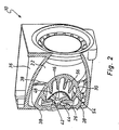
- a wall projection arrangement 54 which is also recognizable in the figures, is provided on an inner side 31.
- This comprises a plurality of wall projections 56, which extend along the housing 22 or the wall portion 30 thereof approximately in the direction of the longitudinal axis L. It can be seen that, in the transition region 28, each of the bottom projections 44 merges into a respective wall projection 56 assigned to it, wherein this transition is preferably formed without interruption. Furthermore, between each two wall projections 56, to which a bottom projection 44 connects, in each case a wall projection 56 'is provided, to which no bottom projection 44 adjoins.
- An essential characteristic of the housing 22 is that, with a comparatively large inner surface contributing to the heat transfer, the flow resistance for the heated gases leaving the flame tube 16 is kept comparatively low, since the various projections which contribute to the increase in the total surface area, in the flow direction which is responsible for the heated gases is predetermined or provided extend. Thereby, the total flow resistance for the heated gases generated in the combustion is kept small, which allows a very efficient operation of the heater.
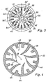
- the Fig. 4 shows a view of a bottom portion 26 of a designed according to the principles of the invention housing 22. It can be seen that the bottom projections 44 are curved from radially outward to radially inward, so that in the region of the radially inner free end portions 46 of which have an extension direction component in the circumferential direction , The heated gas flowing out of the combustion chamber 14 along the flame tube 16, due to the conveying action of an inserted blower, has a twist which is indicated by the arrows in FIG Fig. 4 is indicated.
- the bottom projections 44 By the configuration of the bottom projections 44, which is bent in the opposite direction to this twisting direction, the heated gas to be flowed in the axial direction and with swirl on the bottom region 26 is made easier to enter into the intermediate space formed between each two of the bottom projections 44, thus achieving a reduction of the flow resistance.
- the bottom projections 44 essentially form guide surfaces for the oncoming and deflected gas with their convexly curved surface regions 45.
- the statement that at least a portion of the bottom projections 44 means curved is formed so that they have curved or possibly also angled extending surface areas.
Description
- Die vorliegende Erfindung betrifft eine Heizeinrichtung, insbesondere eine Kraftfahrzeugheizeinrichtung, gemäß dem Oberbegriff des Anspruchs 1.
- Die
DE 196 13 760 A1 offenbart eine Wärmetauscheranordnung für ein Heizgerät, wobei diese Wärmetauscheranordnung topfartig ausgebildet ist und mit ihrem Wandungsbereich eine Brennkammer umgibt. Die aus der Brennkammer austretenden heißen Abgase treffen auf den Bodenbereich, werden dort axial umgelenkt und strömen dann entlang des Wandungsbereichs zum axial offenen Ende des Wärmetauschergehäuses. - Zum Erreichen einer verbesserten Wärmeübertragung zwischen den Verbrennungsabgasen und dem Wärmetauschergehäuse weist dieses im Bodenbereich an der dem Gehäuseinneren zugewandten Seite eine Mehrzahl stiftartiger Vorsprünge auf. Diese stiftartigen Vorsprünge erstrecken sich parallel zur Längsachse des Gehäuses und weisen eine kegelstumpfartige Formgebung auf. Das aus der Brennkammer austretende heiße Gas durchströmt den zwischen den stiftartigen Vorsprüngen gebildeten Raumbereich und trifft dabei auf eine vergleichsweise große Oberfläche.
- Eine Heizeinrichtung ist aus der
DE 38 07 189 A1 bekannt. Bei dieser bekannten Heizeinrichtung sind am Wandungsbereich eines topfartigen Wärmetauschergehäuses in dessen Längsrichtung sich erstreckende Wärmeübertragungsrippen vorgesehen, welche sich entlang der Außenseite eines Flammrohrs erstrecken. Das Flammrohr ist an seinem dem Bodenbereich nahen Ende in Richtung auf den Bodenbereich zu offen. Der Bodenbereich ist im Wesentlichen planar ausgebildet und liegt somit dem offenen Ende des Flammrohrs mit einer ebenen Oberfläche gegenüber. - Die
FR 2 617 579 A - Eine Heizeinrichtung gemäβß dem Oberbegriff des Anspruchs 1 ist aus der
DE 197 34 814 C1 bekannt. - Es ist die Aufgabe der vorliegenden Erfindung, eine gattungsgemäße Heizeinrichtung so weiterzubilden, dass ein Wärmeübertrag mit erhöhter Effizienz erreicht werden kann. Erfindungsgemäß wird diese Aufgabe durch die im Anspruch 1 definierte Heizeinrichtung gelöst.
- Durch die erfindungsgemäße Ausgestaltung einer Heizeinrichtung wird zum einen dafür gesorgt, dass durch Erhöhung der Oberfläche ein gutes Wärmeübertragungsvermögen durch Vergrößerung der Wärmeübertragungsoberfläche bereitgestellt wird. Wesentlich hierfür ist das Vorsehen rippenartiger Vorsprünge am Bodenbereich. Darüber hinaus sorgt die Orientierung dieser rippenartigen Vorsprünge , nämlich in Richtung von der Wandung weg dafür, dass das im Bodenbereich auf das Gehäuse auftreffende und dort im Allgemeinen nach radial außen und dann axial umgelenkte erwärmte Gas beim Strömen entlang einer vergleichsweise großen Oberfläche einen deutlich geringeren Gasströmungswiderstand erfährt, als dies beim Bereitstellen einer Vielzahl stiftartiger Vorsprünge der Fall ist.
- Die Bodenvorsprungsanordnung weist eine Mehrzahl von in sternartiger Konfiguration angeordneten Bodenvorsprüngen auf. Durch die sternartige Konfiguration wird, wie bei bereits ausgeführt, bei vergrößerter Gesamtoberfläche für einen möglichst geringen Strömungswiderstand gesorgt. Dabei kann beispielsweise vorgesehen sein, dass die Bodenvorsprünge sich von einem zentralen Bereich des Bodenbereichs in Richtung zum Wandungsbereich erstrecken. Um das Umströmen der rippenartigen Vorsprünge so wenig als möglich zu behindern, wird vorgeschlagen, dass die Bodenvorsprünge in ihren einander näher liegenden Endbereichen nicht miteinander in Verbindung stehen.
- Gemäß der vorliegenden Erfindung ist ferner vorgesehen, dass die Bodenvorsprünge gekrümmt ausgebildet sind, und zwar entgegengesetzt der Drallrichtung eines auf den Bodenbereich zuströmenden Verbrennungsabgasstroms. Durch die gekrümmte Ausgestaltung ermöglichen die Bodenvorsprünge einen besseren Eintritt des heranströmenden Fluids bzw. des heranströmenden Gases in den Zwischenraum zwischen den einzelnen Bodenvorsprüngen und vermindern somit den Strömungswiderstand.
- Gemäß einem weiteren Aspekt der vorliegenden Erfindung kann vorgesehen sein, dass an dem Wandungsbereich an einer dem Gehäuseinneren zugewandten Seite eine Wandungsvorsprungsanordnung vorgesehen ist, umfassend wenigstens einem Bodenvorsprung der Bodenvorsprungsanordnung zugeordnet einen an diesen anschließenden und sich in Richtung vom Bodenbereich weg erstreckenden Wandungsvorsprung. Auch beim Strömen entlang des Wandungsbereichs wird für das erwärmte Gas somit eine vergrößerte Oberfläche bereitgestellt. Durch das Anschließen an einen bereits im Bodenbereich vorgesehenen Bodenvorsprung kann der Strömungswiderstand weiter vermindert werden. Hierzu kann weiter vorzugsweise vorgesehen sein, dass in einem Übergangsbereich zwischen dem Bodenbereich und dem Wandungsbereich wenigstens ein Bodenvorsprung im Wesentlichen unterbrechungsfrei in einen Wandungsvorsprung übergeht.
- Insbesondere dann, wenn eine sternartige Konfiguration der Bodenvorsprünge bereitgestellt ist, ergibt sich eine Anordnung, bei welcher im radial äußeren Bereich - bezogen auf das Zentrum der sternenartigen Konfiguration - ein größerer Umfangsabstand der Bodenvorsprünge vorhanden ist, als im radial inneren Bereich. Um dennoch im Wandungsbereich die zum Wärmeübertrag genutzte Oberfläche so groß als möglich gestalten zu können, wird vorgeschlagen, dass die Wandungsvorsprungsanordnung wenigstens einen Wandungsvorsprung aufweist, an welchen kein Bodenvorsprung anschließt. Ein derartiger Wandungsvorsprung kann dann beispielsweise im Bereich zwischen zwei Wandungsvorsprüngen vorgesehen sein, die an einen jeweils zugeordneten Bodenvorsprung anschließen.
- Der oder die Wandungsvorsprünge können derart ausgebildet sein, dass sie sich näherungsweise in Richtung einer Längsmittelachse des Gehäuses erstrecken.
- Im Folgenden wird die Erfindung mit Bezug auf die beiliegenden Zeichnungen detailliert beschrieben. Es zeigt:
- Fig. 1
- eine Längsschnittansicht einer Heizeinrichtung, welche eine Wärmetauscheranordnung aufweist;
- Fig. 2
- eine perspektivische Ansicht einer Heizeinrichtung, teilweise im Schnitt dargestellt;
- Fig. 3
- eine Axialansicht eines Wärmetauschergehäuses;
- Fig. 4
- eine Querschnittansicht eines erfindungsgemäß aufgebauten Wärmetauschergehäuses nahe dem Bodenbereich desselben.
- In
Fig. 1 ist eine Ansicht der wesentlichen Komponenten einer allgemein mit 10 bezeichneten Heizeinrichtung dargestellt, wie sie beispielsweise als Standheizung oder Zuheizer in einem Kraftfahrzeug Anwendung finden kann. Die Heizeinrichtung 10 umfasst eine allgemein mit 12 bezeichnete Brennkammer, aus welcher über eine Flammblende 14 die bei der Verbrennung entstehenden erhitzten Gase in den von einem Flammrohr 16 umschlossenen, sich entlang einer Längsachse L erstreckenden Raumbereich 18 eintreten. Das Flammrohr 16 ist an seinem von der Brennkammer 12 entfernt gelegenen Endbereich 20 axial offen. - Ein im Wesentlichen topfartig ausgebildetes Gehäuse 22 einer Wärmetauscheranordnung 24 umgibt das Flammrohr 16 radial außen und liegt mit seinem Bodenbereich 26 dem axial offenen Endbereich 20 des Flammrohrs 16 gegenüber. Ein an den Bodenbereich 26 in einem Verbindungsbereich 28 anschließender Wandungsbereich 30 des Gehäuses 22 erstreckt sich näherungsweise parallel zum Flammrohr 16 und näherungsweise auch entlang der Längsachse L, welche gleichzeitig auch eine Längsmittellinie für das Flammrohr 16 und das Gehäuse 22 bildet. Zwischen dem Flammrohr 16 und dem Wandungsbereich 30 des Gehäuses 22 ist ein näherungsweise ringartiger Raumbereich 32 gebildet. Die aus dem axial offenen Endbereich 20 des Flammrohrs 16 ausgetretenen erwärmten Gase treffen auf den Bodenbereich 26 auf und werden dort, wie in
Fig. 1 durch Pfeile dargestellt, zunächst nach radial außen und dann in Achsrichtung umgelenkt, so dass sie entlang des Flammrohrs 16 und des Wandungsbereichs 30 wieder in Richtung auf die Brennkammer 14 zu und radial außerhalb davon nach außen abgegeben werden. - Ferner sei noch darauf hingewiesen, dass zum Bilden eines von beispielsweise zu erwärmendem Wasser zu durchströmenden Hohlraums 34 das Gehäuse 22 der Wärmetauscheranordnung 24 an seiner Außenseite durch ein allgemein als Wassermantel bezeichnetes weiteres Gehäuse 36 umgeben ist. Um hier eine bestimmte Strömungsrichtung für die zu erwärmende Flüssigkeit vorzugeben, sind an der Außenseite des Gehäuses 22 mehrere rippenartige Erhöhungen 38 vorgesehen, welche dafür sorgen, dass die zu erwärmende Flüssigkeit in möglichst guten Wärmeübertragunsgkontakt mit dem Gehäuse 22 treten kann.
- Wie man auch in den
Figuren 2 und3 erkennt, weist das Gehäuse 22 an seinem Bodenbereich 26 an der zum Gehäuseinneren, also auch zum Flammrohr 16 hin weisenden Seite 40 eine allgemein mit 42 bezeichnete Bodenvorsprungsanordnung auf. Diese umfasst eine Mehrzahl von bezüglich der Längsachse L sich näherungsweise radial erstreckenden Bodenvorsprüngen 44. In ihrem radial inneren Bereich 46 enden die Bodenvorsprünge 44 nahe dem zentralen Bereich 48 des Bodenbereichs 26, stehen dort jedoch nicht in gegenseitiger Verbindung. Es wird somit nahe dem zentralen Bereich 48 ein von den Endbereichen 46 im Wesentlichen umschlossener Raumbereich 50 gebildet, in welchen die im zentralen Bereich des Flammrohrs 16 strömenden Gase eintreten können. Bei der Umlenkung nach radial außen treten diese Gase dann durch die Zwischenräume 52 zwischen zwei Bodenvorsprüngen 44 hindurch nach radial außen und es wird auf diese Art und Weise dafür gesorgt, dass am Bodenbereich 16 keine gegen Umströmung abgeschirmten oder blockierten Raum- oder Volumenbereiche entstehen. - Am Wandungsbereich 30 des Gehäuses 22 ist an einer Innenseite 31 eine in den Figuren auch erkennbare Wandungsvorsprungsanordnung 54 vorgesehen. Diese umfasst eine Mehrzahl von Wandungsvorsprüngen 56, welche sich entlang des Gehäuses 22 bzw. des Wandungsbereichs 30 desselben näherungsweise in der Richtung der Längsachse L erstrecken. Man erkennt, dass im Übergangsbereich 28 jeder der Bodenvorsprünge 44 in einen jeweils diesem zugeordneten Wandungsvorsprung 56 übergeht, wobei dieser Übergang vorzugsweise unterbrechungsfrei ausgebildet ist. Ferner ist zwischen jeweils zwei Wandungsvorsprüngen 56, an die ein Bodenvorsprung 44 anschließt, jeweils ein Wandungsvorsprung 56' vorgesehen, an den kein Bodenvorsprung 44 anschließt. Man erkennt vor allem in der Draufsicht der
Fig. 3 , dass durch die sternartige Konfiguration der Bodenvorsprünge 44 diese im radial äußeren Bereich einen derartigen gegenseitigen Umfangsabstand aufweisen, dass ein weiterer Wandungsvorsprung 56' Platz findet. Es kann auf diese Art und Weise die gesamt zur Wärmeübertragung beitragende Oberfläche des Gehäuses 22 an der Innenseite desselben noch weiter vergrößert werden. - Ein wesentliches Charakteristikum des Gehäuses 22 ist, dass bei vergleichsweise großer zur Wärmeübertragung beitragender Innenoberfläche der Strömungswiderstand für die das Flammrohr 16 verlassenden erwärmten Gase vergleichsweise gering gehalten ist, da die verschiedenen Vorsprünge, welche zur Erhöhung der Gesamtoberfläche beitragen, sich in der Strömungsrichtung, welche für die erwärmten Gase vorgegeben oder vorgesehen ist, erstrecken. Dadurch wird der Gesamtströmungswiderstand für die bei der Verbrennung erzeugten erwärmten Gase klein gehalten, was einen sehr effizienten Betrieb der Heizeinrichtung gestattet.
- Die
Fig. 4 zeigt eine Ansicht eines Bodenbereichs 26 eines gemäß den Prinzipien der Erfindung ausgestalteten Gehäuses 22. Man erkennt hier, dass die Bodenvorsprünge 44 von radial außen nach radial innen gekrümmt sind, so dass im Bereich der radial inneren freien Endbereiche 46 derselben diese eine Erstreckungsrichtungskomponente in Umfangsrichtung aufweisen. Das aus der Brennkammer 14 entlang des Flammrohrs 16 strömende erwärmte Gas weist auf Grund der Förderwirkung eines eingesetzten Gebläses einen Drall auf, welcher durch die Pfeile inFig. 4 angedeutet ist. Durch die entgegengesetzt dieser Drallrichtung abgekrümmte Konfiguration der Bodenvorsprünge 44 wird dem in Achsrichtung und mit Drall auf den Bodenbereich 26 zu strömenden erwärmten Gas ein leichterer Eintritt in den zwischen jeweils zwei der Bodenvorsprünge 44 gebildeten Zwischenraum ermöglicht und somit eine Verminderung des Strömungswiderstands erreicht. Dabei bilden also die Bodenvorsprünge 44 im Wesentlichen mit ihren konvex gekrümmten Oberflächenbereichen 45 Leitflächen für das heranströmende und umgelenkte Gas. Im Sinne der vorliegenden Erfindung bedeutet also die Aussage, dass zumindest ein Teil der Bodenvorsprünge 44 gekrümmt ausgebildet ist, dass diese derart gekrümmt bzw. ggf. auch abgewinkelt verlaufende Oberflächenbereiche aufweisen.
Claims (7)
- Heizeinrichtung, insbesondere für ein Kraftfahrzeug, umfassend eine Wärmetauscheranordnung (24), diese umfassend ein topfartiges Gehäuse (22) mit einem Bodenbereich (26) und einem Wandungsbereich (30), wobei die Heizeinrichtung ferner eine Brennkammer (12) und ein. Verbrennungsabgase von der Brennkammer (12) in Richtung auf den Bodenbereich (26) zu führendes Flammrohr (16) umfasst, das an seinem dem Bodenbereich (26) gegenüber liegenden Ende in Richtung zum Bodenbereich (26) axial offen ist, und wobei zwischen dem Flammrohr (16) und dem Wandungsbereich (30) ein am Bodenbereich (26) umgelenkte Verbrennungsabgase in Richtung zur Brennkammer (12) zurückführender, ringartiger Raumbereich gebildet ist, wobei an einer dem Gehäuseinneren zugewandten Seite (40) des Bodenbereichs (26) eine Bodenvorsprungsanordnung (42) vorgesehen ist, wobei die Bodenvorsprungsanordnung (42) eine Mehrzahl von sich in Richtung von dem Wandungsbereich (30) weg erstreckenden, in stemartiger Konfiguration angeordneten rippenartigen Bodenvorsprüngen (44) aufweist, dadurch gekennzeichnet, dass die Bodenvorsprünge entgegengesetzt der Drallrichtung eines auf den Bodenbereich (26) zuströmenden Verbrennungsabgasstroms von radial außen nach radial innen gekrümmt ausgebildet sind.
- Heizeinrichtung nach Anspruch 1,
dadurch gekennzeichnet, dass die Bodenvorsprünge (44) sich von einem zentralen Bereich (48) des Bodenbereichs (26) in Richtung zum Wandungsbereich (30) erstrecken. - Heizeinrichtung nach Anspruch 1 oder 2,
dadurch gekennzeichnet, dass die Bodenvorsprünge (44) in ihren einander näher liegenden Endbereichen (46) nicht miteinander in Verbindung stehen. - Heizeinrichtung nach einem der Ansprüche 1 bis 3,
dadurch gekennzeichnet, dass an dem Wandungsbereich (30) an einer dem Gehäuseinneren zugewandten Seite (31) eine Wandungsvorsprungsanordnung (54) vorgesehen ist, umfassend wenigstens einem Bodenvorsprung (44) der Bodenvorsprungsanordnung (42) zugeordnet einen an diesen anschließenden und sich in Richtung vom Bodenbereich (26) weg erstreckenden Wandungsvorsprung (56). - Heizeinrichtung nach Anspruch 4,
dadurch gekennzeichnet, dass in einem Übergangsbereich (28) zwischen dem Bodenbereich (26) und dem Wandungsbereich (30) wenigstens ein Bodenvorsprung (44) im Wesentlichen unterbrechungsfrei in einen Wandungsvorsprung (56) übergeht. - Heizeinrichtung nach Anspruch 4 oder 5,
dadurch gekennzeichnet, dass die Wandungsvorsprungsanordnung (54) wenigstens einen Wandungsvorsprung (56') aufweist, an welchen kein Bodenvorsprung (44) anschließt. - Heizeinrichtung nach einem der Ansprüche 4 bis 6,
dadurch gekennzeichnet, dass der wenigstens eine Wandungsvorsprung (56) sich näherungsweise in Richtung einer Längsmittelachse (L) des Gehäuses (22) erstreckt.
Applications Claiming Priority (2)
| Application Number | Priority Date | Filing Date | Title |
|---|---|---|---|
| DE10146610 | 2001-09-21 | ||
| DE2001146610 DE10146610A1 (de) | 2001-09-21 | 2001-09-21 | Wärmetauscheranordnung für eine Heizeinrichtung, insbesondere eine Kraftfahrzeugheizung |
Publications (3)
| Publication Number | Publication Date |
|---|---|
| EP1296101A2 EP1296101A2 (de) | 2003-03-26 |
| EP1296101A3 EP1296101A3 (de) | 2003-12-10 |
| EP1296101B1 true EP1296101B1 (de) | 2012-06-20 |
Family
ID=7699827
Family Applications (1)
| Application Number | Title | Priority Date | Filing Date |
|---|---|---|---|
| EP02015117A Expired - Fee Related EP1296101B1 (de) | 2001-09-21 | 2002-07-05 | Heizeinrichtung, insbesondere eine Kraftfahrzeugheizeinrichtung |
Country Status (2)
| Country | Link |
|---|---|
| EP (1) | EP1296101B1 (de) |
| DE (1) | DE10146610A1 (de) |
Families Citing this family (7)
| Publication number | Priority date | Publication date | Assignee | Title |
|---|---|---|---|---|
| DE102004019870A1 (de) * | 2004-04-23 | 2005-11-17 | J. Eberspächer GmbH & Co. KG | Heizgerät, insbesondere für ein Fahrzeug |
| DE102005053514A1 (de) | 2004-11-26 | 2006-07-06 | Webasto Ag | Luftheizgerät für ein Kraftfahrzeug |
| DE102008025314B4 (de) | 2008-05-27 | 2021-10-07 | Eberspächer Climate Control Systems GmbH | Wärmetauscheranordnung für eine Heizeinrichtung, insbesondere für ein Fahrzeug |
| DE102008034139B4 (de) | 2008-07-22 | 2022-11-10 | Eberspächer Climate Control Systems GmbH | Heizgerät, insbesondere für ein Fahrzeug |
| DE102011004159A1 (de) * | 2011-02-15 | 2012-08-16 | J. Eberspächer GmbH & Co. KG | Wärmetauscheranordnung, insbesondere für ein brennstoffbetriebenes Fahrzeugheizgerät |
| DE102014010891A1 (de) * | 2014-07-23 | 2016-01-28 | Webasto SE | Wärmeübertrager und Baukastensystem zur Herstellung eines Wärmeübertragers |
| DE102017100133A1 (de) * | 2017-01-05 | 2018-07-05 | Eberspächer Climate Control Systems GmbH & Co. KG | Wärmetauschergehäuse |
Citations (2)
| Publication number | Priority date | Publication date | Assignee | Title |
|---|---|---|---|---|
| US2744516A (en) * | 1951-10-13 | 1956-05-08 | American Air Filter Co | Portable fluid fuel burning air heater |
| DE19734814C1 (de) * | 1997-08-12 | 1999-01-14 | Webasto Thermosysteme Gmbh | Brennstoffbetriebene Heizvorrichtung mit optimierter Verbrennungsgasführung |
Family Cites Families (3)
| Publication number | Priority date | Publication date | Assignee | Title |
|---|---|---|---|---|
| FR2617579B1 (fr) * | 1987-07-03 | 1989-12-08 | Airelec Ind | Chaudiere de chauffage central pour bruleur a air souffle, comprenant un foyer sec et une resistance chauffante |
| DE3807189A1 (de) * | 1988-03-04 | 1989-09-14 | Webasto Ag Fahrzeugtechnik | Heizgeraet, insbesondere fahrzeugzusatzheizgeraet |
| DE19613760A1 (de) | 1996-04-06 | 1997-10-09 | Webasto Thermosysteme Gmbh | Wärmetauscher für ein Heizgerät |
-
2001
- 2001-09-21 DE DE2001146610 patent/DE10146610A1/de not_active Ceased
-
2002
- 2002-07-05 EP EP02015117A patent/EP1296101B1/de not_active Expired - Fee Related
Patent Citations (2)
| Publication number | Priority date | Publication date | Assignee | Title |
|---|---|---|---|---|
| US2744516A (en) * | 1951-10-13 | 1956-05-08 | American Air Filter Co | Portable fluid fuel burning air heater |
| DE19734814C1 (de) * | 1997-08-12 | 1999-01-14 | Webasto Thermosysteme Gmbh | Brennstoffbetriebene Heizvorrichtung mit optimierter Verbrennungsgasführung |
Also Published As
| Publication number | Publication date |
|---|---|
| DE10146610A1 (de) | 2003-04-24 |
| EP1296101A3 (de) | 2003-12-10 |
| EP1296101A2 (de) | 2003-03-26 |
Similar Documents
| Publication | Publication Date | Title |
|---|---|---|
| EP3040638B1 (de) | Wärmeübertragerrohr und heizkessel mit einem solchen wärmeübertragerrohr | |
| EP2546573B1 (de) | Fahrzeugheizgerät | |
| DE60015374T2 (de) | Spiralwärmetauscher | |
| EP0544853B1 (de) | Luftheizgerät | |
| EP0175875B1 (de) | Öl- oder Gasbrenner zur Heissgaserzeugung | |
| DE10143458B4 (de) | Zusatzheizgerät mit einem Wärmeübertrager | |
| EP1296101B1 (de) | Heizeinrichtung, insbesondere eine Kraftfahrzeugheizeinrichtung | |
| DE19734814C1 (de) | Brennstoffbetriebene Heizvorrichtung mit optimierter Verbrennungsgasführung | |
| EP1681519A2 (de) | Wärmetauscherkörper und Fahrzeugheizgerät mit einem Wärmetauscherkörper | |
| EP2096372A2 (de) | Heizgerät | |
| WO2007079730A1 (de) | Heizkessel | |
| EP1445552B1 (de) | Fahrzeugheizeinrichtung | |
| EP2157382A2 (de) | Heizgerät | |
| DE102014214768A1 (de) | Wärmetauscheranordnung, insbesondere für ein Fahrzeugheizgerät | |
| DE2107514A1 (de) | Vorrichtung zum Heizen mit Infrarot Strahlung | |
| DE102004008358B4 (de) | Fahrzeugheizgerät | |
| DE3320903C2 (de) | ||
| DE19926264B4 (de) | Heizgerät | |
| DE102011081401B4 (de) | Wärmetauscheranordnung, insbesondere für ein brennstoffbetriebenes Fahrzeugheizgerät | |
| EP2306112B1 (de) | Heizgerät | |
| EP0971194B1 (de) | Stehender Wärmetauscher | |
| DE10262065B4 (de) | Zusatzheizgerät mit einem Wärmeübertrager | |
| DE1501777B2 (de) | Verbrennungskammer für Heizvorrichtungen insbesondere für Lufterhitzer | |
| DE102008025314B4 (de) | Wärmetauscheranordnung für eine Heizeinrichtung, insbesondere für ein Fahrzeug | |
| DE10014104B4 (de) | Brenner |
Legal Events
| Date | Code | Title | Description |
|---|---|---|---|
| PUAI | Public reference made under article 153(3) epc to a published international application that has entered the european phase |
Free format text: ORIGINAL CODE: 0009012 |
|
| AK | Designated contracting states |
Designated state(s): AT BE BG CH CY CZ DE DK EE ES FI FR GB GR IE IT LI LU MC NL PT SE SK TR Kind code of ref document: A2 Designated state(s): AT BE BG CH CY CZ DE DK EE ES FI FR GB GR IE IT LI LU MC NL PT SE SK TR |
|
| AX | Request for extension of the european patent |
Extension state: AL LT LV MK RO SI |
|
| PUAL | Search report despatched |
Free format text: ORIGINAL CODE: 0009013 |
|
| AK | Designated contracting states |
Kind code of ref document: A3 Designated state(s): AT BE BG CH CY CZ DE DK EE ES FI FR GB GR IE IT LI LU MC NL PT SE SK TR |
|
| AX | Request for extension of the european patent |
Extension state: AL LT LV MK RO SI |
|
| RIC1 | Information provided on ipc code assigned before grant |
Ipc: 7F 24H 9/00 B Ipc: 7F 24H 1/26 A |
|
| 17P | Request for examination filed |
Effective date: 20040212 |
|
| AKX | Designation fees paid |
Designated state(s): CZ DE |
|
| 17Q | First examination report despatched |
Effective date: 20051017 |
|
| RTI1 | Title (correction) |
Free format text: HEATER, ESPECIALLY FOR A VEHICLE HEATER |
|
| GRAP | Despatch of communication of intention to grant a patent |
Free format text: ORIGINAL CODE: EPIDOSNIGR1 |
|
| GRAS | Grant fee paid |
Free format text: ORIGINAL CODE: EPIDOSNIGR3 |
|
| GRAA | (expected) grant |
Free format text: ORIGINAL CODE: 0009210 |
|
| AK | Designated contracting states |
Kind code of ref document: B1 Designated state(s): CZ DE |
|
| REG | Reference to a national code |
Ref country code: DE Ref legal event code: R096 Ref document number: 50215512 Country of ref document: DE Effective date: 20120816 |
|
| REG | Reference to a national code |
Ref country code: DE Ref legal event code: R097 Ref document number: 50215512 Country of ref document: DE |
|
| PLBE | No opposition filed within time limit |
Free format text: ORIGINAL CODE: 0009261 |
|
| STAA | Information on the status of an ep patent application or granted ep patent |
Free format text: STATUS: NO OPPOSITION FILED WITHIN TIME LIMIT |
|
| 26N | No opposition filed |
Effective date: 20130321 |
|
| REG | Reference to a national code |
Ref country code: DE Ref legal event code: R082 Ref document number: 50215512 Country of ref document: DE Representative=s name: WEICKMANN & WEICKMANN, DE |
|
| REG | Reference to a national code |
Ref country code: DE Ref legal event code: R097 Ref document number: 50215512 Country of ref document: DE Effective date: 20130321 |
|
| REG | Reference to a national code |
Ref country code: DE Ref legal event code: R081 Ref document number: 50215512 Country of ref document: DE Owner name: EBERSPAECHER CLIMATE CONTROL SYSTEMS GMBH & CO, DE Free format text: FORMER OWNER: J. EBERSPAECHER GMBH & CO. KG, 73730 ESSLINGEN, DE Effective date: 20130607 Ref country code: DE Ref legal event code: R081 Ref document number: 50215512 Country of ref document: DE Owner name: EBERSPAECHER CLIMATE CONTROL SYSTEMS GMBH & CO, DE Free format text: FORMER OWNER: J. EBERSPAECHER GMBH & CO. KG, 73730 ESSLINGEN, DE Effective date: 20120621 Ref country code: DE Ref legal event code: R082 Ref document number: 50215512 Country of ref document: DE Representative=s name: WEICKMANN & WEICKMANN, DE Effective date: 20130607 Ref country code: DE Ref legal event code: R082 Ref document number: 50215512 Country of ref document: DE Representative=s name: PATENTANWAELTE WEICKMANN & WEICKMANN, DE Effective date: 20130607 Ref country code: DE Ref legal event code: R082 Ref document number: 50215512 Country of ref document: DE Representative=s name: RUTTENSPERGER LACHNIT TROSSIN GOMOLL PATENT- U, DE Effective date: 20130607 Ref country code: DE Ref legal event code: R082 Ref document number: 50215512 Country of ref document: DE Representative=s name: RUTTENSPERGER LACHNIT TROSSIN GOMOLL, PATENT- , DE Effective date: 20130607 |
|
| PGFP | Annual fee paid to national office [announced via postgrant information from national office to epo] |
Ref country code: CZ Payment date: 20140624 Year of fee payment: 13 |
|
| REG | Reference to a national code |
Ref country code: DE Ref legal event code: R082 Ref document number: 50215512 Country of ref document: DE Representative=s name: RUTTENSPERGER LACHNIT TROSSIN GOMOLL PATENT- U, DE Ref country code: DE Ref legal event code: R082 Ref document number: 50215512 Country of ref document: DE Representative=s name: RUTTENSPERGER LACHNIT TROSSIN GOMOLL, PATENT- , DE |
|
| PGFP | Annual fee paid to national office [announced via postgrant information from national office to epo] |
Ref country code: DE Payment date: 20150731 Year of fee payment: 14 |
|
| PG25 | Lapsed in a contracting state [announced via postgrant information from national office to epo] |
Ref country code: CZ Free format text: LAPSE BECAUSE OF NON-PAYMENT OF DUE FEES Effective date: 20150705 |
|
| REG | Reference to a national code |
Ref country code: DE Ref legal event code: R119 Ref document number: 50215512 Country of ref document: DE |
|
| PG25 | Lapsed in a contracting state [announced via postgrant information from national office to epo] |
Ref country code: DE Free format text: LAPSE BECAUSE OF NON-PAYMENT OF DUE FEES Effective date: 20170201 |