EP1296003A1 - Falzkehle für bogenförmige Kehlen und Verfahren zur Herstellung von Falzkehlen - Google Patents
Falzkehle für bogenförmige Kehlen und Verfahren zur Herstellung von Falzkehlen Download PDFInfo
- Publication number
- EP1296003A1 EP1296003A1 EP02021096A EP02021096A EP1296003A1 EP 1296003 A1 EP1296003 A1 EP 1296003A1 EP 02021096 A EP02021096 A EP 02021096A EP 02021096 A EP02021096 A EP 02021096A EP 1296003 A1 EP1296003 A1 EP 1296003A1
- Authority
- EP
- European Patent Office
- Prior art keywords
- fillet
- elements
- fold
- throat
- groove according
- Prior art date
- Legal status (The legal status is an assumption and is not a legal conclusion. Google has not performed a legal analysis and makes no representation as to the accuracy of the status listed.)
- Withdrawn
Links
Images


Classifications
-
- E—FIXED CONSTRUCTIONS
- E04—BUILDING
- E04D—ROOF COVERINGS; SKY-LIGHTS; GUTTERS; ROOF-WORKING TOOLS
- E04D13/00—Special arrangements or devices in connection with roof coverings; Protection against birds; Roof drainage ; Sky-lights
- E04D13/14—Junctions of roof sheathings to chimneys or other parts extending above the roof
- E04D13/147—Junctions of roof sheathings to chimneys or other parts extending above the roof specially adapted for inclined roofs
- E04D13/1473—Junctions of roof sheathings to chimneys or other parts extending above the roof specially adapted for inclined roofs specially adapted to the cross-section of the parts extending above the roof
- E04D13/1476—Junctions of roof sheathings to chimneys or other parts extending above the roof specially adapted for inclined roofs specially adapted to the cross-section of the parts extending above the roof wherein the parts extending above the roof have a generally circular cross-section
-
- E—FIXED CONSTRUCTIONS
- E04—BUILDING
- E04D—ROOF COVERINGS; SKY-LIGHTS; GUTTERS; ROOF-WORKING TOOLS
- E04D1/00—Roof covering by making use of tiles, slates, shingles, or other small roofing elements
- E04D1/30—Special roof-covering elements, e.g. ridge tiles, gutter tiles, gable tiles, ventilation tiles
-
- E—FIXED CONSTRUCTIONS
- E04—BUILDING
- E04D—ROOF COVERINGS; SKY-LIGHTS; GUTTERS; ROOF-WORKING TOOLS
- E04D1/00—Roof covering by making use of tiles, slates, shingles, or other small roofing elements
- E04D1/30—Special roof-covering elements, e.g. ridge tiles, gutter tiles, gable tiles, ventilation tiles
- E04D2001/301—Special roof-covering elements, e.g. ridge tiles, gutter tiles, gable tiles, ventilation tiles at roof edges, e.g. intersections with walls
- E04D2001/303—Eave tiles
-
- E—FIXED CONSTRUCTIONS
- E04—BUILDING
- E04D—ROOF COVERINGS; SKY-LIGHTS; GUTTERS; ROOF-WORKING TOOLS
- E04D1/00—Roof covering by making use of tiles, slates, shingles, or other small roofing elements
- E04D1/30—Special roof-covering elements, e.g. ridge tiles, gutter tiles, gable tiles, ventilation tiles
- E04D2001/304—Special roof-covering elements, e.g. ridge tiles, gutter tiles, gable tiles, ventilation tiles at roof intersections, e.g. valley tiles, ridge tiles
Definitions
- the invention relates to a fold groove with an arched fold, for example on dormer windows or arched roof connections and a method for their Production.
- Throat linings for arched throats on dormer windows or roof connections are known. They are always required when an arcuate Gaupe penetrates the main roof. There are different forms such throats known.
- In addition to an arcuate training in terms of Gaupe can be concave or convex shapes of the roof and / or the Act Gaupe. This is especially true when renovating old or historic buildings Buildings.
- Throat lining is usually done with sheet metal. These are copper, aluminum or galvanized sheet steel.
- the liner requires the arcuate Folded grooves with sheet metal, sometimes very complicated developments. ever the more the dome shape deviates from the circular arc, the more complex it becomes Preparatory work for cuts. So far it has been the norm Throats to be made using locally adapted sheet metal parts. This usually happens made a template and then cut the sheet into different parts. These parts, which are usually made in very short sections, must then be connected to each other. There are various connection technologies like welding. Soldering, folding using sealing tape known. The waste of sheet metal is in this type of training Throats very high the manual effort to manufacture also, in particular the work on site is very time consuming and therefore costly.
- a method for producing such a throat lining is also known, in which the lining is produced from a single continuous sheet metal strip. Wrinkles are arranged at selected intervals to adapt to the shape of the throat.
- a template is first made on site, for example as a paper strip.
- the folds of the sheet metal strip are then edged according to the template at preselected intervals, the folds having a different width in order to be able to follow the shape of the throat.
- the resulting folded sheet metal strip requires the following work steps before it can be inserted into the throat on the roof. These are pre-upsetting the folds of the sheet metal strip with the fin of a folding hammer and leading edges of the fillet line using folding pliers.
- the fillet sheet is inserted and the throat shape is adjusted, the folds are shaped, the water rebate is edged, any protective film is removed and the adhesive (attachment points) is set.
- the expenditure for this type of execution of such a fold groove is very high. High expenditure of time due to the production of a template and the preparatory work for the production of the sheet metal strip, in addition a further high expenditure of time when adapting the strip in the throat. This type of design requires patience and manual skill in order to obtain an arch groove that meets aesthetic requirements.
- a fillet for arched throats in particular on Dormer windows or roof connections, provided by a System of mountable fillet elements.
- the system enables one high prefabrication costs in the workshop of a roof plumber, on the construction site, however not on the roof, whereby individual adjustments are also possible are.
- the system is also particularly suitable for industrial prefabrication in modern prefabrication plants. It consists of different parts, which can be fitted to the throat in just a few steps and closes tightly are attachable.
- the system can be used so universally that the most varied Throat forms can be realized with it.
- the system of the ready for assembly Fillet elements of a throat from initial fillet element, middle fillet elements, End fillet and fasteners.
- the initial throat element starting at the eaves, then any number follows many middle-throat elements and then the end-throat element, which is the transition to the roof surface on the ridge side.
- the fillet elements are designed so that they can be inserted into one another, but can be rotated with respect to one another within a certain radius executed so that the system follow every change of direction of the throat can.
- fillet elements are made of the use on suitable material on roofs, especially galvanized sheet steel, Aluminum sheet, anodized aluminum sheet, color-treated metallic Sheets, copper sheet, from mineral building materials, such as mineral fiber boards, e.g. Eternit®, and / or are formed from plastic materials.
- suitable material on roofs especially galvanized sheet steel, Aluminum sheet, anodized aluminum sheet, color-treated metallic Sheets, copper sheet, from mineral building materials, such as mineral fiber boards, e.g. Eternit®, and / or are formed from plastic materials.
- the fillet elements have folds for connection to one another, by means of of which they can be detachably inserted into one another.
- a rebate that has fillet elements is particularly advantageous which arcuate folds are formed with corresponding radii are.
- One embodiment of the solution according to the invention is characterized in that that the fillet elements preferably have a width covering the fillet area 500 mm, and have a height, preferably 450 mm.
- folds are also in the edge areas of the Fillet elements formed.
- the folds the fillet elements have a width of 10 to 40 mm, preferably 20 to 30 mm, own, but are at least designed such that, on the one hand, one is sufficient secure connection is created and on the other hand the penetration of moisture is prevented.
- the folds of the fillet elements should be in accordance with a development of the invention have a height equal to the thickness of the material plus a tolerance for the interlocking of the folds and a seal that may need to be inserted equivalent.
- the initial fillet and the middle fillet element has an upper radius (R1) for the fold on the upper radius
- the middle fillet and the end fillet have a lower radius (R2) for the fold of the lower radius
- the centers of the radii (R1, R2) are spaced apart from one another on the central axis (x). This is ensures that the shape of the throat can be followed as desired. So it is possible, for example, with only five central fillet elements connected to one Start throat element and an end throat element to follow a throat forms a right angle with a radius of 35 cm.
- a further development of the rebate groove according to the invention is characterized in that on the middle-throat elements and the end-throat element about in the right Angle from the central axis (x) in an imaginary line, which is the center of the radius (R2) cuts, the lower fold ends on both sides, the aforementioned fillet element have a width (B1) at this point, from there approximately at right angles run out to the width (B) and then parallel to the central axis up to to the points (b1, b4), the upper Fold ends on both sides at a point that is approximately perpendicular to the central axis (x) and an imaginary one that intersects the center of the radius (R1) Line is formed, then parallel to the central axis up to the points (b2, b3).
- start, middle and fillet elements are designed in such a way that the rows of vertically and horizontally offset elements when merging the elements arise.
- This embodiment is also based on the basic idea of the invention.
- the first row is executed with the start throat element.
- This element forms the first row, for example, on the eaves side. It is made using a push plate attached to the eaves.
- the production of the Fold groove as in the manner already described in the above exemplary embodiments takes place by the middle groove elements with their lower fold in the corresponding upper fold of the initial fillet element become.
- the middle fold elements are in addition to the lower fold with two laterally arranged arcuate folds provided in this embodiment form the upper fold of the middle fillet element, and into which each next row of middle fillet elements of the same embodiment are used becomes.
- These side arch folds are the same Radius, like the lower fold of the middle fillet element.
- This kind of Execution can be a fold groove with horizontal and vertical by 50 Shift percent to create particularly aesthetic fillets.
- approx. 6 cm fold is worked out a little stronger, to bridge the material thicknesses and the bending radii of the metal and to taper the air gap between the sheets.
- a water fold can be folded in order to accrue Water to block the way behind the sheet.
- the object of the invention is also achieved by a method for the production of folds, in particular arcuate folds, that are characterized by the Use of an assembly-ready, in particular prefabricated system from Fillet elements and fasteners according to one or more of the preceding Features of the rebate groove according to the invention.
- Figure 1 shows an initial fillet element 1 as a plan view.
- B denotes the width of the element and H the height.
- the axis is designated by the reference symbol x.
- the intersection point for the radius R1 is indicated on the x axis.
- Figure 1 is a template of the starting element 1 to understand.
- the fold is on the line labeled 6 in Obtained in the usual way by folding.
- the fold will appear at the designated point folded upwards in the installation direction.
- the reference symbols denote b1 to b4 the corner points of the width of the starting element at the in the direction of installation upwards, to the ridge-facing and cut-out side.
- the advantageous embodiment variant of the invention is the height H of the elements 450 mm and the width B 500 mm.
- the radius R1 is in this variant 150 mm.
- the end fillet element 3 is shown in FIG. Identify the same reference numerals the same features that were already presented in Figure 1. On a renewed performance will be avoided.
- H1 Height 1 denotes the axis with an imaginary axis drawn here in broken lines is specified, the axis x at the center of the radius R2 at right angles cuts.
- the radius R2 is 230 mm in one design variant.
- the end fillet 3 With the end fillet 3, the transition of the throat at the junction made on the ridge side.
- the reference numeral 6 is the specified lower fold, which is seen folded down in the device.
- Figures 3 and 4 show the middle fillet element 2. Identify the same reference numerals the same features as in the previously presented figures. you will be therefore not presented again particularly.
- Figure 3 is the Top view of a middle fillet element 2 shown, while in Figure 4 a Processing can be seen.
- the upper fold 5 is cut and fold up and the one below fold 6 by cutting out triangular ones Split and fold down created.
- the folds can be made as already mentioned also make by upsetting or stretching.
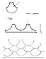
- FIG. 5 shows an embodiment of initial and middle fillet elements, suitable for the execution of an arched groove with staggered rows are.
- This embodiment is also based on the basic idea of the invention.
- the first row is executed with the start throat element.
- This element is designated by the reference numeral 1 in FIG.
- This element forms the First row, for example, on the eaves side. It is attached to the Eaves attached.
- the middle fillet element is also in FIG. 5 with the reference symbol 2 designated. This also makes it clear that the fold groove is made as in the manner already described of the above exemplary embodiments takes place by the middle fillet elements 2 with their lower fold in each corresponding upper fold of the initial fillet element 1 are hung.
- the middle fillet elements 2 are in addition to the lower fold with two on the side arranged arcuate folds provided in this embodiment form the upper fold of the middle fillet element 2, and into which the next one Row of middle fillet elements 2 of the same embodiment is used. This presupposes that these lateral arcuate folds have the same radius have, like the lower fold of the middle fillet.
- This kind of Execution can be a fold groove with horizontal and vertical by 50 Shift percent to create particularly aesthetic fillets. This is shown in the lower part of Figure 5. In the middle of the arch fold at the bottom In part, about 6 cm of fold are worked out a little more to the material thickness Approx.
Landscapes
- Engineering & Computer Science (AREA)
- Architecture (AREA)
- Civil Engineering (AREA)
- Structural Engineering (AREA)
- Roof Covering Using Slabs Or Stiff Sheets (AREA)
Abstract
Description
Dann erfolgt das Einlegen des Kehlbleches und Anpassen des Kehlverlaufes, das Ausformen der Falten, Aufkanten des Wasserfalzes, Entfernen eventuell vorhandener Schutzfolie und setzen der Hafte (Befestigungspunkte). Wie die Beschreibung des so durchzuführenden Verfahrens zeigt, ist der Aufwand für diese Art der Ausführung einer solchen Faltenkehle sehr hoch. Hoher Zeitaufwand bedingt durch das Anfertigen einer Schablone sowie der Vorbereitungsarbeiten zur Anfertigung des Blechstreifens, zusätzlich weiterer hoher Zeitaufwand bei der Anpassung des Streifens in der Kehle. Diese Art der Ausführung erfordert insbesondere Geduld und handwerkliches Geschick, um auch eine ästhetischen Anforderungen genügende Bogenkehle zu erhalten.
- Anfertigen der Anfangskehlelemente (1), Mittelkehlelemente (2), und Endkehlelemente (3) in einer Vorfertigungsstätte,
- Montieren der Kehlelemente (1, 2, 3) beginnend mit dem Anfangskehlelement (1) an der Traufe, indem dieses Element am traufseitigen Beginn der Kehle mittels bekannter Befestigungsmittel, insbesondere verdeckt befestigt wird,
- Ineinanderfügen des ersten Mittelkehlelements (2) durch Verbinden bzw. Ineinanderstecken des Falzes (6) des Anfangskehlelementes (1) und des Falzes (5) des Mittelkehlelementes (6), wobei durch Verschieben bzw. Verdrehen der Mittelachsen der Kehlelemente der Kontur der Kehle gefolgt wird, und anschließendes Befestigen des Mittelkehlelements (2) mittels der bekannten Befestigungsmittel,
- Anfügen so vieler Mittelelemente (2), wie entsprechend der Länge der Kehle erforderlich, wobei jeweils der Falz (6) des oberen Elements in den Falz (5) des unteren, bereits montierten Elements geschoben und gleichzeitig der Kontur der Kehle folgend ausgerichtet wird,
- Anfügen des Endkehlelementes (3) durch Ineinanderstecken der Falze 5 und 6 und anschließendes Befestigen,
- Überdecken der Randbereiche der so ausgebildeten Kehle mittels der vorgesehenen Dacheindeckung.
- Fig. 1
- ein Anfangskehlelement
- Fig. 2
- ein Endkehlelement
- Fig. 3
- ein Mittelkehlelement
- Fig. 4
- ein Mittelkehlelement mit ein- bzw. ausgeschnittenen Falzen
- Fig. 5
- Ausführungsform von Anfangs- und Mittelelement zur Herstellung versetzter Reihen von Mittelkehlelementen
Claims (20)
- Falzkehle für bogenförmige Kehlen, insbesondere an Dachgaupen bzw. Dachanschlüssen, gekennzeichnet durch ein System montagefähiger Kehlelemente (1, 2, 3).
- Falzkehle nach Anspruch 1,
dadurch gekennzeichnet, dass das System der Kehlelemente einer Kehle aus Anfangskehlelement (1), Mittelkehlelementen (2), Endkehlelement (3) und Befestigungsmitteln (4) gebildet ist. - Falzkehle nach einem oder mehreren der vorstehenden Ansprüche,
dadurch gekennzeichnet, dass die Kehlelemente (1, 2, 3) aus für den Einsatz auf Dächern geeignetem Material, insbesondere verzinktem Stahlblech, Aluminiumblech, eloxiertem Aluminiumblech, farbbehandelten metallischen Blechen, Kupferblech, aus mineralischen Baustoffen, wie Mineralfaserplatten, z.B. Eternit®, und/oder aus Kunststoffmaterialien gebildet sind. - Falzkehle nach einem oder mehreren der vorstehenden Ansprüche,
dadurch gekennzeichnet, dass die Kehlelemente (1, 2, 3) derart ausgebildet sind, dass sie Falze (5, 6) zur Verbindung untereinander aufweisen, mittels derer sie lösbar fest ineinander einsteckbar sind. - Falzkehle nach einem oder mehreren der vorstehenden Ansprüche,
dadurch gekennzeichnet, dass an den Kehlelementen (1, 2, 3) bogenförmige Falze (5, 6) mit zueinander korrespondierenden Radien (R1, R2) ausgebildet sind. - Falzkehle nach einem oder mehreren der vorstehenden Ansprüche,
dadurch gekennzeichnet, dass am Anfangskehlelement (1) ein oberer Falz (5), an den Mittelkehlelementen (2) ein oberer Falz (5) und unterer Falz (6) und am Endkehlelement (3) ein unterer Falz (6) ausgebildet ist. - Falzkehle nach einem oder mehreren der vorstehenden Ansprüche,
dadurch gekennzeichnet, dass die Kehlelemente (1, 2, 3) eine den Kehlbereich überdeckende Breite (B), vorzugsweise 500 mm, und eine Höhe (H), vorzugsweise 450 mm, besitzen. - Falzkehle nach einem oder mehreren der vorstehenden Ansprüche,
dadurch gekennzeichnet, dass Falze (5, 6) an den Verbindungsstellen der Kehlelemente (1, 2, 3) derart ausgebildet sind, dass der jeweils obere, zum First weisende Falz (5) in Einbaurichtung nach oben und der jeweils untere zur Traufe weisende Falz (6) nach unten gefalzt ist. - Falzkehle nach einem oder mehreren der vorstehenden Ansprüche,
dadurch gekennzeichnet, dass Falze (7, 8) in den Randbereichen der Kehlelemente (1, 2, 3) ausgebildet sind. - Falzkehle nach einem oder mehreren der vorstehenden Ansprüche,
dadurch gekennzeichnet, dass die Falze (5, 6) der Kehlelemente (1, 2, 3) eine Breite von 10 bis 40 mm, vorzugsweise 20 bis 30 mm, besitzen, jedoch zumindest derart ausgeführt sind, dass zum einen eine ausreichend sichere Verbindung entsteht und zum anderen das Eindringen von Feuchtigkeit verhindert wird. - Falzkehle nach einem oder mehreren der vorstehenden Ansprüche,
dadurch gekennzeichnet, dass die Falze (5, 6) der Kehlelemente (1, 2, 3) eine Höhe aufweisen, die der Dicke des Materials zuzüglich einer Toleranz für das Ineinanderfügen der Falze entspricht. - Falzkehle nach einem oder mehreren der vorstehenden Ansprüche,
dadurch gekennzeichnet, dass der obere Falz (5) der Kehlelemente (1, 2, 3) eingeschnitten und der untere Falz (6) ausgeschnitten bzw. ausgeklinkt ist. - Falzkehle nach einem oder mehreren der vorstehenden Ansprüche,
dadurch gekennzeichnet, dass der obere Falz der Kehlelemente (1, 2, 3) durch Strecken und der untere Falz durch Stauchen mittels dafür geeigneter Vorrichtungen bzw. Maschinen erhalten wird. - Falzkehle nach einem oder mehreren der vorstehenden Ansprüche,
dadurch gekennzeichnet, dass das Anfangskehlelement (1) und das Mittelkehlelement (2) einen oberen Radius (R1) für den Falz (5), das Mittelkehlelement (2) und das Endkehlelement (3) einen unteren Radius (R2) für den Falz (6) besitzen, wobei die Zentren der Radien (R1, R2) auf der Mittelachse (x) voneinander beabstandet angeordnet sind. - Falzkehle nach einem oder mehreren der vorstehenden Ansprüche,
dadurch gekennzeichnet, dass an den Kehlelementen (2,3) etwa im rechten Winkel von der Mittelachse (x) in einer gedachten Linie, die das Zentrum des Radius (R2) schneidet, beidseitig der untere Falz (6) endet, wobei die Kehlelement (2, 3) an dieser Stelle eine Breite (B1) aufweisen, von dort in etwa rechtwinklig nach außen bis zur Breite (B) auslaufen, um dann parallel zur Mittelachse bis zu den Punkten (b1, b4) zu verlaufen,
und an den Kehlelementen (1, 2) der obere Falz (5) beidseitig an einem Punkt endet, der sich in etwa rechtwinklig zur Mittelachse (x) befindet und von einer gedachten, das Zentrum des Radius (R1) schneidenden Linie gebildet ist, um dann parallel zur Mittelachse bis zu den Punkten (b2, b3) zu verlaufen. - Falzkehle nach einem oder mehreren der vorstehenden Ansprüche,
dadurch gekennzeichnet, dass die Anfangs-, Mittel- und Kehlelemente (1,2,3) derart ausgeführt sind, das Reihen von vertikal und horizontal versetzten Elementen beim Zusammenfügen der Elemente entstehen. - Falzkehle nach einem oder mehreren der vorstehenden Ansprüche,
dadurch gekennzeichnet, dass die Mittelkehlelemente (2) zusätzlich zum unteren Falz mit zwei seitlich angeordneten bogenförmigen Falzen versehen sind. - Falzkehle nach einem oder mehreren der vorstehenden Ansprüche,
dadurch gekennzeichnet, dass die seitlichen angeordneten bogenförmigen Falze den gleichen Radius besitzen, wie der untere Falz des Mittelkehlelementes (2). - Verfahren zur Herstellung von Falzkehlen, insbesondere bogenförmiger Falzkehlen,
gekennzeichnet durch die Verwendung eines montagefähigen, insbesondere vorgefertigten Systems von Kehlelementen (1, 2, 3) und Befestigungsmitteln nach einem oder mehreren der Ansprüche 1 bis 14. - Verfahren zur Herstellung von Falzkehlen,
gekennzeichnet durch die Abfolge folgende Verfahrensschritte,Anfertigen der Anfangskehlelemente (1), Mittelkehlelemente (2), und Endkehlelemente (3) in einer Vorfertigungsstätte,Montieren der Kehlelemente (1, 2, 3) beginnend mit dem Anfangskehlelement (1) an der Traufe, indem dieses Element am traufseitigen Beginn der Kehle mittels bekannter Befestigungsmittel, insbesondere verdeckt befestigt wird,Ineinanderfügen des ersten Mittelkehlelements (2) durch Verbinden bzw. Ineinanderstecken des Falzes (6) des Anfangskehlelementes (1) und des Falzes (5) des Mittelkehlelementes (6), wobei durch Verschieben bzw. Verdrehen der Mittelachsen der Kehlelemente der Kontur der Kehle gefolgt wird, und anschließendes Befestigen des Mittelkehlelements (2) mittels der bekannten Befestigungsmittel,Anfügen so vieler Mittelelemente (2), wie entsprechend der Länge der Kehle erforderlich, wobei jeweils der Falz (6) des oberen Elements in den Falz (5) des unteren, bereits montierten Elements geschoben und gleichzeitig der Kontur der Kehle folgend ausgerichtet wird,Anfügen des Endkehlelementes (3) durch Ineinanderstecken der Falze 5 und 6 und anschließendes Befestigen,Überdecken der Randbereiche der so ausgebildeten Kehle mittels der vorgesehenen Dacheindeckung.
Applications Claiming Priority (4)
| Application Number | Priority Date | Filing Date | Title |
|---|---|---|---|
| DE10146735 | 2001-09-23 | ||
| DE10146735A DE10146735A1 (de) | 2001-09-23 | 2001-09-23 | Falzkehle für bogenförmige Kehlen und Verfahren zur Herstellung von Falzkehlen |
| DE20120580U | 2001-12-19 | ||
| DE20120580U DE20120580U1 (de) | 2001-09-23 | 2001-12-19 | Falzkehle für bogenförmige Kehlen |
Publications (1)
| Publication Number | Publication Date |
|---|---|
| EP1296003A1 true EP1296003A1 (de) | 2003-03-26 |
Family
ID=26010204
Family Applications (1)
| Application Number | Title | Priority Date | Filing Date |
|---|---|---|---|
| EP02021096A Withdrawn EP1296003A1 (de) | 2001-09-23 | 2002-09-23 | Falzkehle für bogenförmige Kehlen und Verfahren zur Herstellung von Falzkehlen |
Country Status (1)
| Country | Link |
|---|---|
| EP (1) | EP1296003A1 (de) |
Citations (4)
| Publication number | Priority date | Publication date | Assignee | Title |
|---|---|---|---|---|
| US4951431A (en) * | 1989-08-07 | 1990-08-28 | Sweers Ronald L | Chimney and wall flashing system |
| JPH0649958A (ja) * | 1992-07-28 | 1994-02-22 | Ig Tech Res Inc | 新生瓦屋根の谷部改修構造 |
| US5321921A (en) * | 1992-10-08 | 1994-06-21 | Holt Stanley J | Metallic radius drip cap for guarding window frames |
| US5581959A (en) * | 1995-04-18 | 1996-12-10 | Occhipinti; Vincenzo J. | Bendable drip cap |
-
2002
- 2002-09-23 EP EP02021096A patent/EP1296003A1/de not_active Withdrawn
Patent Citations (4)
| Publication number | Priority date | Publication date | Assignee | Title |
|---|---|---|---|---|
| US4951431A (en) * | 1989-08-07 | 1990-08-28 | Sweers Ronald L | Chimney and wall flashing system |
| JPH0649958A (ja) * | 1992-07-28 | 1994-02-22 | Ig Tech Res Inc | 新生瓦屋根の谷部改修構造 |
| US5321921A (en) * | 1992-10-08 | 1994-06-21 | Holt Stanley J | Metallic radius drip cap for guarding window frames |
| US5581959A (en) * | 1995-04-18 | 1996-12-10 | Occhipinti; Vincenzo J. | Bendable drip cap |
Non-Patent Citations (1)
| Title |
|---|
| PATENT ABSTRACTS OF JAPAN vol. 018, no. 279 (M - 1612) 27 May 1994 (1994-05-27) * |
Similar Documents
| Publication | Publication Date | Title |
|---|---|---|
| EP2573291A1 (de) | Dünnwandig kaltverformtes Leichtbauprofilelement und Verfahren zum Herstellen eines solchen Profilelements | |
| DE20015535U1 (de) | Klemmlasche | |
| DE69611248T2 (de) | Anschlussblech für dachfensterrahmen oder ähnliche das dach durchdringende gebäudeteile und rahmen mit einem solchen blech | |
| EP0120234A2 (de) | Dachbelagplatten | |
| DE10240939B4 (de) | Vorrichtung für die In-Dach-Verbindung von wenigstens zwei plattenförmigen Bauteilen auf einem Schrägdach | |
| DE102005050657B3 (de) | Dachstein mit wenigstens einem durch Erhöhungen begrenzten Wasserlauf | |
| DE10146735A1 (de) | Falzkehle für bogenförmige Kehlen und Verfahren zur Herstellung von Falzkehlen | |
| EP1469137B1 (de) | Firsthaube und Firstabdeckung | |
| EP0128528B1 (de) | Befestigungselement für die Befestigung von profilierten Bautafeln an einer Unterkonstruktion | |
| DE60224709T2 (de) | Element zur bereitstellung eines dichtungsübergangs in verbindung mit gebäudeteilen | |
| EP4170105B1 (de) | Fassadenpaneel | |
| DE1923560A1 (de) | Verfahren zum Herstellen eines Dachanschlusses fuer geeignete Daecher durchdringende Bauteile | |
| DE3106023A1 (de) | "verfahren zur herstellung von als bauelemente dienenden stegplatten" | |
| DE10217190A1 (de) | Profilplatte zum Eindecken eines Gebäudedachs sowie Gebäudedach | |
| EP2840198A1 (de) | Ortgangverkleidungs-Profilblech und Verfahren zu dessen Herstellung | |
| AT500658B1 (de) | Isolierplatte | |
| DE19912134A1 (de) | Abdeckung für eine Kehlrinne in einem Dach | |
| EP0679778A1 (de) | Anschlussprofil für Abdichtleisten von Dächern, Giebeln, Gauben, Kaminen, Lichtbändern etc. | |
| DE19914159C2 (de) | Isolierplatte | |
| DE19747492B4 (de) | Dachrinne | |
| AT17233U1 (de) | Einfassung | |
| DE3008362C2 (de) | ||
| DE202014001642U1 (de) | Schindelelement zur Herstellung einer Dachabdeckung bzw. Schindelelement-System zur Herstellung einer Dachabdeckung | |
| DE3336614A1 (de) | Verfahren zum herstellen eines dachrahmens | |
| DE10205542A1 (de) | System und Verfahren zum Verbinden von Bauwerksteilen an Baukonstruktionen |
Legal Events
| Date | Code | Title | Description |
|---|---|---|---|
| PUAI | Public reference made under article 153(3) epc to a published international application that has entered the european phase |
Free format text: ORIGINAL CODE: 0009012 |
|
| AK | Designated contracting states |
Kind code of ref document: A1 Designated state(s): AT BE BG CH CY CZ DE DK EE ES FI FR GB GR IE IT LI LU MC NL PT SE SK TR Designated state(s): AT BE BG CH CY CZ DE DK EE ES FI FR GB GR IE IT LI LU MC NL PT SE SK TR |
|
| AX | Request for extension of the european patent |
Extension state: AL LT LV MK RO SI |
|
| AKX | Designation fees paid | ||
| REG | Reference to a national code |
Ref country code: DE Ref legal event code: 8566 |
|
| STAA | Information on the status of an ep patent application or granted ep patent |
Free format text: STATUS: THE APPLICATION IS DEEMED TO BE WITHDRAWN |
|
| 18D | Application deemed to be withdrawn |
Effective date: 20030927 |