EP1295973A1 - Apparatus and method for transporting a textile sheet - Google Patents
Apparatus and method for transporting a textile sheet Download PDFInfo
- Publication number
- EP1295973A1 EP1295973A1 EP01122930A EP01122930A EP1295973A1 EP 1295973 A1 EP1295973 A1 EP 1295973A1 EP 01122930 A EP01122930 A EP 01122930A EP 01122930 A EP01122930 A EP 01122930A EP 1295973 A1 EP1295973 A1 EP 1295973A1
- Authority
- EP
- European Patent Office
- Prior art keywords
- conveyor belt
- louvers
- installation according
- textile fabric
- air
- Prior art date
- Legal status (The legal status is an assumption and is not a legal conclusion. Google has not performed a legal analysis and makes no representation as to the accuracy of the status listed.)
- Granted
Links
Images


Classifications
-
- D—TEXTILES; PAPER
- D01—NATURAL OR MAN-MADE THREADS OR FIBRES; SPINNING
- D01G—PRELIMINARY TREATMENT OF FIBRES, e.g. FOR SPINNING
- D01G25/00—Lap-forming devices not integral with machines specified above
Definitions
- the invention relates to a system and a method for transporting textile Fabrics according to the preamble of claim 1 and claim 20, as well as a plant and a method for producing nonwoven webs according to the preamble of claim 16 or 22nd
- the invention is based on the object, a system and a method for Transporting textile fabrics or for producing nonwoven webs to create the transport of textile fabrics even at high transport speeds without permanent suction by suction devices allows.
- Die Invention provides advantageously that on the textile fabric opposite side of the conveyor belt several transverse to the conveyor belt extending air deflectors are arranged, that of the conveyor belt entrain entrained air on the side facing away from the textile fabric side.
- the invention advantageously allows the transport of textile Fabrics with a high transport speed of over 100 m / min without one permanent suction of conveyor belts through the use of suction devices on the bottom of it.
- the one for transport with high transport speeds required intake air flow is solely by the deflection of the achieved at the bottom of the conveyor belt entrained air. This results a proportional relationship between the conveyor belt speed and the adhesive force of the textile fabric on the conveyor belt. Because the plant no suction required, eliminating the need for a regulation of the suction. In addition, the power consumption of the suction, eliminates so that not only the investment costs but also the operating costs are reduced can be.
- the conveyor belt facing edge of the louvers runs along low, preferably adjustable distance from the conveyor belt.
- the low one Distance of the louvers from the conveyor belt ensures that the By far the greater part of the transport belt carried on the underside Air can be diverted to the desired air flow through the air To achieve textile fabrics and the conveyor belt. Because of the distance is adjustable, there is the possibility to adjust the suction power. Preferably, however, a distance between 0.1 and 10 mm is set.
- the louvers are preferably at a distance from the conveyor belt stationary supporting structure fixed fixed or alternatively parallel and in Slidably mounted longitudinally to the conveyor belt. Also the parallel shift allows the louvers in the longitudinal direction of the conveyor belt an individual adjustment of the air flow to specific requirements in certain Track sections of the conveyor belt. Preferably, the louvers have in the transport direction an equal distance from each other.
- the louvers are one parallel to the conveyor belt and transverse to the direction of transport axis pivotable. In this way, the distance of the louvers from the Conveyor belt in a simple manner and quickly adjustable.
- the louvers only in Edge region of the conveyor belt are arranged.
- the textile Sheet material in particular by its sucked edge areas on the Held conveyor belt.
- air guiding devices over the entire working width of the conveyor belt or only in the edge area are provided in an alternating arrangement. It can also several Air guiding devices of the same type can be arranged one behind the other.
- the louvers can at an angle of about 5 to 90 ° relative to the Movement level of the conveyor belt run.
- the louvers have according to a preferred embodiment in Cross section of an aerodynamic wing profile.
- the aerodynamic wing shape supports the deflection of the air entrained in the conveyor belt and increases thereby the suction power and thus the adhesion of the textile fabric the conveyor belt.
- louvers arrowhead in plan view run, with the arrowhead in the middle of the conveyor belt arranged a can.
- Such a design of the louvers allows an additional Generate transverse component of the air flow.
- the arrow-shaped arrangement of the louvers in plan view also be provided only in the border area.
- rotating parts can be used to prevent the trailing air from rotating Part Heilabstreif Raniedtreif Ranieden arranged, for example in the form of a doctor blade be.
- Such Heilabstreifshire are, for example, to the guide rollers of the Conveyor belt arranged to avoid that from the guide rollers entrained trailing air from below in the direction of the conveyor belt generated.
- louvers may be adjustable in groups together.
- the angle and the distance of the louvers to the conveyor belt and / or the mutual distance of the louvers in the transport direction can depend on the transport speed and / or basis weight and / or the fiber specification of the textile fabric automatically be adjustable.
- a suction device In the spaces between the louvers may be in the range of Transfer points at which the textile fabric is transferred to the conveyor belt is, using a suction device, a suction air flow for a short Time interval for starting assistance to be generated.
- a suction device can support the adhesion of the textile fabric during start-up operation and will be on reaching the transport speed or already before, for example, from a conveyor belt speed of 80 m / min, switched off.
- the invention further relates to a system for producing nonwoven webs with at least one card or card and with at least one evacuated permeable Conveyor belt for the transport of the card and / or carding produced Nonwoven web, this system with a transport system with the features of claims 1 to 15 is provided.
- the conveyor belt can be a mechanically produced nonwoven web or an aerodynamic transport generated nonwoven web.
- the plant for producing nonwoven webs can also have several nonwoven webs one above the other transferred to a single conveyor belt.
- the nonwoven webs can be generated by different cards or come from a Doppelab Strukturkrempel, each with a nonwoven web of a Conveyor belt is adopted.
- An upper nonwoven web is then from a upper conveyor belt on a lower nonwoven web on a lower conveyor belt passed and due to the air flow through the conveyor belt on the underlying Nonwoven web fixed.
- the arrangement of two conveyor belts one above the other has the further advantage that the air flowing through the upper conveyor belt, which is also through the lower Conveyor belt is passed, is highly uniformed, whereby the risk of air turbulence is greatly reduced.
- the inventive method for transporting textile fabrics with a permeable and evacuated conveyor belt by passing a textile Sheet on the moving conveyor belt provides that increased Contact pressure on the textile fabric by deflecting the on the underside of the conveyor belt entrained drag air is generated.
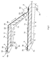
- Fig. 1 shows a plant for transporting textile fabrics with a Conveyor belt 4 for the transport of a textile fabric, by a Textile machine on the conveyor belt 4 passed to a transfer point 5 has been.
- the textile fabric can, for example, a random web, a Fabric, a film, pulp (chopped fiber material) or a nonwoven web 1, as supplied by a card or card 2, or a combination or mixture of the aforementioned materials.
- Fig. 1 shows take-off rollers 35,36 of a carding machine 2, which is a textile fabric in the form of a nonwoven web 1 mechanically on the conveyor belt 4 at the transfer point 5 put down.
- a take-off roll may also be used a nonwoven web 1 transferred to the conveyor belt 4.
- the conveyor belt 4 can also circulates endlessly and is permeable to air so that it flows from the Top of the conveyor belt 4 can allow to its bottom.
- Below the Conveyor belt are a plurality of louvers 6 by means of brackets. 8 attached to a parallel to the conveyor belt 4 extending support structure 10.
- the louvers 6 can with the help of the brackets 8 along the support structure 10, e.g.
- the Air guiding devices 6 a same mutual distance, however, exists also the possibility to set different distances.
- the louvers 6 are pivotally mounted and in different angular positions fixable.
- the pivot joint 14 is arranged on the holder 8. Relative to the plane of movement of the conveyor belt 4 are, for example, angle of attack ⁇ of the louvers 6 between 5 and 90 °, preferably between 10 and 70 °, adjustable.
- angles refer to the underside of the wing-like profile of Air guiding devices 6 in Fig. 1 in relation to the transport plane or to the parallel to the transport plane extending support structure 10th
- the louvers 6 may consist of straight sheets or concave or have convex curvatures.
- wing shape leads to an increase in the air velocity in the area between the louvers 6.
- the wing shape be designed so that the curvature of the wing contour is towards the support structure 10 is progressively reinforced.
- the distance of the support structure 10 to the conveyor belt can also be variably adjustable.
- the adjustable distance of the conveyor belt facing edge 9 of the louvers 6 is set so that the edge 9 of the louvers the Conveyor belt not touched. Depending on the material of the textile fabric can also a greater distance may be required.
- the louvers 6 steer those of the conveyor belt 4, on its underside entrained air and thereby generate an air flow through the textile Sheet and the conveyor belt 4 therethrough, whereby the adhesion of the textile fabric or the nonwoven web 1 on the conveyor belt 4 in high Dimensions is increased.
- Modern high-speed textile machines allow production speeds of over 200 m / min, even Production speeds of over 500 m / min are sought.
- the described Plant for transporting textile fabrics is for such high transport speeds, since the adhesion of the nonwoven web 1 with increasing Speed is automatically increased, causing a disruption of the Uniformity of a delicate textile fabric due to air turbulence can be excluded.
- one of the louvers 6 is with the conveyor belt 4 facing edge 9 on the transfer point 5 opposite Bottom of the conveyor belt 4.
- the edge 9 below the Axle of the doffer roll 36 run.
- For the start-up operation may additionally include a suction device 34 for the area be provided before or behind (Fig. 1) of the transfer point 5, the short while of the startup mode and when reaching a higher conveyor belt speed for example, via a flap 38 and stopping a Fan can be switched off again.
- the suction device 34 when reaching a conveyor belt speed of at least 80 m / min are switched off.
- the support structure 10 may be with devices not shown in the drawings Be provided with the help of the louvers 6 groups in terms of Angle and distance to the conveyor belt and / or the position of the louvers 6 are adjustable relative to the transfer point 5.
- angle and distance to the conveyor belt under consideration the transport speed and / or the basis weight of the textile fabric 1 and / or the fiber specification of the textile fabric 1 automatically be set.
- an air deflector 22 is arranged, the of the air conveyor 4 entrained air deflected in front of the deflection roller 20. additionally can at the guide roller 20 a Heilabstreif adopted 28 in the form of a doctor blade be provided, which strips the entrained by the guide roller 20 air.
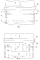
- Fig. 2 shows a plant for transporting textile fabrics 1, in the two nonwoven webs 1a, 1b are brought together on a lower conveyor belt 4.
- the nonwoven webs 1a, 1b can be fed from different carding machines or derive from a double buyer
- Both the upper conveyor belt 4a and the lower conveyor belt 4b are endlessly circulating and with those already described in connection with FIG Provided louvers 6.
- a roller 40 is arranged, for example consist of a smooth roll, a disk roll or a screen roll can and the nonwoven web 1a passes to the lower conveyor belt 4b.
- the louvers generate a high volume of air flow through the nonwoven web and the conveyor belt 4.
- FIG. 3 shows a plan view of the exemplary embodiment according to FIG. 1.
- Fig. 4 shows another embodiment of the louvers in which the Three-lane air ducts are with in edge regions 18 of the conveyor belt 4th arranged portions 6'a, 6'b and a central portion 6'c, the opposite the recessed in the edge region portions 6'a, 6'b is set back.
- the middle spoiler 6c ' also another angle and a have another distance to the conveyor belt 4.
- Fig. 5 shows another embodiment of the louvers 6 ", which is about the entire working width of the conveyor belt 4 extend.
- the in Figs. 4 to 6 illustrated arrow-shaped louvers 6 ', 6 ", 6"' allow an additional Cross-component of the air flow, which is either only in one edge area ( Figures 4 and 6) or over the entire working width is effective.
- Fig. 6 shows a side view of the embodiment of Fig. 5.
- the louvers 6 "are arranged in a puck-like manner one behind the other.
- FIGS. 5 and 6 is not an angle of attack of the louvers 6 "adjustable to the conveyor belt 4, but only the distance to the conveyor belt.
- Fig. 7 shows a further embodiment of the spoilers 6 "', the only are provided in an edge region 18 of the conveyor belt 4.
- Fig. 8 shows an embodiment of FIG. 7, wherein the louvers 6 'have a curvature opposite that of FIG. 7.
Landscapes
- Engineering & Computer Science (AREA)
- Textile Engineering (AREA)
- Preliminary Treatment Of Fibers (AREA)
Abstract
Description
Die Erfindung betrifft eine Anlage sowie ein Verfahren zum Transportieren von textilen
Flächengebilden nach dem Oberbegriff des Anspruchs 1 bzw. Anspruch 20, sowie
eine Anlage und ein Verfahren zum Herstellen von Vliesbahnen nach dem Oberbegriff
des Anspruchs 16 bzw. 22.The invention relates to a system and a method for transporting textile
Fabrics according to the preamble of
Derartige Anlagen sind beispielsweise aus der EP 0 817 875 A bekannt. Bei der bekannten Anlage wird mindestens eine Vliesbahn mechanisch auf ein permeable und besaugtes Transportband übergeben, wobei das Transportband insbesondere an der Übergabestelle mit Hilfe eines Absaugkastens besaugt wird. Nachteilig ist hierbei, dass zur Besaugung des Transportbandes mehrere über die Länge des Transportbandes angeordnete Absaugeinrichtungen benötigt werden, die in ihrer Absaugintensität aufeinander abgestimmt sein müssen und die zu einem hohen Energieverbrauch führen.Such systems are known, for example, from EP 0 817 875 A. In the known Plant at least one nonwoven web mechanically on a permeable and passed over sucked conveyor belt, wherein the conveyor belt in particular at the Transfer point is sucked using a suction box. The disadvantage here is that for the suction of the conveyor belt several over the length of the conveyor belt arranged suction devices are needed in their Absaugintensität need to be coordinated and which leads to a high energy consumption to lead.
Der Erfindung liegt die Aufgabe zugrunde, eine Anlage und ein Verfahren zum Transportieren von textilen Flächengebilden bzw. zum Herstellen von Vliesbahnen zu schaffen, die den Transport von textilen Flächengebilden auch bei hohen Transportgeschwindigkeiten ohne permanente Untersaugung durch Absaugeinrichtungen ermöglicht.The invention is based on the object, a system and a method for Transporting textile fabrics or for producing nonwoven webs to create the transport of textile fabrics even at high transport speeds without permanent suction by suction devices allows.
Zur Lösung dieser Aufgabe dienen die Merkmale der Ansprüche 1,16,20 und 22. Die
Erfindung sieht in vorteilhafter Weise vor, dass auf der dem textilen Flächengebilde
abgewandten Seite des Transportbandes mehrere sich quer zu dem Transportbandes
erstreckende Luftleiteinrichtungen angeordnet sind, die die von dem Transportband
mitgeführte Luft auf der dem textilen Flächengebilde abgewandten Seite umlenken.
Die Erfindung ermöglicht in vorteilhafter Weise den Transport von textilen
Flächengebilden mit hoher Transportgeschwindigkeit von über 100 m/min ohne eine
permanente Besaugung der Transportbänder durch den Einsatz von Absaugeinrichtungen
auf deren Unterseite. Der für den Transport mit hohen Transportgeschwindigkeiten
erforderliche Ansaugluftstrom wird allein durch die Umlenkung der
an der Unterseite des Transportbandes mitgeführten Luft erzielt. Dabei ergibt sich
ein proportionaler Zusammenhang zwischen der Transportbandgeschwindigkeit und
der Haftkraft des textilen Flächengebildes auf dem Transportband. Da die Anlage
keine Absaugeinrichtungen benötigt, entfällt das Erfordernis einer Regelung der Absaugeinrichtungen.
Außerdem entfällt der Stromverbrauch der Absaugeinrichtungen,
so dass nicht nur die Anlagekosten sondern auch die Betriebskosten reduziert
werden können.To achieve this object are the features of
Die dem Transportband zugewandte Kante der Luftleiteinrichtungen verläuft mit geringem, vorzugsweise einstellbarem Abstand von dem Transportband. Der geringe Abstand der Luftleiteinrichtungen von dem Transportband stellt sicher, dass der weitaus überwiegende Teil der von dem Transportband auf der Unterseite mitgeführten Luft umgelenkt werden kann, um die gewünschte Luftströmung durch das textile Flächengebilde und das Transportband zu erzielen. Dadurch, dass der Abstand einstellbar ist, ergibt sich die Möglichkeit, die Absaugleistung einzustellen. Vorzugsweise wird allerdings ein Abstand zwischen 0,1 und 10 mm eingestellt.The conveyor belt facing edge of the louvers runs along low, preferably adjustable distance from the conveyor belt. The low one Distance of the louvers from the conveyor belt ensures that the By far the greater part of the transport belt carried on the underside Air can be diverted to the desired air flow through the air To achieve textile fabrics and the conveyor belt. Because of the distance is adjustable, there is the possibility to adjust the suction power. Preferably, however, a distance between 0.1 and 10 mm is set.
Die Luftleiteinrichtungen sind vorzugsweise auf einer mit Abstand von dem Transportband verlaufenden Tragstruktur ortsfest befestigt oder alternativ parallel und in Längsrichtung zu dem Transportband verschiebbar befestigt. Auch die Parallelverschiebung der Luftleiteinrichtungen in Längsrichtung des Transportbandes ermöglicht eine individuelle Anpassung des Luftstroms an spezielle Erfordernisse in bestimmten Streckenabschnitten des Transportbandes. Vorzugsweise haben die Luftleiteinrichtungen in Transportrichtung einen gleichen Abstand voneinander.The louvers are preferably at a distance from the conveyor belt stationary supporting structure fixed fixed or alternatively parallel and in Slidably mounted longitudinally to the conveyor belt. Also the parallel shift allows the louvers in the longitudinal direction of the conveyor belt an individual adjustment of the air flow to specific requirements in certain Track sections of the conveyor belt. Preferably, the louvers have in the transport direction an equal distance from each other.
Bei einem bevorzugten Ausführungsbeispiel sind die Luftleiteinrichtungen um eine parallel zu dem Transportband und quer zur Transportrichtung verlaufenden Achse verschwenkbar. Auf diese Weise ist der Abstand der Luftleiteinrichtungen von dem Transportband in einfacher Weise und schnell einstellbar.In a preferred embodiment, the louvers are one parallel to the conveyor belt and transverse to the direction of transport axis pivotable. In this way, the distance of the louvers from the Conveyor belt in a simple manner and quickly adjustable.
Bei einem Ausführungsbeispiel ist vorgesehen, dass die Luftleiteinrichtungen nur im Randbereich des Transportbandes angeordnet sind. In diesem Fall wird das textile Flächengebilde insbesondere durch seine angesaugten Randbereiche auf dem Transportband gehalten.In one embodiment, it is provided that the louvers only in Edge region of the conveyor belt are arranged. In this case, the textile Sheet material in particular by its sucked edge areas on the Held conveyor belt.
Nach einem weiteren Ausführungsbeispiel kann vorgesehen sein, dass Luftleiteinrichtungen über die gesamte Arbeitsbreite des Transportbandes oder nur im Randbereich in abwechselnder Anordnung vorgesehen sind. Dabei können auch mehrere Luftleiteinrichtungen des gleichen Typs hintereinander angeordnet sein.According to a further embodiment, it can be provided that air guiding devices over the entire working width of the conveyor belt or only in the edge area are provided in an alternating arrangement. It can also several Air guiding devices of the same type can be arranged one behind the other.
Die Luftleiteinrichtungen können unter einem Winkel von ca. 5 bis 90° relativ zu der Bewegungsebene des Transportbandes verlaufen.The louvers can at an angle of about 5 to 90 ° relative to the Movement level of the conveyor belt run.
Die Luftleiteinrichtungen weisen gemäß einer bevorzugten Ausführungsform im Querschnitt ein aerodynamisches Flügelprofil auf. Die aerodynamische Flügelform unterstützt die Umlenkung der dem Transportband mitgeführten Luft und erhöht dadurch die Absaugleistung und damit die Haftung des textilen Flächengebildes auf dem Transportband.The louvers have according to a preferred embodiment in Cross section of an aerodynamic wing profile. The aerodynamic wing shape supports the deflection of the air entrained in the conveyor belt and increases thereby the suction power and thus the adhesion of the textile fabric the conveyor belt.
Gemäß einem weiteren Ausführungsbeispiel ist vorgesehen, dass die über die gesamte Arbeitsbreite verlaufenden Luftleiteinrichtungen in der Draufsicht pfeilförmig verlaufen, wobei die Pfeilspitze in der Mitte des Transportbandes angeordnets ein kann. Eine derartige Gestaltung der Luftleiteinrichtungen ermöglicht es, eine zusätzliche Querkomponente der Luftströmung zu erzeugen. Nach einer weiteren Alternative kann die pfeilförmige Anordnung der Luftleiteinrichtungen in Draufsicht auch nur im Randbereich vorgesehen sein.According to a further embodiment, it is provided that the over the entire Working width extending louvers arrowhead in plan view run, with the arrowhead in the middle of the conveyor belt arranged a can. Such a design of the louvers allows an additional Generate transverse component of the air flow. For another alternative can the arrow-shaped arrangement of the louvers in plan view also be provided only in the border area.
Vorzugsweise ist vorgesehen, dass vor Umlenkbereichen, in denen das Transportband umgelenkt wird, oder an Übergabestellen, an denen das Transportband das textile Flächengebilde erhält, flügelförmige Luftabweiser unterhalb des Transportbandes angeordnet sind. Die Luftabweiser verhindern Luftverwirbelungen an den Umlenkbereichen und Übergabestellen.It is preferably provided that in front of deflection areas in which the conveyor belt is redirected, or to transfer points, where the conveyor belt the textile fabric receives, wing-shaped air deflector below the conveyor belt are arranged. The air deflectors prevent air turbulence to the Deflection areas and transfer points.
Außerdem können an rotierenden Teilen zur Vermeidung von Schleppluft des rotierenden Teils Luftabstreifeinrichtungen, beispielsweise in Form eines Rakels, angeordnet sein.In addition, rotating parts can be used to prevent the trailing air from rotating Part Luftabstreifeinrichtungen arranged, for example in the form of a doctor blade be.
Derartige Luftabstreifeinrichtungen sind beispielsweise an den Umlenkwalzen des Transportbandes angeordnet, um zu vermeiden, dass die von den Umlenkwalzen mitgeführte Schleppluft eine Luftströmung von unten in Richtung auf das Transportband erzeugt.Such Luftabstreifeinrichtungen are, for example, to the guide rollers of the Conveyor belt arranged to avoid that from the guide rollers entrained trailing air from below in the direction of the conveyor belt generated.
Mehrere Luftleiteinrichtungen können gruppenweise gemeinsam verstellbar sein. Der Winkel und der Abstand der Luftleiteinrichtungen zu dem Transportband und/oder der gegenseitige Abstand der Luftleiteinrichtungen in Transportrichtung können in Abhängigkeit von der Transportgeschwindigkeit und/oder des Flächengewichtes und/oder der Faserspezifikation des textilen Flächengebildes automatisch einstellbar sein.Several louvers may be adjustable in groups together. The angle and the distance of the louvers to the conveyor belt and / or the mutual distance of the louvers in the transport direction can depend on the transport speed and / or basis weight and / or the fiber specification of the textile fabric automatically be adjustable.
In den Zwischenräumen zwischen den Luftleiteinrichtungen kann im Bereich von Übergabestellen, an denen das textile Flächengebilde auf das Transportband übertragen wird, mit Hilfe einer Absaugeinrichtung ein Absaugluftstrom für ein kurzes Zeitintervall zur Anfahrunterstützung erzeugt werden. Eine derartige Absaugeinrichtung kann das Anhaften des textilen Flächengebildes im Anfahrbetrieb unterstützen und wird bei Erreichen der Transportgeschwindigkeit oder bereits vorher, beispielsweise ab einer Transportbandgeschwindigkeit von 80 m/min, abgeschaltet. In the spaces between the louvers may be in the range of Transfer points at which the textile fabric is transferred to the conveyor belt is, using a suction device, a suction air flow for a short Time interval for starting assistance to be generated. Such a suction device can support the adhesion of the textile fabric during start-up operation and will be on reaching the transport speed or already before, for example, from a conveyor belt speed of 80 m / min, switched off.
Die Erfindung betrifft desweiteren eine Anlage zum Herstellen von Vliesbahnen mit
mindestens einer Krempel oder Karde und mit mindestens einem besaugten permeablen
Transportband für den Transport der von der Karde und/oder Krempel erzeugten
Vliesbahn, wobei diese Anlage mit einer Transportanlage mit den Merkmalen
der Ansprüche 1 bis 15 versehen ist.The invention further relates to a system for producing nonwoven webs with
at least one card or card and with at least one evacuated permeable
Conveyor belt for the transport of the card and / or carding produced
Nonwoven web, this system with a transport system with the features
of
Dabei kann das Transportband eine mechanisch erzeugte Vliesbahn oder eine aerodynamisch erzeugte Vliesbahn transportieren.In this case, the conveyor belt can be a mechanically produced nonwoven web or an aerodynamic transport generated nonwoven web.
Die Anlage zum Herstellen von Vliesbahnen kann auch mehrere Vliesbahnen übereinander auf ein einziges Transportband übertragen.The plant for producing nonwoven webs can also have several nonwoven webs one above the other transferred to a single conveyor belt.
Die Vliesbahnen können dabei von verschiedenen Krempeln erzeugt werden oder von einer Doppelabnehmerkrempel stammen, wobei jeweils eine Vliesbahn von einem Transportband übernommen wird. Eine obere Vliesbahn wird dann von einem oberen Transportband auf eine untere Vliesbahn auf einem unteren Transportband übergeben und aufgrund der Luftströmung durch das Transportband auf der darunterliegenden Vliesbahn fixiert.The nonwoven webs can be generated by different cards or come from a Doppelabnehmerkrempel, each with a nonwoven web of a Conveyor belt is adopted. An upper nonwoven web is then from a upper conveyor belt on a lower nonwoven web on a lower conveyor belt passed and due to the air flow through the conveyor belt on the underlying Nonwoven web fixed.
Die Anordnung von zwei Transportbändern übereinander hat den weiteren Vorteil, dass die durch das obere Transportband strömende Luft, die auch durch das untere Transportband hindurchgeführt wird, in hohem Maße vergleichmäßigt wird, wodurch die Gefahr von Luftwirbeln stark verringert wird.The arrangement of two conveyor belts one above the other has the further advantage that the air flowing through the upper conveyor belt, which is also through the lower Conveyor belt is passed, is highly uniformed, whereby the risk of air turbulence is greatly reduced.
Das erfindungsgemäße Verfahren zum Transportieren von textilen Flächengebilden mit einem permeablen und besaugten Transportband durch Übergeben eines textilen Flächengebildes auf das bewegte Transportband sieht vor, dass eine erhöhte Anpresskraft auf das textile Flächengebilde durch Umlenken der auf der Unterseite des Transportbandes mitgeführten Schleppluft erzeugt wird.The inventive method for transporting textile fabrics with a permeable and evacuated conveyor belt by passing a textile Sheet on the moving conveyor belt provides that increased Contact pressure on the textile fabric by deflecting the on the underside of the conveyor belt entrained drag air is generated.
Im folgenden werden unter Bezugnahme auf die Zeichnungen Ausführungsbeispiele der Erfindung näher erläutert: In the following, with reference to the drawings, embodiments the invention explained in more detail:
Es zeigen:
- Fig. 1
- ein erstes Ausführungsbeispiel eines Transportbandes mit Luftleiteinrichtungen auf dessen Unterseite,
- Fig. 2
- das Zusammenführen von textilen Flächengebilden auf zwei unterschiedlichen Transportbändern,
- Fig. 3
- eine Draufsicht auf das Ausführungsbeispiel der Fig. 1, und
- Fign.4 bis 8
- weitere Ausführungsbeispiele für Luftleiteinrichtungen, und
- Fig. 1
- a first embodiment of a conveyor belt with louvers on its underside,
- Fig. 2
- the merging of textile fabrics on two different conveyor belts,
- Fig. 3
- a plan view of the embodiment of Fig. 1, and
- Fign.4 to 8
- Further embodiments of louvers, and
Fig. 1 zeigte eine Anlage zum Transportieren von textilen Flächengebilden mit einem
Transportband 4 für den Transport eines textilen Flächengebildes, das von einer
Textilmaschine auf das Transportband 4 an einer Übergabestelle 5 übergeben
worden ist. Das textile Flächengebilde kann beispielsweise aus einem Wirrvlies, einem
Gewebe, einer Folie, Pulpe (gehäkseltes Fasermaterial) oder aus einer Vliesbahn
1, wie sie von einer Karde oder Krempel 2 geliefert wird, oder einer Kombination
oder Mischung der vorgenannten Materialien bestehen.Fig. 1 shows a plant for transporting textile fabrics with a
Fig. 1 zeigt Abnahmewalzen 35,36 einer Krempel 2, die ein textiles Flächengebilde
in Form einer Vliesbahn 1 mechanisch auf das Transportband 4 an der Übergabestelle
5 ablegen. Anstelle der Abnahmewalzen 35,36 kann auch eine Abnehmerwalze
eine Vliesbahn 1 auf das Transportband 4 übertragen. Das Transportband 4 kann
auch endlos umlaufen und ist luftdurchlässig, damit es eine Luftströmung von der
Oberseite des Transportbandes 4 zu seiner Unterseite zulassen kann. Unterhalb des
Transportbandes sind mehrere Luftleiteinrichtungen 6 mit Hilfe von Halterungen 8
an einer parallel zu dem Transportband 4 verlaufenden Tragstruktur 10 befestigt.
Die Luftleiteinrichtungen 6 können mit Hilfe der Halterungen 8 längs der Tragstruktur
10, z.B. einem Rohr, längs verschoben werden, um einen gewünschten
Abstand zwischen den Luftleiteinrichtungen 6 einzustellen. Vorzugsweise haben die
Luftleiteinrichtungen 6 einen gleichen gegenseitigen Abstand, allerdings besteht
auch die Möglichkeit unterschiedliche Abstände einzustellen. An den Halterungen 8
sind die Luftleiteinrichtungen 6 schwenkbar gelagert und in unterschiedliche Winkelstellungen
fixierbar. In Fig. 1 ist das Schwenkgelenk 14 an der Halterung 8 angeordnet.
Relativ zur Bewegungsebene des Transportbandes 4 sind beispielsweise Anstellwinkel
α der Luftleiteinrichtungen 6 zwischen 5 und 90°, vorzugsweise zwischen
10 und 70°, einstellbar.Fig. 1 shows take-off
Die Winkelangaben beziehen sich auf die Unterseite des flügelartigen Profils der
Luftleiteinrichtungen 6 in Fig. 1 in Relation zur Transportebene bzw. zu der parallel
zur Transportebene verlaufenden Tragstruktur 10.The angles refer to the underside of the wing-like profile of
Die Luftleiteinrichtungen 6 können aus geraden Blechen bestehen oder auch konkave
oder konvexe Krümmungen aufweisen.The
Die in den Fign. 1 und 2 gezeigte Flügelform führt zu einer Erhöhung der Luftgeschwindigkeit
im Bereich zwischen den Luftleiteinrichtungen 6. Dabei kann die Flügelform
so gestaltet sein, dass die Krümmung der Flügelkontur sich in Richtung auf
die Tragstruktur 10 progressiv verstärkt.The in Figs. 1 and 2 wing shape leads to an increase in the air velocity
in the area between the
Zur Einstellung des Winkels und des Abstandes der Luftleiteinrichtungen 6 von dem
Transportband 4 kann auch der Abstand der Tragstruktur 10 zu dem Transportband
variabel einstellbar sein.To adjust the angle and the distance of the
Der einstellbare Abstand der dem Transportband zugewandten Kante 9 der Luftleiteinrichtungen
6 ist so eingestellt, dass die Kante 9 der Luftleiteinrichtungen das
Transportband nicht berührt. Je nach Material des textilen Flächengebildes kann
auch ein größerer Abstand erforderlich sein.The adjustable distance of the conveyor
Die Luftleiteinrichtungen 6 lenken die von dem Transportband 4, auf dessen Unterseite
mitgeführte Luft um und erzeugen dadurch eine Luftströmung durch das textile
Flächengebilde und das Transportband 4 hindurch, wodurch die Haftung des
textilen Flächengebildes bzw. der Vliesbahn 1 auf dem Transportband 4 in hohem
Maße erhöht wird. Dabei ergibt sich eine Proportionalität des Anpressdrucks in Abhängigkeit
von der Transportgeschwindigkeit. Moderne Hochgeschwindigkeitstextilmaschinen
erlauben Produktionsgeschwindigkeiten von über 200 m/min, wobei sogar
Produktionsgeschwindigkeiten von über 500 m/min angestrebt werden. Die beschriebene
Anlage zum Transportieren von textilen Flächengebilden ist für derartig
hohe Transportgeschwindigkeiten geeignet, da die Haftung der Vliesbahn 1 bei zunehmender
Geschwindigkeit automatisch erhöht wird, so dass eine Störung der
Gleichmäßigkeit eines empfindlichen textilen Flächengebildes durch Luftverwirbelungen
ausgeschlossen werden kann.The
Vorzugsweise befindet sich eine der Luftleiteinrichtungen 6 mit der dem Transportband
4 zugewandten Kante 9 auf der der Übergabestelle 5 gegenüberliegenden
Unterseite des Transportbandes 4. Beispielsweise kann die Kante 9 unterhalb der
Achse der Abnehmerwalze 36 verlaufen.Preferably, one of the
Für den Anlaufbetrieb kann zusätzlich eine Absaugeinrichtung 34 für den Bereich
vor oder hinter (Fig. 1) der Übergabestelle 5 vorgesehen sein, die kurzzeitig während
des Anlaufbetriebs eingeschaltet und bei Erreichen einer höheren Transportbandgeschwindigkeit
beispielsweise über eine Klappe 38 und Stillsetzung eines
Ventilators wieder abgeschaltet werden kann. Beispielsweise kann die Absaugeinrichtung
34 bei Erreichen einer Transportbandgeschwindigkeit von mindestens 80
m/min abgeschaltet werden.For the start-up operation may additionally include a
Die Tragstruktur 10 kann mit in den Zeichnungen nicht dargestellten Einrichtungen
versehen sein, mit deren Hilfe die Luftleiteinrichtungen 6 gruppenweise bezüglich
Winkel und Abstand zum Transportband und/oder der Position der Luftleiteinrichtungen
6 relativ zu der Übergabestelle 5 einstellbar sind.The
Desweiteren können Winkel und Abstand zum Transportband unter Berücksichtigung
der Transportgeschwindigkeit und/oder des Flächengewichtes des textilen Flächengebildes
1 und/oder der Faserspezifikation des textilen Flächengebildes 1 automatisch
eingestellt werden.Furthermore, angle and distance to the conveyor belt under consideration
the transport speed and / or the basis weight of the
An rotierenden Teilen z.B. der Walze 20 bis in den Keil zwischen dem zulaufenden
Transportband und der Walze 20 ist ein Luftabweiser 22 angeordnet, der die von
dem Transportband 4 mitgeschleppte Luft vor der Umlenkwalz 20 umlenkt. Zusätzlich
kann an der Umlenkwalze 20 eine Luftabstreifeinrichtung 28 in Form eines Rakels
vorgesehen sein, die die von der Umlenkwalze 20 mitgeführte Luft abstreift.On rotating parts e.g. the
Fig. 2 zeigt eine Anlage zum Transportieren von textilen Flächengebilden 1, bei der
zwei Vliesbahnen 1a,1b auf ein unteres Transportband 4 zusammengeführt werden.
Die Vliesbahnen 1a,1b können von unterschiedlichen Krempelmaschinen zugeführt
werden oder von einer Doppelabnehmerkrempel stammen.Fig. 2 shows a plant for transporting
Sowohl das obere Transportband 4a als auch das untere Transportband 4b sind
endlos umlaufend und mit den bereits im Zusammenhang mit Fig. 1 beschriebenen
Luftleiteinrichtungen 6 versehen. An der Übergabestelle 7, an der die Vliesbahnen
1a,1b zusammengeführt werden, ist eine Walze 40 angeordnet, die beispielsweise
aus einer glatten Walze, aus einer Scheibenwalze oder einer Siebwalze bestehen
kann und die die Vliesbahn 1a an das untere Transportband 4b übergibt.Both the
Die Luftleiteinrichtungen erzeugen einen hohen Luftvolumenstrom durch die Vliesbahn
und das Transportband 4.The louvers generate a high volume of air flow through the nonwoven web
and the
Bei der Anordnung gemäß Fig. 2 wird die durch das Transportband 4a hindurchgesogene
Luft in hohem Maße vergleichmäßigt, so dass dem unteren Transportband
4b ein ausreichend großer Volumenstrom zugeführt werden kann, der gleichmäßig
über die gesamte Arbeitsbreite verteilt ist.In the arrangement of FIG. 2, the sucked through the
Fig. 3 zeigt eine Draufsicht des Ausführungsbeispiels gemäß Fig. 1.FIG. 3 shows a plan view of the exemplary embodiment according to FIG. 1.
Fig. 4 zeigt eine andere Ausführungsform der Luftleiteinrichtungen, bei denen die
Luftleiteinrichtungen dreiteilig sind mit in Randbereichen 18 des Transportbandes 4
angeordneten Abschnitten 6'a,6'b und einem mittleren Abschnitt 6'c, der gegenüber
den im Randbereich vorgesehenen Abschnitten 6'a,6'b zurückversetzt ist. Dabei
kann die mittlere Luftleiteinrichtung 6c' auch einen anderen Anstellwinkel und einen
anderen Abstand zu dem Transportband 4 aufweisen.Fig. 4 shows another embodiment of the louvers in which the
Three-lane air ducts are with in
Fig. 5 zeigt eine weitere Ausführungsform der Luftleiteinrichtungen 6", die sich über
die gesamte Arbeitsbreite des Transportbandes 4 erstrecken. Die in den Fign. 4 bis
6 dargestellten pfeilförmigen Luftleiteinrichtungen 6',6",6"' ermöglichen eine zusätzliche
Querkomponente der Luftströmung, die entweder nur in einem Randbereich
(Fig. 4 und 6) oder auch über die gesamte Arbeitsbreite wirksam ist.Fig. 5 shows another embodiment of the
Fig. 6 zeigt dabei eine Seitenansicht des Ausführungsbeispiels der Fig. 5. Die Luftleiteinrichtungen
6" sind dabei pflugscharähnlich hintereinander angeordnet.Fig. 6 shows a side view of the embodiment of Fig. 5. The
Bei dem Ausführungsbeispiel der Fign. 5 und 6 ist kein Anstellwinkel der Luftleiteinrichtungen
6" zu dem Transportband 4 einstellbar, sondern lediglich der Abstand zu
dem Transportband.In the embodiment of FIGS. 5 and 6 is not an angle of attack of the
Fig. 7 zeigt ein weiteres Ausführungsbeispiel der Luftleiteinrichtungen 6"', die lediglich
in einem Randbereich 18 des Transportbandes 4 vorgesehen sind.Fig. 7 shows a further embodiment of the
Fig. 8 zeigt ein Ausführungsbeispiel gemäß Fig. 7, bei der die Luftleiteinrichtungen 6' eine im Vergleich zu Fig. 7 entgegengesetzte Krümmung aufweisen.Fig. 8 shows an embodiment of FIG. 7, wherein the louvers 6 'have a curvature opposite that of FIG. 7.
Claims (22)
dadurch gekennzeichnet, dass auf der dem textilen Flächengebilde (1) abgewandten Seite des Transportbandes (4) mehrere sich quer zu dem Transportband (4) erstreckende Luftleiteinrichtungen (6,6'a,6'b,6",6"',6"") angeordnet sind, die die von dem Transportband (4) auf der dem textilen Flächengebilde (1) abgewandten Seite mitgeführte Luft umlenken.Plant for transporting textile fabrics (1), comprising at least one permeable and evacuated conveyor belt (4) for transporting a textile fabric (1, 1a, 1b) transported by a textile machine onto the conveyor belt (4) at a transfer point (5) has been handed over,
characterized in that on the textile fabric (1) facing away from the conveyor belt (4) a plurality of transversely to the conveyor belt (4) extending louvers (6,6'a, 6'b, 6 ", 6"', 6 "") are arranged, which deflect the air entrained by the conveyor belt (4) on the side facing away from the textile fabric (1).
Priority Applications (3)
| Application Number | Priority Date | Filing Date | Title |
|---|---|---|---|
| DE50108324T DE50108324D1 (en) | 2001-09-25 | 2001-09-25 | Plant and method for transporting textile fabrics |
| EP01122930A EP1295973B1 (en) | 2001-09-25 | 2001-09-25 | Apparatus and method for transporting a textile sheet |
| US10/253,876 US6729465B2 (en) | 2001-09-25 | 2002-09-25 | Plant and a method for transporting textile fabrics |
Applications Claiming Priority (1)
| Application Number | Priority Date | Filing Date | Title |
|---|---|---|---|
| EP01122930A EP1295973B1 (en) | 2001-09-25 | 2001-09-25 | Apparatus and method for transporting a textile sheet |
Publications (2)
| Publication Number | Publication Date |
|---|---|
| EP1295973A1 true EP1295973A1 (en) | 2003-03-26 |
| EP1295973B1 EP1295973B1 (en) | 2005-12-07 |
Family
ID=8178718
Family Applications (1)
| Application Number | Title | Priority Date | Filing Date |
|---|---|---|---|
| EP01122930A Expired - Lifetime EP1295973B1 (en) | 2001-09-25 | 2001-09-25 | Apparatus and method for transporting a textile sheet |
Country Status (3)
| Country | Link |
|---|---|
| US (1) | US6729465B2 (en) |
| EP (1) | EP1295973B1 (en) |
| DE (1) | DE50108324D1 (en) |
Cited By (2)
| Publication number | Priority date | Publication date | Assignee | Title |
|---|---|---|---|---|
| EP1672110A1 (en) | 2004-12-16 | 2006-06-21 | Asselin-Thibeau | Method and device for the transport of carded or air-laid nonwovens |
| EP2703534B1 (en) * | 2012-08-29 | 2017-10-18 | Trützschler GmbH & Co. KG | Feed system for textile processing machinery |
Families Citing this family (2)
| Publication number | Priority date | Publication date | Assignee | Title |
|---|---|---|---|---|
| DE102012110975A1 (en) | 2012-06-19 | 2013-12-19 | Trützschler GmbH + Co KG Textilmaschinenfabrik | System for transporting textile fabrics, has air-permeable conveyor belt arranged under suction hood with suction opening, where distance between suction hood and conveyor belt is adjusted by rotating or pivoting around bearing |
| WO2019241316A1 (en) * | 2018-06-12 | 2019-12-19 | Thyssenkrupp Industrial Solutions (Usa), Inc. | Wind deflection apparatuses for trough conveyors |
Citations (5)
| Publication number | Priority date | Publication date | Assignee | Title |
|---|---|---|---|---|
| DE3116628A1 (en) * | 1981-04-27 | 1982-11-11 | Friedrich 4670 Lünen Abdinghoff | Deflectors arranged in the rear part of a car with a rear window and intended for dirt, rain and the like |
| US4534086A (en) * | 1983-05-05 | 1985-08-13 | Ernst Fehrer | Apparatus for making fibrous webs |
| US5007137A (en) * | 1989-01-18 | 1991-04-16 | Hergeth Hollingsworth Gmbh | Carding apparatus |
| DE19511904A1 (en) * | 1995-03-31 | 1996-10-10 | Hollingsworth Gmbh | Plant and method for producing nonwoven webs |
| US5584101A (en) * | 1994-09-30 | 1996-12-17 | Thibeau (Sa) | Apparatus for removing and conveying a fiber web at high speed from the outlet from a carder |
Family Cites Families (5)
| Publication number | Priority date | Publication date | Assignee | Title |
|---|---|---|---|---|
| US3862472A (en) * | 1973-01-05 | 1975-01-28 | Scott Paper Co | Method for forming a low basis weight non-woven fibrous web |
| DE2361313A1 (en) * | 1973-01-17 | 1974-07-18 | Fehrer Ernst | METHOD OF SPINNING TEXTILE FIBERS |
| US4130915A (en) * | 1977-09-19 | 1978-12-26 | Scott Paper Company | Carding operation for forming a fibrous structure |
| US5093962A (en) * | 1987-07-20 | 1992-03-10 | Chicopee | Method of forming webs without confining ducts |
| US4904439A (en) * | 1988-07-18 | 1990-02-27 | Johnson & Johnson | Method of making a non-woven fiber web using a multi-headed ductless webber |
-
2001
- 2001-09-25 DE DE50108324T patent/DE50108324D1/en not_active Expired - Lifetime
- 2001-09-25 EP EP01122930A patent/EP1295973B1/en not_active Expired - Lifetime
-
2002
- 2002-09-25 US US10/253,876 patent/US6729465B2/en not_active Expired - Lifetime
Patent Citations (5)
| Publication number | Priority date | Publication date | Assignee | Title |
|---|---|---|---|---|
| DE3116628A1 (en) * | 1981-04-27 | 1982-11-11 | Friedrich 4670 Lünen Abdinghoff | Deflectors arranged in the rear part of a car with a rear window and intended for dirt, rain and the like |
| US4534086A (en) * | 1983-05-05 | 1985-08-13 | Ernst Fehrer | Apparatus for making fibrous webs |
| US5007137A (en) * | 1989-01-18 | 1991-04-16 | Hergeth Hollingsworth Gmbh | Carding apparatus |
| US5584101A (en) * | 1994-09-30 | 1996-12-17 | Thibeau (Sa) | Apparatus for removing and conveying a fiber web at high speed from the outlet from a carder |
| DE19511904A1 (en) * | 1995-03-31 | 1996-10-10 | Hollingsworth Gmbh | Plant and method for producing nonwoven webs |
Cited By (2)
| Publication number | Priority date | Publication date | Assignee | Title |
|---|---|---|---|---|
| EP1672110A1 (en) | 2004-12-16 | 2006-06-21 | Asselin-Thibeau | Method and device for the transport of carded or air-laid nonwovens |
| EP2703534B1 (en) * | 2012-08-29 | 2017-10-18 | Trützschler GmbH & Co. KG | Feed system for textile processing machinery |
Also Published As
| Publication number | Publication date |
|---|---|
| EP1295973B1 (en) | 2005-12-07 |
| DE50108324D1 (en) | 2006-01-12 |
| US20030057057A1 (en) | 2003-03-27 |
| US6729465B2 (en) | 2004-05-04 |
Similar Documents
| Publication | Publication Date | Title |
|---|---|---|
| DE4447963B4 (en) | Device for non-contact guiding sheet material | |
| AT392991B (en) | DRYING PART FOR A MACHINE FOR THE PRODUCTION OR PROCESSING OF FIBER STRIPS, ESPECIALLY PAPER STRIPS | |
| EP0725178B1 (en) | Method and device for drying and shrinking of textile fabric | |
| EP1792860B1 (en) | Vacuum web transport device for guiding a running web | |
| DE69409648T3 (en) | Dispositif pour detacher et transporter à grande vitesse un voile fibreux en sortie de carde | |
| DE3841909C2 (en) | ||
| DE60007489T2 (en) | Device for transporting a material web | |
| DE69918653T2 (en) | DEVICE FOR PROMOTING AND GUIDING THE IMPACT STRIP OF A TRACK IN A PAPER MACHINE | |
| DE4029487A1 (en) | Coated paper drying - using blown air to form air cushion to carry web through dryers without contact | |
| DE4013485C2 (en) | Method and device for making the web end run effective in a paper machine dryer section | |
| EP3066239B1 (en) | Nonwoven laying apparatus, and nonwoven laying method | |
| EP1028077B1 (en) | Sheet guiding device for a printing machine | |
| EP1295973B1 (en) | Apparatus and method for transporting a textile sheet | |
| EP0744366B1 (en) | Device for guiding a fibrous web comprising a stationary slide rail | |
| DE2137115A1 (en) | BOW CONVEYOR | |
| EP0785306B1 (en) | Apparatus for guiding web material | |
| DE4035985B4 (en) | Suction process and suction device in a paper machine | |
| WO2004074148A2 (en) | Device for guiding a moving web of fibrous material | |
| EP1354988B1 (en) | Carding machine with air jet doffer | |
| DE4421918C1 (en) | Paper sheet transporting and alignment mechanism | |
| CH627798A5 (en) | PNEUMATIC CLEANING DEVICE ON THE INLET TABLE OF A SPINNING MACHINE. | |
| EP0830478A1 (en) | Device and method for stabilizing a continuous strip of paper in a paper-making machine in the vicinity of a roll | |
| EP2508672B1 (en) | Device for transferring a web in a station of a web production or processing machine | |
| EP1520815B1 (en) | Vacuum transporting device, in particular threading device for a web material in a machine for making or/and finishing a web material | |
| EP1792861B1 (en) | Vacuum belt feeding apparatus for guiding a moving web |
Legal Events
| Date | Code | Title | Description |
|---|---|---|---|
| PUAI | Public reference made under article 153(3) epc to a published international application that has entered the european phase |
Free format text: ORIGINAL CODE: 0009012 |
|
| AK | Designated contracting states |
Kind code of ref document: A1 Designated state(s): AT BE CH CY DE DK ES FI FR GB GR IE IT LI LU MC NL PT SE TR |
|
| AX | Request for extension of the european patent |
Extension state: AL LT LV MK RO SI |
|
| 17P | Request for examination filed |
Effective date: 20030729 |
|
| AKX | Designation fees paid |
Designated state(s): BE DE FR IT |
|
| GRAP | Despatch of communication of intention to grant a patent |
Free format text: ORIGINAL CODE: EPIDOSNIGR1 |
|
| GRAS | Grant fee paid |
Free format text: ORIGINAL CODE: EPIDOSNIGR3 |
|
| GRAA | (expected) grant |
Free format text: ORIGINAL CODE: 0009210 |
|
| AK | Designated contracting states |
Kind code of ref document: B1 Designated state(s): BE DE FR IT |
|
| REF | Corresponds to: |
Ref document number: 50108324 Country of ref document: DE Date of ref document: 20060112 Kind code of ref document: P |
|
| ET | Fr: translation filed | ||
| PLBE | No opposition filed within time limit |
Free format text: ORIGINAL CODE: 0009261 |
|
| STAA | Information on the status of an ep patent application or granted ep patent |
Free format text: STATUS: NO OPPOSITION FILED WITHIN TIME LIMIT |
|
| 26N | No opposition filed |
Effective date: 20060908 |
|
| REG | Reference to a national code |
Ref country code: FR Ref legal event code: PLFP Year of fee payment: 15 |
|
| REG | Reference to a national code |
Ref country code: FR Ref legal event code: PLFP Year of fee payment: 16 |
|
| REG | Reference to a national code |
Ref country code: FR Ref legal event code: PLFP Year of fee payment: 17 |
|
| REG | Reference to a national code |
Ref country code: FR Ref legal event code: PLFP Year of fee payment: 18 |
|
| PGFP | Annual fee paid to national office [announced via postgrant information from national office to epo] |
Ref country code: BE Payment date: 20190925 Year of fee payment: 19 |
|
| PGFP | Annual fee paid to national office [announced via postgrant information from national office to epo] |
Ref country code: DE Payment date: 20200928 Year of fee payment: 20 Ref country code: FR Payment date: 20200925 Year of fee payment: 20 |
|
| PGFP | Annual fee paid to national office [announced via postgrant information from national office to epo] |
Ref country code: IT Payment date: 20200930 Year of fee payment: 20 |
|
| REG | Reference to a national code |
Ref country code: BE Ref legal event code: MM Effective date: 20200930 |
|
| PG25 | Lapsed in a contracting state [announced via postgrant information from national office to epo] |
Ref country code: BE Free format text: LAPSE BECAUSE OF NON-PAYMENT OF DUE FEES Effective date: 20200930 |
|
| REG | Reference to a national code |
Ref country code: DE Ref legal event code: R071 Ref document number: 50108324 Country of ref document: DE |