EP1295542A2 - Schieber für Reissverschluss - Google Patents
Schieber für Reissverschluss Download PDFInfo
- Publication number
- EP1295542A2 EP1295542A2 EP02019973A EP02019973A EP1295542A2 EP 1295542 A2 EP1295542 A2 EP 1295542A2 EP 02019973 A EP02019973 A EP 02019973A EP 02019973 A EP02019973 A EP 02019973A EP 1295542 A2 EP1295542 A2 EP 1295542A2
- Authority
- EP
- European Patent Office
- Prior art keywords
- face
- pull
- guide
- upper stopper
- slide fastener
- Prior art date
- Legal status (The legal status is an assumption and is not a legal conclusion. Google has not performed a legal analysis and makes no representation as to the accuracy of the status listed.)
- Granted
Links
Images


Classifications
-
- A—HUMAN NECESSITIES
- A44—HABERDASHERY; JEWELLERY
- A44B—BUTTONS, PINS, BUCKLES, SLIDE FASTENERS, OR THE LIKE
- A44B19/00—Slide fasteners
- A44B19/24—Details
- A44B19/26—Sliders
-
- A—HUMAN NECESSITIES
- A44—HABERDASHERY; JEWELLERY
- A44B—BUTTONS, PINS, BUCKLES, SLIDE FASTENERS, OR THE LIKE
- A44B19/00—Slide fasteners
- A44B19/24—Details
- A44B19/26—Sliders
- A44B19/30—Sliders with means for locking in position
- A44B19/308—Sliders with means for locking in position in the form of a spring-actuated locking member actuated by the pull member
-
- Y—GENERAL TAGGING OF NEW TECHNOLOGICAL DEVELOPMENTS; GENERAL TAGGING OF CROSS-SECTIONAL TECHNOLOGIES SPANNING OVER SEVERAL SECTIONS OF THE IPC; TECHNICAL SUBJECTS COVERED BY FORMER USPC CROSS-REFERENCE ART COLLECTIONS [XRACs] AND DIGESTS
- Y10—TECHNICAL SUBJECTS COVERED BY FORMER USPC
- Y10T—TECHNICAL SUBJECTS COVERED BY FORMER US CLASSIFICATION
- Y10T24/00—Buckles, buttons, clasps, etc.
- Y10T24/25—Zipper or required component thereof
- Y10T24/2561—Slider having specific configuration, construction, adaptation, or material
- Y10T24/2566—Slider having specific configuration, construction, adaptation, or material including position locking-means attached thereto
- Y10T24/257—Slider having specific configuration, construction, adaptation, or material including position locking-means attached thereto having surface engaging element shifted by reorientation of pull tab
- Y10T24/2571—Resilient or spring biased element
Definitions
- the present invention relates to a pull rotated type slider of a slide fastener, in which a pull of the slider is capable of rotating from a top face to a front face and a bottom face of a body, and an upper stopper provided on a fastener chain opposing this pull rotated type slider.
- a pull rotated type slider in a slide fastener its U-shaped guide lever, which is provided on a body so as to guide a pull for rotating from a top face to a front face and a bottom face of the body, is formed having a T-shaped cross section. Further, the T-shaped guide portion for guiding the pull is so constructed that an inner face at its corner presents a right angle.
- the inner face at the corner of the U-shaped guide lever 110 provided on the body 119 is formed at the right angle and inwardly directed attachment pieces 118 provided on both sides of a front end of the pull 117 are fitted therein.
- Upper stopper provided on the fastener chain, which the pull rotated type slider formed in the aforementioned way is mounted to slidably, is not an upper stopper having any special configuration, but an rectangular upper stopper made of an ordinarily used thermoplastic resin or a metallic upper stopper having a U-shaped cross section. Thus, this is not an upper stopper particularly corresponding to the U-shaped guide lever of the pull rotated type slider.
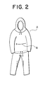
- the slide fastener of the invention is attached to an edge of a mouth portion of a front pocket in a wear such as anorak, as shown in Fig. 2, so as to be used reversibly, and this slide fastener is convenient when it is intended to accommodate the wear into a reversed pocket. Therefore, if the slide fastener is attached to the edge of the mouth portion of the pocket and used reversibly, fastener tapes on front ends relative to the upper stoppers are mounted more or less in a closed state as shown in Fig. 3, for example, so as to form a good appearance pocket.
- the invention has been achieved in views of the above-described problems and a main object of the invention is to provide a slide fastener, in which the pull rotated type slider and/or the upper stopper includes a guide portion for guiding the upper stopper and the guide lever in the pull rotated type slider, which are kept in a contact state with each other when the slider fastener is closed, in the direction that they leave each other in a sliding contact condition, when the pull rotated type slider is operated so as to open the fastener chain, thereby ensuring a start of a smooth opening operation.
- another object of the invention is to provide a slide fastener, in which even if both fastener tapes on front ends relative to the upper stoppers mounted on the fastener chain are disposed in a closed state, that is, such that they approach each other, excessive contact between the guide lever and the upper stoppers is released easily, thereby starting the opening operation of the pull rotated type slider smoothly. Further, it is a further object to provide a slide fastener, in which a smooth opening operation of the pull rotated type slider is achieved and which comprises a pull rotated type slider which allows the pull thereof to be rotated securely without the pull's escaping from the guide lever through the guide portion.
- a slide fastener comprising a pull rotated type slider capable of opening or closing a fastener chain in the slide fastener and having a guide lever protruded continuously from a top face, a front face and a bottom face of a slider body thereof, wherein the pull rotated type slider and/or the upper stopper includes a guide face for guiding the guide lever and the upper stopper kept in a state that they contact with each other when the fastener chain is closed to achieve a sliding contact and separation between the guide lever and the upper stopper when the fastener chain is opened.
- fastener tapes on a front end side relative to the upper stoppers attached of the fastener chain are disposed such that they are curved inwardly, that is, in a closed state.
- a pull guide portion with T-shaped cross section is formed integrally continuous along the guide lever and an inner edge of the pull guide portion mounted on the fastener chain includes a guide face for the upper stopper formed in an arc face or an inclined face.
- the upper stopper mounted on the fastener chain includes a guide face for the guide lever formed in the arc face or the inclined face on a corner of an outside edge of the upper stopper which comes into contact with the guide lever of the pull rotated type slider.
- the guide face for the upper stopper disposed on the pull guide portion in the guide lever of the pull rotated type slider is provided on an inner edge of the pull guide portion of a front face of the body or provided on an inner edge of the pull guide portion, which the upper stopper comes into sliding contact with, disposed on the front face of the body.
- the guide face for the upper stopper disposed on the pull guide portion in the guide lever of the pull rotated type slider has a horizontal holding face capable of coming into sliding contact with an attaching piece at a base end thereof.
- the slide fastener of the invention is a reversible slide fastener, which is used at a pocket B in a wear A such as anorak shown in Fig. 2.
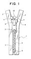
- This slide fastener is a well-known slide fastener.
- fastener elements 3, upper stoppers 4 and a lower stopper 5 are integrally molded along side edges of a fastener tape 2 using thermoplastic resin such as polyacetal, polyamide, polypropylene, polybutylene terephthalate or the like, by injection molding means so as to produce a slide fastener.
- the fastener element may be zigzag-type linear fastener element of synthetic resin monofilament or a single metallic unit.
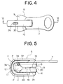
- a U-shaped guide lever 10 In a known reversible pull rotated type slider 6, as shown in Figs. 4 to 6, in order to form a pull 7 such that it may round from a top face to a front face and a bottom face of a body 9, in which an upper plate 15 and a lower plate 16 are connected through a diamond 17, a U-shaped guide lever 10 entirely presenting a U-letter is mounted on the body 9.
- the U-shaped guide lever 10 is mounted so as to surround a mounting post 22 erected at a rear mouth of the upper plate 15 and the lower plate 16 of the body 9 in a condition that the U-shaped guide lever 10 is capable of moving slightly back and forth. Consequently, the U-shaped guide lever 10 is moved by pulling the pull 7 in a back-and-forth direction.
- a concave portion 21 is provided in a front face of the diamond 17 of the body 9 so as to accommodate a hook piece 31 of a locking lever 28. Further, an insertion hole 24 is provided laterally in a middle of the diamond 17 and a spring 33 is fitted therein in order to press the hook piece 31 of the locking lever 28.
- a pawl hole 23 is made near the rear mouth of the upper plate 15 of the body 9 and a locking pawl 29 of the locking lever 28 is fitted therein. The locking pawl 29 is capable of moving into/from a guide groove 20 in the fastener element 3.
- the body 9 and U-shaped guide lever 10 are formed separately by die-casting using metal such as aluminum alloy, zinc alloy or the like, and the pull 7 is produced by pressing a metallic plate. After that, the pull rotated type slider 6 is assembled.
- An inner face of the U-shaped guide lever 10 is formed with T-shaped cross section.
- a center of the T-shaped pull guide portion 11 is protruded inward so as to form a cam 25 and a concave groove 13 is provided in a center of each of the pull guide portions 11 of an upper piece 37 and a lower piece 38.
- the top portion of the locking lever 28 supported by the body 9 is fitted into the concave groove 13 of the upper piece 37 while a convex row 19 protruded on a surface of the lower plate 16 of the body 9 is fitted into the concave groove 13 of the lower piece 38.
- the locking lever 28 is entirely formed in substantially elongated inverted-U shape and provided with the locking pawl 29 at one end and the hook piece 31 which is longer than the locking pawl 29 at the other end thereof.
- a pin hole 32 is provided in a base portion of the hook piece 31 so as to support the locking lever 28 on the body 9 with a pin 34 such that it can swing freely.
- a protruded piece 30 is provided protrudedly on an upper side of the hook piece 31 and this protruded piece 30 is fitted into an elongated hole 26 provided in the U-shaped guide lever 10 thereby restricting the swing of the locking lever 28 in the back-and-forth direction.
- the pull rotated type slider 6 If the pull rotated type slider 6 is slid in the opening direction, the U-shaped guide lever 10 is moved toward the rear mouth by pulling the pull 7, and at the same time, the hook piece 31 presses and pressurizes the spring 33 by a cam 25 so as to make the locking pawl 29 float from the guide groove 20. Consequently, the pull rotated type slider 6 can be slid.
- the pull rotated type slider is operated as described above.
- the feature of the slide fastener of the invention is provision of a start mechanism, which allows the pull rotated type slider 6 to start smoothly in the opening direction of the fastener chain 1 when the slide fastener is used in a mode that ends of the fastener tape 2 are closed as shown in Fig. 3.
- a front end of the upper stopper 4 mounted on the fastener chain 1 comes into contact with a corner of the pull guide portion 11 in the U-shaped guide lever 10 disposed in the pull rotated type slider 6. Consequently, the sliding of the pull rotated type slider 6 is blocked and the starting of the slider becomes difficult.
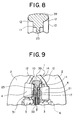
- an inclined face at an inner edge portion of the pull guide portion 11 in the front piece 39, except for the upper piece 37 and the lower piece 38, in the U-shaped guide lever 10 provided on the periphery of the body 9 is cut out as shown in Figs. 7 and 9 so as to form the guide face 12 for the upper stopper.
- the pull guide portion 11 of the U-shaped guide lever 10 is formed with T-shaped cross section and the inner edge portion of this pull guide portion 11 is formed into an inclined face so as to provide the guide face 12.
- a holding face 14 for holding the pull 7 in the horizontal condition, which comes into sliding contact with a front end of each L-shaped attaching piece 8 formed in the pull 7, is formed at a base end of the guide face 12, thereby holding the pull 7 securely and preventing the pull 7 from escaping from the U-shaped guide lever 10 in advance.
- the guide face 12, which is an inclined face in Fig. 7, may be an arc face as shown in Fig. 8.
- This arch-shaped guide face 12 is formed such that it is expanded gradually from an end portion of the upper piece 37 or lower piece 38 toward the front piece 39.
- the pull rotated type slider 6 can be started smoothly.
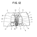
- the guide face 12 for the upper stopper 4 is formed by cutting out an inner edge portion of the pull guide portion 11 in the front piece 39 of the U-shaped guide lever 10, as shown in Fig. 11, so as to define an inclined face or an arc face.
- a guide portion 35 for the U-shaped guide lever 10 is formed by cutting out the corner which the pull guide portion 11 of the U-shaped guide lever 10 in the pull rotated type slider 6 comes into contact with, in the upper stopper 4 mounted on the fastener chain 1. Consequently, the pull rotated type slider 6 can be started smoothly by a sliding contact between this guide face 12 and the guide portion 35.
- the upper piece 37, the lower piece 38 and the front piece 39 of the U-shaped guide lever 10 in the pull rotated type slider 6 are formed in a conventional configuration with a inner face formed at right angle.
- the corner which the pull guide portion 11 of the U-shaped guide lever 10 comes into contact with, of the upper stopper 4 mounted on the fastener chain 1 is cut out in a wide inclined face or an arc face protruded outward from the outside edge of the pull guide portion 11 so as to form the guide portion 35 for the U-shaped guide lever 10. Consequently, the pull rotated type slider 6 can be started smoothly.
- the slide fastener of the invention has various kinds of the start mechanisms. Therefore, of course, the conventional use condition is available and even if end portions of the fastener chain 1 are closed upon usage as shown in Fig. 3, the pull rotated type slider 6 can be started smoothly and further, it can be changed to a reversible slide fastener easily.
Applications Claiming Priority (2)
| Application Number | Priority Date | Filing Date | Title |
|---|---|---|---|
| JP2001291542A JP3733309B2 (ja) | 2001-09-25 | 2001-09-25 | スライドファスナー用スライダー |
| JP2001291542 | 2001-09-25 |
Publications (3)
| Publication Number | Publication Date |
|---|---|
| EP1295542A2 true EP1295542A2 (de) | 2003-03-26 |
| EP1295542A3 EP1295542A3 (de) | 2006-11-22 |
| EP1295542B1 EP1295542B1 (de) | 2014-04-30 |
Family
ID=19113670
Family Applications (1)
| Application Number | Title | Priority Date | Filing Date |
|---|---|---|---|
| EP02019973.3A Expired - Lifetime EP1295542B1 (de) | 2001-09-25 | 2002-09-05 | Schieber für Reissverschluss |
Country Status (8)
| Country | Link |
|---|---|
| US (1) | US20030056342A1 (de) |
| EP (1) | EP1295542B1 (de) |
| JP (1) | JP3733309B2 (de) |
| KR (1) | KR100478643B1 (de) |
| CN (1) | CN1251630C (de) |
| ES (1) | ES2462533T3 (de) |
| HK (1) | HK1061336A1 (de) |
| TW (1) | TW589163B (de) |
Cited By (4)
| Publication number | Priority date | Publication date | Assignee | Title |
|---|---|---|---|---|
| US6735827B1 (en) * | 2002-12-23 | 2004-05-18 | Stenhaell Turo | Slider for a zip fastener |
| CN101554258B (zh) * | 2008-03-13 | 2012-04-18 | 锐力股份有限公司 | 拉链以及用于拉链的上止 |
| EP1972225A3 (de) * | 2007-03-20 | 2014-03-26 | YKK Corporation | Schieber für doppelseitigen Reißverschluss mit automatischer Sperrvorrichtung |
| US9232834B2 (en) | 2010-09-24 | 2016-01-12 | Ykk Corporation | Slider for slide fastener with automatic stopper |
Families Citing this family (8)
| Publication number | Priority date | Publication date | Assignee | Title |
|---|---|---|---|---|
| US8122573B2 (en) * | 2009-01-07 | 2012-02-28 | Ykk Corporation | Thin slider |
| US8484764B2 (en) | 2010-08-18 | 2013-07-16 | Under Armour, Inc. | Zipper arrangement |
| US9072347B2 (en) * | 2010-09-06 | 2015-07-07 | Ykk Corporation | Slide fastener and slider for slide fastener |
| US8341809B2 (en) | 2010-11-16 | 2013-01-01 | Under Armour, Inc. | Zipper arrangement with funnel grip |
| US8484811B2 (en) | 2010-11-16 | 2013-07-16 | Under Armour, Inc. | Zipper arrangement with wheeled slider |
| US8528115B2 (en) | 2010-11-16 | 2013-09-10 | Under Armour, Inc. | Zipper arrangement with foldable pull |
| WO2012177003A2 (ko) * | 2011-06-21 | 2012-12-27 | Jung Ji Ong | 슬라이드 파스너용 자동 잠김 슬라이더 |
| US10575601B2 (en) | 2015-10-02 | 2020-03-03 | Under Armour, Inc. | Stop for zipper arrangement |
Citations (3)
| Publication number | Priority date | Publication date | Assignee | Title |
|---|---|---|---|---|
| US1302606A (en) | 1917-06-20 | 1919-05-06 | Hookless Fastener Co | Separable fastener-slider. |
| US2894305A (en) | 1956-05-08 | 1959-07-14 | Talon Inc | Quick release end stop |
| DE1164721B (de) | 1964-03-05 | Postel Geb | Von zwei Seiten zu betaetigender Reissverschlussschieber |
Family Cites Families (6)
| Publication number | Priority date | Publication date | Assignee | Title |
|---|---|---|---|---|
| US1966255A (en) * | 1926-09-22 | 1934-07-10 | Marinsky Davis | Coupling and locking means for fastening devices |
| CH404271A (de) * | 1963-07-25 | 1965-12-15 | Giumen Anstalt | Schieber für Reissverschluss |
| DE2503281C3 (de) * | 1974-02-08 | 1980-08-14 | Aisin Seiki K.K., Kariya, Aichi (Japan) | Innenverriegelungsvorrichtung mit einer zusätzlichen Betätigimgsstellung des Innenverriegelungsknopf es zum schlüssellosen Verriegeln eines Kfz-Türverschlusses |
| JPS611770Y2 (de) * | 1981-03-06 | 1986-01-21 | ||
| JPS6232416Y2 (de) * | 1981-04-09 | 1987-08-19 | ||
| JPS60145105A (ja) * | 1983-12-31 | 1985-07-31 | ワイケイケイ株式会社 | 自動停止装置付スライダ−を具備する開離嵌插具付スライドフアスナ− |
-
2001
- 2001-09-25 JP JP2001291542A patent/JP3733309B2/ja not_active Expired - Lifetime
-
2002
- 2002-08-27 TW TW091119427A patent/TW589163B/zh not_active IP Right Cessation
- 2002-08-28 US US10/229,165 patent/US20030056342A1/en not_active Abandoned
- 2002-09-05 ES ES02019973.3T patent/ES2462533T3/es not_active Expired - Lifetime
- 2002-09-05 EP EP02019973.3A patent/EP1295542B1/de not_active Expired - Lifetime
- 2002-09-13 KR KR10-2002-0055751A patent/KR100478643B1/ko active IP Right Grant
- 2002-09-24 CN CNB021323364A patent/CN1251630C/zh not_active Expired - Lifetime
-
2003
- 2003-05-19 HK HK03103518A patent/HK1061336A1/xx not_active IP Right Cessation
Patent Citations (3)
| Publication number | Priority date | Publication date | Assignee | Title |
|---|---|---|---|---|
| DE1164721B (de) | 1964-03-05 | Postel Geb | Von zwei Seiten zu betaetigender Reissverschlussschieber | |
| US1302606A (en) | 1917-06-20 | 1919-05-06 | Hookless Fastener Co | Separable fastener-slider. |
| US2894305A (en) | 1956-05-08 | 1959-07-14 | Talon Inc | Quick release end stop |
Cited By (4)
| Publication number | Priority date | Publication date | Assignee | Title |
|---|---|---|---|---|
| US6735827B1 (en) * | 2002-12-23 | 2004-05-18 | Stenhaell Turo | Slider for a zip fastener |
| EP1972225A3 (de) * | 2007-03-20 | 2014-03-26 | YKK Corporation | Schieber für doppelseitigen Reißverschluss mit automatischer Sperrvorrichtung |
| CN101554258B (zh) * | 2008-03-13 | 2012-04-18 | 锐力股份有限公司 | 拉链以及用于拉链的上止 |
| US9232834B2 (en) | 2010-09-24 | 2016-01-12 | Ykk Corporation | Slider for slide fastener with automatic stopper |
Also Published As
| Publication number | Publication date |
|---|---|
| CN1410017A (zh) | 2003-04-16 |
| KR100478643B1 (ko) | 2005-03-28 |
| US20030056342A1 (en) | 2003-03-27 |
| TW589163B (en) | 2004-06-01 |
| KR20030026851A (ko) | 2003-04-03 |
| EP1295542A3 (de) | 2006-11-22 |
| JP2003093116A (ja) | 2003-04-02 |
| ES2462533T3 (es) | 2014-05-23 |
| JP3733309B2 (ja) | 2006-01-11 |
| EP1295542B1 (de) | 2014-04-30 |
| HK1061336A1 (en) | 2004-09-17 |
| CN1251630C (zh) | 2006-04-19 |
Similar Documents
| Publication | Publication Date | Title |
|---|---|---|
| EP1972225B1 (de) | Schieber für doppelseitigen Reißverschluss mit automatischer Sperrvorrichtung | |
| EP1776889B1 (de) | Reissverschlussschieber mit Verriegelungsvorrichtung | |
| JP3733311B2 (ja) | スライドファスナー用スライダーの引手 | |
| US6634066B2 (en) | Upper stopper device for slide fastener | |
| EP1762153B1 (de) | Reissverschluss-Schieber mit einer automatischen Verriegelungsvorrichtung | |
| EP1295542B1 (de) | Schieber für Reissverschluss | |
| US6615458B2 (en) | Releasable bottom end stop for slide fastener | |
| US7111367B2 (en) | Slider for a concealed slide fastener | |
| KR19980087091A (ko) | 슬라이드 파스너용 슬라이더 | |
| KR101255929B1 (ko) | 개방 분리 끼움 삽입구가 부착된 슬라이드 파스너 | |
| CA2176657C (en) | Automatic lock slider for slide fastener | |
| US9254020B2 (en) | Slide fastener slider | |
| EP0839466B1 (de) | Automatisch verriegelbarer Schieber für einen Reissverschluss | |
| CN101980627B (zh) | 拉链用开口部件 | |
| EP0868862B1 (de) | Schieber für Reissverschlüsse mit automatischer Verriegelungsvorrichtung | |
| CN112040807A (zh) | 拉链用拉头 | |
| TW202007301A (zh) | 拉鏈用滑件 | |
| JPH08173215A (ja) | 開離嵌挿具付きのスライドファスナー |
Legal Events
| Date | Code | Title | Description |
|---|---|---|---|
| PUAI | Public reference made under article 153(3) epc to a published international application that has entered the european phase |
Free format text: ORIGINAL CODE: 0009012 |
|
| AK | Designated contracting states |
Kind code of ref document: A2 Designated state(s): AT BE BG CH CY CZ DE DK EE ES FI FR GB GR IE IT LI LU MC NL PT SE SK TR Designated state(s): AT BE BG CH CY CZ DE DK EE ES FI FR GB GR IE IT LI LU MC NL PT SE SK TR |
|
| AX | Request for extension of the european patent |
Extension state: AL LT LV MK RO SI |
|
| PUAL | Search report despatched |
Free format text: ORIGINAL CODE: 0009013 |
|
| AK | Designated contracting states |
Kind code of ref document: A3 Designated state(s): AT BE BG CH CY CZ DE DK EE ES FI FR GB GR IE IT LI LU MC NL PT SE SK TR |
|
| AX | Request for extension of the european patent |
Extension state: AL LT LV MK RO SI |
|
| 17P | Request for examination filed |
Effective date: 20070301 |
|
| 17Q | First examination report despatched |
Effective date: 20070412 |
|
| AKX | Designation fees paid |
Designated state(s): DE ES FR GB IT |
|
| GRAP | Despatch of communication of intention to grant a patent |
Free format text: ORIGINAL CODE: EPIDOSNIGR1 |
|
| INTG | Intention to grant announced |
Effective date: 20140204 |
|
| GRAS | Grant fee paid |
Free format text: ORIGINAL CODE: EPIDOSNIGR3 |
|
| GRAA | (expected) grant |
Free format text: ORIGINAL CODE: 0009210 |
|
| AK | Designated contracting states |
Kind code of ref document: B1 Designated state(s): DE ES FR GB IT |
|
| REG | Reference to a national code |
Ref country code: GB Ref legal event code: FG4D |
|
| REG | Reference to a national code |
Ref country code: ES Ref legal event code: FG2A Ref document number: 2462533 Country of ref document: ES Kind code of ref document: T3 Effective date: 20140523 |
|
| REG | Reference to a national code |
Ref country code: DE Ref legal event code: R096 Ref document number: 60246231 Country of ref document: DE Effective date: 20140612 |
|
| REG | Reference to a national code |
Ref country code: DE Ref legal event code: R097 Ref document number: 60246231 Country of ref document: DE |
|
| PLBE | No opposition filed within time limit |
Free format text: ORIGINAL CODE: 0009261 |
|
| STAA | Information on the status of an ep patent application or granted ep patent |
Free format text: STATUS: NO OPPOSITION FILED WITHIN TIME LIMIT |
|
| 26N | No opposition filed |
Effective date: 20150202 |
|
| REG | Reference to a national code |
Ref country code: DE Ref legal event code: R097 Ref document number: 60246231 Country of ref document: DE Effective date: 20150202 |
|
| REG | Reference to a national code |
Ref country code: FR Ref legal event code: PLFP Year of fee payment: 15 |
|
| REG | Reference to a national code |
Ref country code: FR Ref legal event code: PLFP Year of fee payment: 16 |
|
| REG | Reference to a national code |
Ref country code: FR Ref legal event code: PLFP Year of fee payment: 17 |
|
| PGFP | Annual fee paid to national office [announced via postgrant information from national office to epo] |
Ref country code: IT Payment date: 20190917 Year of fee payment: 18 Ref country code: FR Payment date: 20190815 Year of fee payment: 18 |
|
| PGFP | Annual fee paid to national office [announced via postgrant information from national office to epo] |
Ref country code: GB Payment date: 20190905 Year of fee payment: 18 |
|
| PGFP | Annual fee paid to national office [announced via postgrant information from national office to epo] |
Ref country code: ES Payment date: 20191002 Year of fee payment: 18 |
|
| GBPC | Gb: european patent ceased through non-payment of renewal fee |
Effective date: 20200905 |
|
| PG25 | Lapsed in a contracting state [announced via postgrant information from national office to epo] |
Ref country code: FR Free format text: LAPSE BECAUSE OF NON-PAYMENT OF DUE FEES Effective date: 20200930 |
|
| PG25 | Lapsed in a contracting state [announced via postgrant information from national office to epo] |
Ref country code: GB Free format text: LAPSE BECAUSE OF NON-PAYMENT OF DUE FEES Effective date: 20200905 |
|
| PG25 | Lapsed in a contracting state [announced via postgrant information from national office to epo] |
Ref country code: IT Free format text: LAPSE BECAUSE OF NON-PAYMENT OF DUE FEES Effective date: 20200905 |
|
| PGFP | Annual fee paid to national office [announced via postgrant information from national office to epo] |
Ref country code: DE Payment date: 20210727 Year of fee payment: 20 |
|
| REG | Reference to a national code |
Ref country code: ES Ref legal event code: FD2A Effective date: 20220114 |
|
| PG25 | Lapsed in a contracting state [announced via postgrant information from national office to epo] |
Ref country code: ES Free format text: LAPSE BECAUSE OF NON-PAYMENT OF DUE FEES Effective date: 20200906 |
|
| REG | Reference to a national code |
Ref country code: DE Ref legal event code: R071 Ref document number: 60246231 Country of ref document: DE |