EP1293799A2 - Verfahren zur Erfassung einer Luftlage in einem Kampffahrzeug sowie Vorrichtung zur Durchführung des Verfahrens - Google Patents
Verfahren zur Erfassung einer Luftlage in einem Kampffahrzeug sowie Vorrichtung zur Durchführung des Verfahrens Download PDFInfo
- Publication number
- EP1293799A2 EP1293799A2 EP02020218A EP02020218A EP1293799A2 EP 1293799 A2 EP1293799 A2 EP 1293799A2 EP 02020218 A EP02020218 A EP 02020218A EP 02020218 A EP02020218 A EP 02020218A EP 1293799 A2 EP1293799 A2 EP 1293799A2
- Authority
- EP
- European Patent Office
- Prior art keywords
- target
- measured values
- data
- pulses
- target echo
- Prior art date
- Legal status (The legal status is an assumption and is not a legal conclusion. Google has not performed a legal analysis and makes no representation as to the accuracy of the status listed.)
- Granted
Links
Images


Classifications
-
- G—PHYSICS
- G01—MEASURING; TESTING
- G01S—RADIO DIRECTION-FINDING; RADIO NAVIGATION; DETERMINING DISTANCE OR VELOCITY BY USE OF RADIO WAVES; LOCATING OR PRESENCE-DETECTING BY USE OF THE REFLECTION OR RERADIATION OF RADIO WAVES; ANALOGOUS ARRANGEMENTS USING OTHER WAVES
- G01S13/00—Systems using the reflection or reradiation of radio waves, e.g. radar systems; Analogous systems using reflection or reradiation of waves whose nature or wavelength is irrelevant or unspecified
- G01S13/66—Radar-tracking systems; Analogous systems
- G01S13/72—Radar-tracking systems; Analogous systems for two-dimensional [2D] tracking, e.g. combination of angle and range tracking, track-while-scan radar
- G01S13/723—Radar-tracking systems; Analogous systems for two-dimensional [2D] tracking, e.g. combination of angle and range tracking, track-while-scan radar by using numerical data
-
- F—MECHANICAL ENGINEERING; LIGHTING; HEATING; WEAPONS; BLASTING
- F41—WEAPONS
- F41G—WEAPON SIGHTS; AIMING
- F41G5/00—Elevating or traversing control systems for guns
- F41G5/08—Ground-based tracking-systems for aerial targets
Definitions
- the invention relates to a method for detecting an air position in one Combat vehicle equipped with a search radar device, the one Transmitter / receiver with rotating transmit / receive antenna, a signal evaluation device as well as a viewing device, with the transmission / reception antenna per revolution Target echo signals are generated for optical display serve the targets using a Braun tube.
- Such search radar devices are generally known and can for example installed in a combat vehicle equipped for air defense his.
- the invention has for its object a method and a device to create the data acquisition, generation and deployment an air situation in a combat vehicle and the transfer of the Data from a combat vehicle over a radio link to an outside this combat vehicle arranged computer to represent a "foreign air situation" enable.
- the search radar emitted target echo signals initially only for a special Are intended and suitable for the purpose, namely for the optical representation on a Braun tube and not to calculate numerical values of the Target coordinates. So there was first the task for another Purpose to process signals so that they can be used to calculate the numerical values the target coordinates are suitable. Then this calculation had to be done be carried out and the determined target coordinates should be in a form exist that they can be transmitted further.
- the basic idea of the invention is the pulses of the target echo signals tap, process in rectangular pulses and the distances of the Measure target pulses from the clock pulse and the length of the target pulses and digitize.
- this method initially encounters difficulties in the Evaluation and transfer of the data because of an extraordinarily high amount of data should be evaluated per unit of time.
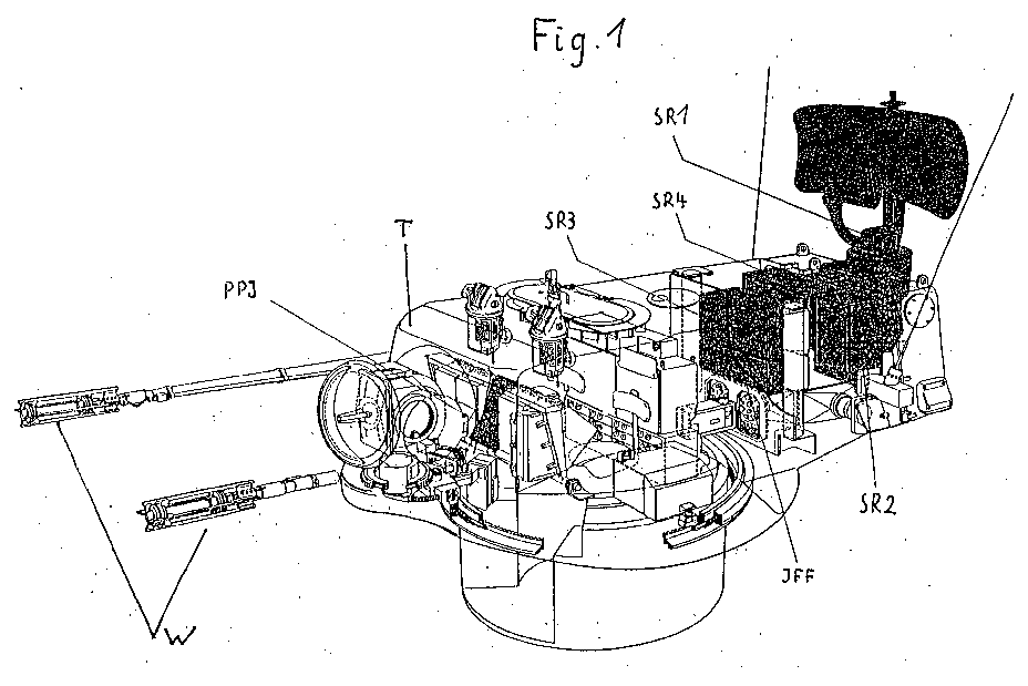
- Fig. 1 shows the tower T rotatable in azimuth one not otherwise shown Anti-aircraft gun tank with a weapon system W and the individual Components of a search radar device, namely a rotating one SR / IFF antenna with drive and lifting hydraulics SR1, a search radar transmitter SR2, a search radar receiver SR3 and a power supply SR4.
- a search radar device namely a rotating one SR / IFF antenna with drive and lifting hydraulics SR1, a search radar transmitter SR2, a search radar receiver SR3 and a power supply SR4.
- the facility has an IFF interrogator for identification Friend / enemy and in the front part of the tower T a PPI display device for display the air situation on a Braun tube.
- FIG. 1A shows an operating device and the electronics SR'-IFF 'with one Viewing device PPI ', which is within the combat vehicle shown in Fig. 1 are arranged to be there by the search radar device of the combat vehicle 1 shown air position to display.
- FIG. 1B shows a schematic block diagram of those shown in FIG. 1
- the simplified Receiving part of the search radar device is designated SR.
- Receiving part SR are clock pulses, target pulses (target data) and pulses For identification of friend / enemy (IFF data) fed to the PPI viewing device PPI.
- the clock pulses are generated by means of a first data acquisition device D1 and the target pulses of the target echo signals are tapped and in below explained in the form of rectangular pulses and processed. The obtained and reduced in their amount also explained below Data is transferred to a CAN bus CAN and from there to one Computer supplied to calculate and display the goals.
- a second data acquisition device D2, shown in dashed lines in FIG. 1B works in an analogous manner to the data acquisition device D1 and is used for tapping and processing the signals of identification Friend / enemy.
- FIG. 2 shows the basic structure in an exemplary and simplified manner of the signals used to record the air position, namely a synchronization or clock pulse T and a target pulse Z.
- the time interval of the target pulse Z from the clock pulse T characterizes the distance of the target, while the temporal length of the target pulse Z is the length of the target characterized.
- Fig. 2 shows a target echo signal in a simplified form. This Target echo signal corresponds to a radar beam.
- the transmit / receive antenna SR1 the search radar device rotates at 1 Hz and transmits approx. 7000 radar beams, i.e. 7000 target echo signals per revolution. If the tower T stands, these 7000 target echo signals correspond to a field of view of 360 °. This is shown in a diagram in FIG. 3.
- the target echo signals ZE are included numbered from 0 to 6999.
- FIG. 4 shows the data acquisition device in a somewhat more detailed block diagram D1, which is designed as a single-chip CPU with a CPU 1, one Time processor unit (TPU) 2, the latter counter modules (CNT) 3.1, 3.2, 3.3 and 3.4 contains.
- the CAN bus 4 and memory units are also located on it 5th
- a unit E with a is connected upstream of the data acquisition device D1 Filter 6 for the incoming target pulses.
- the filter 6 is used for cleaning disturbed input signals so that unnecessarily many pulses are not measured have to. This is necessary because the target echo signal is not always is in pure form. It can be disturbed by, for example, several Targets lie one after the other on a ray and targets with different ones can be Length.
- the operation of the filter 6 is as follows. With each "high" value of the input signal a retriggerable counter becomes set. The counter counts down from the set value to zero and is set so that this process a fixed predetermined period of time, for example 5 ⁇ s. This extends each input pulse by 5 ⁇ s. These 5 ⁇ s will be subtracted later after the measurement to the exact length to get the goal.
- the individual target pulses of each target echo signal are generated by the distributor 7 distributes the channels leading to the counter modules 3.1 to 3.4 in such a way that the first counter module 3.1 only the first target pulse, the second counter module 3.2 only has to measure the second target pulse etc.
- the exemplary embodiment is the distribution over four counter modules 3.1 to 3.4 shown. In practice, of course, a higher number of counter modules be provided. 5 shows, both the clock pulses T as well as the target pulses Z1, Z2, Z3, which are emitted by the filter 6, Rectangular pulses, which are shown as arrows in the lower part of FIG. 5 Trigger interrupts that can be processed correctly by the TPU 2.
- the data determined should be transferred from the data acquisition device D1 to the PC a CAN bus because this bus is a fast, interference-free and proven transmission medium.
- Data acquisition would be the retransmission for processing the so as already mentioned at the beginning, with considerable amounts of data Difficulties connected because there is too much data. It is therefore necessary to reduce the amount of data.
- the measured values are mapped to the range of data, which are then represented by a bit in the data telegram. This is shown schematically in Fig. 6. In the one shown in Fig. 6 from 8 bytes Existing data telegram, for example, the 5th bit in the 1st byte Distance range from 500 to 599m.
- FIG. 7 represent the successive Target echo signals, referred to as "beam 3502", etc., measurements of the same target. From beam 3556 another signal comes from a second Target.
- beam 3502 the successive Target echo signals
- the measured values of the target data of a beam are not identical.
- the readings concern the same goal. Therefore all measured values should be transmitted become, which would ultimately not lead to a real reduction. Therefore, the measured values are first mapped on a grid. It will not the measured values, but the screened measured values.
- the Rays 3502 and 3503 are now falling, for example, despite different measured values, namely 83 ⁇ s and 86 ⁇ s compared to 84 ⁇ s and 87 ⁇ s in the same grid.
- the values to be transferred are identical and only one value is required be transmitted.
- the screened measured values correspond to the respective Range areas are assigned with each target echo signal the corresponding measured values of the previous target echo signal be compared and data will only be transferred if have changed the screened measured values.
- the measured values have not changed over a longer period of time, can include additional data telegrams for synchronization in the transmission be inserted.
- To assign the data telegrams to the individual Target echo signals are still the number of identical in the telegrams Transmit target echo signals. This allows the exact "beam number" for each Data telegram can be calculated.
- the successive target echo signals can also in Be disturbed in relation to the angular range. So especially at the beginning and at the end of a target, entire target echo signals also disappear. this leads to to target representations, as are shown, for example, in FIG. 8.
- Fig. 8 3 shows the total angular range detected by the search radar, in a diagram analogous to FIG. being from a certain angular range, the "disturbed Target "is called, disturbed target echo signals come to a representation of the target, as it is shown in Fig. 8, slightly enlarged Area corresponds. Holes can be seen at the beginning and end of the target.
- the angle range is “shading” of 180 °, which depends on the respective position of the Turret of the combat vehicle facing away from the direction of the weapon system is.
- the end of the target is transmitted and thus each target is three beams wider in the illustrated embodiment than it actually is.
- This constant error is compensated for by: the transmission is subtracted before the evaluation.
- Fig. 10 shows as Example the result of such a calculation.
- the location of the center of gravity is displayed as the target coordinate with target angle and target distance and can be logged.
- This target coordinate can then also be simple Transfer serial connections with low data rate to external systems become.
- a test target (Fig. 11B) is first detected.
- the test target is always exactly in the north and is on the target echo signal shown as the only target in the extreme range. That in the diagram 11A can then according to FIG. 11 by a Block appear on the screen.
- the angle reference of the individual Blasting is based on the test target.
- the angle of that shown in Fig. 11 Block results from the ray number and the angle reference and the The position of the start point and end point of the block is transferred based on the Distance coordinates calculated.
- the procedure described so far for the acquisition and processing of the target data can also be used to capture the signals of friend / foe marking (IFF) can be used.
- the IFF data is recorded and evaluated by means of a one designated by D2 in FIG. 1B and shown in broken lines Data acquisition device, which is also designed as a single-chip CPU can.
- D2 friend / foe marking
- Data acquisition device which is also designed as a single-chip CPU can.
- the data is compressed and simultaneously transmitted to the evaluation computer via the CAN bus.
- 12 and 13 are exemplary measured values of a target with the IFF identifier activated "Friend" represented.
- the target data is typically on other beams than the IFF data and the distance of the target data and the IFF data is different.
- the IFF signal is at the same time with a small offset Target echo signal and has the same temporal characteristic, but is not with every radar beam, but typically only transmitted with every 16th beam.
- FIG. 14 illustrates an extension of the device shown in FIG. 1B which can be seen, such as those captured in an anti-aircraft tank 1 and data processed for the air situation via a radio data link DF from Transfer anti-aircraft tank 1 to a receiving device EE in anti-aircraft tank 2 are displayed there on the PPI display device PPI 'as external air become.
- 15 and 16 show an example of a result of the illustrated Process. Target flights were simulated in different series of measurements and the determined flight data logged. 15 shows in an angle / distance diagram an actual trajectory of a search radar Flying object. 16 shows in the same representation that due to the above explained method detected and calculated trajectory. It has been shown that the detection of the angle values is, as expected, very precise, while the accuracy of the distance measurement is not quite as great because the resolution of the search radar is limited in the range.
Landscapes
- Engineering & Computer Science (AREA)
- Radar, Positioning & Navigation (AREA)
- Remote Sensing (AREA)
- General Engineering & Computer Science (AREA)
- Computer Networks & Wireless Communication (AREA)
- Physics & Mathematics (AREA)
- General Physics & Mathematics (AREA)
- Radar Systems Or Details Thereof (AREA)
Abstract
Description
Claims (17)
- Verfahren zur Erfassung einer Luftlage in einem Kampffahrzeug, das mit einer Suchradareinrichtung ausgerüstet ist, die einen Sender/Empfänger mit rotierender Sende/Empfangsantenne, eine Signalauswerteeinrichtung sowie ein Sichtgerät umfaßt, wobei pro Umdrehung der Sende/Empfangsantenne Zielechosignale erzeugt werden, die zur optischen Darstellung der Ziele mittels einer Braunschen Röhre dienen, gekennzeichnet durch folgende Verfahrensschritte:a) die Impulse der Zielechosignale werden abgegriffen und zu Rechteckimpulsen verarbeitet, wobei der zeitliche Abstand jedes Zielimpulses von einem Taktimpuls die Zielentfernung und die zeitliche Länge des Zielimpulses die Ziellänge charakterisiert;b) die Abstände der Zielimpulse vom Taktimpuls sowie die Länge der Zielimpulse werden vermessen, digitalisiert und die digitalisierten Meßwerte werden auf ein vorgegebene Entfernungsbereiche enthaltendes Raster abgebildet;c) die den Entfernungsbereichen zugeordneten gerasterten Meßwerte jedes Zielechosignals werden mit den Meßwerten der entsprechenden Entfernungsbereiche von mindestens einem der jeweils vorhergehenden Zielechosignals verglichen und die Daten werden nur weiter übertragen, wenn sich die Meßwerte geändert haben;d) die so reduzierten Daten sowie die Anzahl der identischen Zielechosignale werden zur Berechnung und Anzeige der Zahlenwerte der Zielkoordinaten verwendet;e) die Zahlenwerte der Zielkoordinaten werden als Fremdluftlage an andere Waffensysteme übertragen und/oder im eigenen Waffensystem als Luftlage verwendet.
- Verfahren nach Anspruch 1, dadurch gekennzeichnet, daß die Vermessung der Abstände der Zielimpulse vom Taktimpuls und der Länge der Zielimpulse mittels Zählermodulen erfolgt.
- Verfahren nach Anspruch 1 oder 2, dadurch gekennzeichnet, daß aus den gerasterten Meßwerten ein Datentelegramm erzeugt wird, wobei jeder Entfernungsbereich im Datentelegramm durch ein Bit dargestellt wird.
- Verfahren nach Anspruch 3, dadurch gekennzeichnet, daß die Datentelegramme über einen CAN-Bus auf einen Rechner übertragen werden.
- Verfahren nach Anspruch 3 oder 4, dadurch gekennzeichnet, daß zusätzliche Datentelegramme zur Synchronisation in die Übertragung eingefügt werden, wenn sich die Meßwerte über einen vorgegebenen längeren Zeitraum nicht geändert haben.
- Verfahren nach einem der Ansprüche 1 bis 5, dadurch gekennzeichnet, daß die Zielimpulse der Zielechosignale vor der Verarbeitung zur Bereinigung gestörter Signale einem Filterverfahren unterworfen werden.
- Verfahren nach Anspruch 6 gekennzeichnet durch ein Filterverfahren, bei dem mit jedem "High"-Wert des Zielechosignals ein retriggerbarer Zähler gesetzt wird, der vom gesetzten Wert bis 0 zählt und derart eingestellt ist, daß der Zählvorgang eine fest vorgegebene Zeitdauer besitzt, die nach der Vermessung der Zielimpulse wieder vom gemessenen Wert abgezogen wird zur exakten Ermittlung der Länge des Ziels.
- Verfahren nach einem der Ansprüche 1 bis 7 gekennzeichnet durch eine Unterdrückung von Störungen im Winkelbereich, indem beim Vergleich der Meßwerte eines Zielechosignals mit den Meßwerten des jeweils vorhergehenden Zielechosignals jeweils die Meßwerte einer vorgegebenen Anzahl aufeinanderfolgender vorhergehender Zielechosignale durch logisch "ODER" miteinander verknüpft werden und eine hierdurch gegebenenfalls zu breite Zieldarstellung nach der Übertragung vor der Auswertung korrigiert wird.
- Verfahren nach einem der Ansprüche 1 bis 8, dadurch gekennzeichnet, daß aus den übertragenen Daten, nämlich den Nummern der Zielechosignale und den den Entfernungsbereichen zugeordneten Meßwerten zusammenhängende Entfernungsbereiche bestimmt und deren geometrischer Schwerpunkt berechnet und die Lage dieses Schwerpunktes als Zielkoordinaten mit Zielwinkel und Zielentfernung angezeigt werden.
- Verfahren nach einem der Ansprüche 1 bis 9, dadurch gekennzeichnet, daß die Zielkoordinaten über eine serielle Verbindungsstrecke an ein anderes internes System übertragen werden.
- Verfahren nach einem der Ansprüche 1 bis 9, dadurch gekennzeichnet, daß die Zielkoordinaten über eine Funkstrecke auf einen außerhalb des Kampffahrzeugs angeordneten Rechner übertragen werden.
- Verfahren nach Anspruch 10 oder 11, dadurch gekennzeichnet, daß die übertragenen Zielkoordinaten auf einem Bildschirm durch Blöcke dargestellt werden, wobei der Winkelbezug der einzelnen Zielechosignale anhand eines Prüfziels erfolgt, so daß sich der Winkel der Blöcke durch die Nummern des Zielechosignals und den Winkelbezug ergibt und die Lage der Anfangs- und Endkoordinaten der Blöcke aufgrund der übertragenen Meßwerte der Entfernungskoordinaten berechnet wird.
- Verfahren nach einem der Ansprüche 1 bis 12, dadurch gekennzeichnet, daß parallel zur Erfassung der Zieldaten in einer unabhängigen Anwendung des gleichen Verfahrens die Signale der Identifizierung-Freund-Feind (IFF) erfaßt und verarbeitet werden.
- Verfahren nach den Ansprüchen 9 und 13, dadurch gekennzeichnet, daß für die Meßergebnisse der Zielerfassung und die Meßergebnisse der IFF-Erfassung jeweils eine unabhängige Schwerpunktsbildung gemäß Anspruch 9 durchgeführt wird und wenn beide Schwerpunkte innerhalb eines vorgegebenen Toleranzbereiches liegen, das Ziel entsprechend dem Ergebnis der IFF-Erfassung gekennzeichnet wird.
- Vorrichtung zur Durchführung des Verfahrens nach einem der Ansprüche 1 bis 14 mit einer Suchradareinrichtung (SR) die einen Sender/Empfänger (SR2-SR3) mit rotierender Sende-Empfangsantenne (SR1) eine Signalauswerteeinrichtung sowie ein Sichtgerät (PPI) umfaßt, gekennzeichnet durch mindestens eine an die Übertragungsstrecke zwischen Signalauswerteeinrichtung und Sichtgerät angeschlossene Datenerfassungseinrichtung (D1) zur Erfassung der Taktimpulse und der Zielimpulse des Zielechosignals und gegebenenfalls des IFF-Signals, die eine CPU und eine TPU mit Zählermodulen (3.1 bis 3.4) enthält und an die über einen CAN-Bus (CAN) mindestens ein Rechner angeschlossen ist.
- Vorrichtung nach Anspruch 12, dadurch gekennzeichnet, daß die Zielechosignale der Datenerfassungseinrichtung (D1) über ein Filter (6) zur Bereinigung gestörter Signale zugeführt werden.
- Vorrichtung nach Anspruch 15 oder 16, dadurch gekennzeichnet, daß die zum gleichen Zielechosignal gehörenden Zielimpulse über ein Verteilermodul (7) unterschiedlichen Zählermodulen (3.1 bis 3.4) zugeführt werden.
Applications Claiming Priority (2)
| Application Number | Priority Date | Filing Date | Title |
|---|---|---|---|
| DE2001145641 DE10145641A1 (de) | 2001-09-15 | 2001-09-15 | Verfahren zur Erfassung einer Luftlage in einem Kampffahrzeug sowie Vorrichtung zur Durchführung des Verfahrens |
| DE10145641 | 2001-09-15 |
Publications (3)
| Publication Number | Publication Date |
|---|---|
| EP1293799A2 true EP1293799A2 (de) | 2003-03-19 |
| EP1293799A3 EP1293799A3 (de) | 2004-01-28 |
| EP1293799B1 EP1293799B1 (de) | 2005-10-26 |
Family
ID=7699231
Family Applications (1)
| Application Number | Title | Priority Date | Filing Date |
|---|---|---|---|
| EP20020020218 Expired - Lifetime EP1293799B1 (de) | 2001-09-15 | 2002-09-10 | Verfahren zur Erfassung einer Luftlage in einem Kampffahrzeug sowie Vorrichtung zur Durchführung des Verfahrens |
Country Status (2)
| Country | Link |
|---|---|
| EP (1) | EP1293799B1 (de) |
| DE (2) | DE10145641A1 (de) |
Cited By (3)
| Publication number | Priority date | Publication date | Assignee | Title |
|---|---|---|---|---|
| EP2131208A1 (de) * | 2008-06-03 | 2009-12-09 | Saab AB | Anzeigevorrichtung |
| WO2015052707A1 (en) | 2013-10-08 | 2015-04-16 | Israel Aerospace Industries Ltd. | Missile system including ads-b receiver |
| CN114859347A (zh) * | 2022-04-24 | 2022-08-05 | 苏州空天信息研究院 | 一种基于sar子视分析的海面自适应成像方法 |
Families Citing this family (2)
| Publication number | Priority date | Publication date | Assignee | Title |
|---|---|---|---|---|
| DE10246994B3 (de) | 2002-10-02 | 2004-05-13 | Sai Automotive Sal Gmbh | Stirnwandmodul |
| FR2875613B1 (fr) * | 2004-09-23 | 2007-03-16 | Giat Ind Sa | Interface homme machine d'un systeme de traitement de menaces |
Family Cites Families (6)
| Publication number | Priority date | Publication date | Assignee | Title |
|---|---|---|---|---|
| DE2828511C2 (de) * | 1978-06-29 | 1991-01-24 | Licentia Patent-Verwaltungs-Gmbh, 6000 Frankfurt | Zielextraktorsystem für eine Radaranlage |
| DE3665930D1 (en) * | 1985-07-04 | 1989-11-02 | Contraves Ag | Target measurement system |
| DE3533213C1 (en) * | 1985-09-18 | 1989-09-28 | Siemens Ag | Arrangement for displaying an airway corridor in the correct coordinates |
| ES2040736T3 (es) * | 1986-12-22 | 1993-11-01 | Oerlikon-Contraves Ag | Sistema de persecucion de blancos. |
| CH690199A5 (de) * | 1995-02-09 | 2000-05-31 | Contraves Ag | Zielverfolgungs-Einrichtung und Zielverfolgungs-Verfahren |
| NL9500285A (nl) * | 1995-02-16 | 1996-10-01 | Hollandse Signaalapparaten Bv | Vuurleidingssysteem. |
-
2001
- 2001-09-15 DE DE2001145641 patent/DE10145641A1/de not_active Withdrawn
-
2002
- 2002-09-10 DE DE50204667T patent/DE50204667D1/de not_active Expired - Lifetime
- 2002-09-10 EP EP20020020218 patent/EP1293799B1/de not_active Expired - Lifetime
Cited By (5)
| Publication number | Priority date | Publication date | Assignee | Title |
|---|---|---|---|---|
| EP2131208A1 (de) * | 2008-06-03 | 2009-12-09 | Saab AB | Anzeigevorrichtung |
| WO2015052707A1 (en) | 2013-10-08 | 2015-04-16 | Israel Aerospace Industries Ltd. | Missile system including ads-b receiver |
| EP3055638A4 (de) * | 2013-10-08 | 2016-10-26 | Israel Aerospace Ind Ltd | Geschosssystem mit einem ads-b-empfänger |
| US10126100B2 (en) | 2013-10-08 | 2018-11-13 | Israel Aerospace Industries Ltd. | Missile system including ADS-B receiver |
| CN114859347A (zh) * | 2022-04-24 | 2022-08-05 | 苏州空天信息研究院 | 一种基于sar子视分析的海面自适应成像方法 |
Also Published As
| Publication number | Publication date |
|---|---|
| DE10145641A1 (de) | 2003-04-10 |
| EP1293799A3 (de) | 2004-01-28 |
| DE50204667D1 (de) | 2005-12-01 |
| EP1293799B1 (de) | 2005-10-26 |
Similar Documents
| Publication | Publication Date | Title |
|---|---|---|
| EP2824478B1 (de) | Optoelektronischer Sensor und Verfahren zur Erfassung und Abstandsbestimmung von Objekten in einem Überwachungsbereich | |
| EP2511523A1 (de) | Windkraftanlage mit Einrichtung zur Messung des Abstands zwischen Rotorblatt und Turm sowie Verfahren zur Abstandsmessung | |
| DE10359782A1 (de) | Verfahren und Vorrichtung zur Flächenüberwachung | |
| DE2923963B1 (de) | Verfahren zur Impulsabstandsmessung und Anordnung zur Durchfuehrung des Verfahrens | |
| EP0157117A1 (de) | Testvorrichtung für Intrusionsmelder | |
| EP3368916A1 (de) | Verfahren und vorrichtung zur verfolgung von objekten, insbesondere sich bewegenden objekten, in den dreidimensionalen raum von abbildenden radarsensoren | |
| DE1548483A1 (de) | Vorrichtung zum selbsttaetigen Verfolgen eines Zieles | |
| DE2125528C3 (de) | Einrichtung zum Ausschalten von nichtsynchronen Störsignalen bei Sekundärradaranlagen | |
| EP1293799B1 (de) | Verfahren zur Erfassung einer Luftlage in einem Kampffahrzeug sowie Vorrichtung zur Durchführung des Verfahrens | |
| EP0064477B1 (de) | Verfahren und Anlage zur Ortung von Knallen | |
| DE4441015A1 (de) | Verfahren und Vorrichtung zur Richtungsbestimmung | |
| DE2048200A1 (de) | Signalkorrelationseinnchtung zum Ver bessern der Winkelauflosung eines gerich teten Entfernungsmeßsystems | |
| DE2845164C2 (de) | Ziel-Ortungs- und Entfernungs- Meßsystem | |
| DE102023002289A1 (de) | Verfahren zur Überprüfung der Ausrichtung eines Sekundärüberwachungsradars | |
| EP0279184A1 (de) | Verfahren zur Ortung von Anschlägen mit einem Körperschall-Überwachungssystem, insbesondere bei druckführenden Umschliessungen in Kraftwerken | |
| DE2653969C2 (de) | Verfahren und Anordnungen zur automatischen Bestimmung von Peilwinkeln | |
| DE3107575C2 (de) | ||
| EP0992758B1 (de) | Verfahren und Vorrichtung zur Korrektur der Zerlegungszeit bzw. der Zerlegungsumdrehungszahl eines drallstabilisierten programmierbaren Geschosses | |
| EP0120991A2 (de) | Verfahren zur Vorwarnung von Patienten mit klimatisch beeinflussten Krankheiten, wie z.B. Epilepsie und Herzinfarkt, und Schaltungsanordnung hierzu | |
| DE3404402C1 (de) | Einrichtung zur optischen winkelmäßigen Erkennung eines beweglichen Zieles | |
| DE10326385A1 (de) | Einparkhilfevorrichtung und Verfahren zur Ermittlung der Länge einer Parklücke | |
| DE2558075C1 (de) | Ortungsnetz mit drei Ortungsgeraeten zur Kreuzpeilung aktiver Stoerer | |
| DE2140633B2 (de) | Verfahren zur bestimmung der relativgeschwindigkeit zweier koerper zueinander und geraet zur durchfuehrung dieses verfahrens | |
| EP3782868A2 (de) | Verfahren zur kalibrierung eines geschwindigkeitssensors eines schienenfahrzeugs | |
| DE2849060C2 (de) | Verfahren zur Auswertung von über eine Übertragungsstrecke mittels Impulssignalen unterschiedlicher Länge und Folge gesendeten Informationen |
Legal Events
| Date | Code | Title | Description |
|---|---|---|---|
| PUAI | Public reference made under article 153(3) epc to a published international application that has entered the european phase |
Free format text: ORIGINAL CODE: 0009012 |
|
| AK | Designated contracting states |
Designated state(s): AT BE BG CH CY CZ DE DK EE ES FI FR GB GR IE IT LI LU MC NL PT SE SK TR Kind code of ref document: A2 Designated state(s): AT BE BG CH CY CZ DE DK EE ES FI FR GB GR IE IT LI LU MC NL PT SE SK TR |
|
| AX | Request for extension of the european patent |
Extension state: AL LT LV MK RO SI |
|
| PUAL | Search report despatched |
Free format text: ORIGINAL CODE: 0009013 |
|
| AK | Designated contracting states |
Kind code of ref document: A3 Designated state(s): AT BE BG CH CY CZ DE DK EE ES FI FR GB GR IE IT LI LU MC NL PT SE SK TR |
|
| AX | Request for extension of the european patent |
Extension state: AL LT LV MK RO SI |
|
| RIC1 | Information provided on ipc code assigned before grant |
Ipc: 7F 41G 5/08 A Ipc: 7G 01S 13/72 B |
|
| 17P | Request for examination filed |
Effective date: 20040719 |
|
| AKX | Designation fees paid |
Designated state(s): DE EE GR TR |
|
| GRAP | Despatch of communication of intention to grant a patent |
Free format text: ORIGINAL CODE: EPIDOSNIGR1 |
|
| GRAS | Grant fee paid |
Free format text: ORIGINAL CODE: EPIDOSNIGR3 |
|
| GRAA | (expected) grant |
Free format text: ORIGINAL CODE: 0009210 |
|
| AK | Designated contracting states |
Kind code of ref document: B1 Designated state(s): DE EE GR TR |
|
| REF | Corresponds to: |
Ref document number: 50204667 Country of ref document: DE Date of ref document: 20051201 Kind code of ref document: P |
|
| REG | Reference to a national code |
Ref country code: GR Ref legal event code: EP Ref document number: 20050403754 Country of ref document: GR |
|
| PLBE | No opposition filed within time limit |
Free format text: ORIGINAL CODE: 0009261 |
|
| STAA | Information on the status of an ep patent application or granted ep patent |
Free format text: STATUS: NO OPPOSITION FILED WITHIN TIME LIMIT |
|
| 26N | No opposition filed |
Effective date: 20060727 |
|
| PGFP | Annual fee paid to national office [announced via postgrant information from national office to epo] |
Ref country code: EE Payment date: 20120924 Year of fee payment: 11 |
|
| PGFP | Annual fee paid to national office [announced via postgrant information from national office to epo] |
Ref country code: GR Payment date: 20120927 Year of fee payment: 11 Ref country code: TR Payment date: 20120903 Year of fee payment: 11 |
|
| PGFP | Annual fee paid to national office [announced via postgrant information from national office to epo] |
Ref country code: DE Payment date: 20120930 Year of fee payment: 11 |
|
| REG | Reference to a national code |
Ref country code: GR Ref legal event code: ML Ref document number: 20050403754 Country of ref document: GR Effective date: 20140403 |
|
| REG | Reference to a national code |
Ref country code: EE Ref legal event code: MM4A Ref document number: E000226 Country of ref document: EE Effective date: 20130930 |
|
| REG | Reference to a national code |
Ref country code: DE Ref legal event code: R119 Ref document number: 50204667 Country of ref document: DE Effective date: 20140401 |
|
| PG25 | Lapsed in a contracting state [announced via postgrant information from national office to epo] |
Ref country code: EE Free format text: LAPSE BECAUSE OF NON-PAYMENT OF DUE FEES Effective date: 20130930 |
|
| PG25 | Lapsed in a contracting state [announced via postgrant information from national office to epo] |
Ref country code: GR Free format text: LAPSE BECAUSE OF NON-PAYMENT OF DUE FEES Effective date: 20140403 Ref country code: DE Free format text: LAPSE BECAUSE OF NON-PAYMENT OF DUE FEES Effective date: 20140401 |
|
| PG25 | Lapsed in a contracting state [announced via postgrant information from national office to epo] |
Ref country code: TR Free format text: LAPSE BECAUSE OF NON-PAYMENT OF DUE FEES Effective date: 20130910 |