EP1293470B1 - Telescopic jib for work platforms - Google Patents
Telescopic jib for work platforms Download PDFInfo
- Publication number
- EP1293470B1 EP1293470B1 EP01122288A EP01122288A EP1293470B1 EP 1293470 B1 EP1293470 B1 EP 1293470B1 EP 01122288 A EP01122288 A EP 01122288A EP 01122288 A EP01122288 A EP 01122288A EP 1293470 B1 EP1293470 B1 EP 1293470B1
- Authority
- EP
- European Patent Office
- Prior art keywords
- telescopic
- section
- limb
- jib
- telescopic section
- Prior art date
- Legal status (The legal status is an assumption and is not a legal conclusion. Google has not performed a legal analysis and makes no representation as to the accuracy of the status listed.)
- Expired - Lifetime
Links
Images


Classifications
-
- B—PERFORMING OPERATIONS; TRANSPORTING
- B66—HOISTING; LIFTING; HAULING
- B66F—HOISTING, LIFTING, HAULING OR PUSHING, NOT OTHERWISE PROVIDED FOR, e.g. DEVICES WHICH APPLY A LIFTING OR PUSHING FORCE DIRECTLY TO THE SURFACE OF A LOAD
- B66F11/00—Lifting devices specially adapted for particular uses not otherwise provided for
- B66F11/04—Lifting devices specially adapted for particular uses not otherwise provided for for movable platforms or cabins, e.g. on vehicles, permitting workmen to place themselves in any desired position for carrying out required operations
- B66F11/044—Working platforms suspended from booms
- B66F11/046—Working platforms suspended from booms of the telescoping type
Definitions
- the present invention relates to a telescopic boom for aerial work platforms according to the preamble of claim 1.
- Lifting work platforms in the context of the invention comprise a mostly mobile or self-propelled base on which a telescopic boom is attached, the telescopic boom itself and a work basket attached to the telescopic boom.
- the telescopic boom is designed so that with him the work basket both in a high altitude, as well as in a laterally offset to the movable base location is transportable. The larger the height and the farther the lateral reach, the larger Demands are made on the material and construction of the telescopic boom posed.
- the telescopic boom itself usually consists of several telescopic shots, by means of chains, cables or a hydraulic process so far can be extended that the necessary working height is achieved.
- As a material Steel is usually used to manufacture the telescopic boom.
- a disadvantage of the known construction principles is that although the pressure and tensile forces can be minimized, but the telescopic boom due the severity of the most used material - steel - height limits and boundaries are set in the lateral reach. In the case of aluminum, the weight is indeed reduced, but this metal also has a higher elasticity. For big ones Heights may therefore cause the telescopic boom to vibrate when the load changes - the so-called whip effect come.
- a boom cross-section exists a top plate and a bottom plate and a pair of side surfaces, each side surface having a central portion perpendicular to said Top and bottom plates and has above and below inclined parts, which the middle part with said head plate and the bottom plate connect.
- This document also shows that amplification by vertical Amplifier plates can be made that extend between the top plates and the bottom plates extend and are arranged parallel to each other. As material for the boom Steel is specified.
- Object of the present invention is to provide a telescopic boom, the designed so that it can be manufactured from materials with low specific weight is, but has no whip effect.
- the telescopic section within the first cavity has two Webs which are arranged parallel to each other and with which two further cavities are imageable. Within the newly created cavities are more bridges arranged.
- the webs arranged in the cavity of the telescopic section for stabilization reduce the elasticity of the telescopic boom. The occurring at high altitudes Whip effect is therefore effectively reduced.
- the first cavity is not so limited that no second or third telescopic shot in the first telescopic shot can be inserted.
- the webs must, as in a preferred embodiment, not as continuous Can be made longitudinal wall, but can also be made of many single webs consist. The execution with such broken walls is another Weight saving possible.
- the outer wall of the telescopic section comprises two horizontal webs and two vertical webs, which is a box-shaped Form telescopic boom profile.
- This telescopic boom profile shape has become proved to be particularly advantageous.
- one or more Vertical webs to provide a telescoping boom profile, which is optimally designed for the compressive forces acting on it.
- the webs arranged in the cavity are designed so that they are parallel to the angled vertical webs of the telescopic boom profile are formed. They meet there on the horizontal bar, on which meet the angled vertical webs on the horizontal web.
- the telescopic boom according to the invention in which at least one telescopic section of fiber composite materials, in particular Kevlar fabric and / or carbon fiber and / or casting resin is made. Due to the special construction of the telescopic section is the use such materials possible. These materials had the problem that they have such high elasticity that the whip effect has been potentiated. by virtue of the elasticity-reducing construction of the telescopic boom according to the invention However, the use of such materials is possible. This allows a larger one Working height and reach, as the boom is designed to be lighter overall.
- Figure 1 shows a schematic representation of a first embodiment of a Cross section of the telescopic boom 10.
- the telescopic boom 10 from a first telescopic section 20 and one in a cavity 200 arranged second telescopic section 30.
- the cross section shows a box-shaped Boom profile with two horizontal bars each 22, 24, 32 and 34, as well as two vertical webs 26, 28, 36 and 38.
- Both vertical webs 26 and 28 have obliquely folded ends, indicated at 26a and 28a.
- the vertical webs 36 and 38 also have two vertically folded corners 36a and 38a.
- the cavity 200 is parallel to the vertical webs by means of two others 26 and 28 aligned further webs 27 and 29 so divided that two more Cavities 202 and 204 are formed.
- the second telescopic section 30 has two further vertical webs 37 and 39, each parallel to the vertical webs 36 and 38 are arranged. They also divide the cavity 300 into two more Cavities 302 and 304. In the cavity 300, another telescopic shot be inserted. In operation, the telescopic boom is oriented so that the vertical webs vertical, the horizontal bars are aligned horizontally.
- FIG. 2 shows a second embodiment of the telescopic boom 10.
- This has three telescopic shots 20, 30 and 40 on.
- the telescopic shot 30 in the cavity 200 of the telescopic section 20, and the telescopic section 40 inserted into the cavity 300 of the telescopic section 30 and the Telescopic section 40 has a further cavity 400.
- the cross section of the telescopic shots 20, 30 and 40 is box-shaped, each with two horizontal webs 22, 24, 32, 34, 42 and 44 and two respective vertical webs 26, 28, 36, 38, 46 and 48. Parallel to the vertical webs 26, 28, 36 and 38 are in turn two additional webs 27, 29, 37 and 39 arranged.
- the innermost telescopic section 40 has no two, but one in the cavity 400 centered arranged additional web 47.
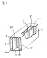
- FIG. 3 shows a perspective view of the telescopic boom, with a piece of the outer wall broken open to the interior clarify.
- the additional webs 27 and 29 not from a continuous wall, but from individual wall elements.
- another telescopic section einschiebbar the same construction, as in this embodiment shown, may have.
- FIG. 4 shows an exemplary embodiment of a cross section of a device according to the invention Telescopic boom.
- each telescopic section has four chain hoists 501 to 504 and 505 to 508. These chain hoists are in the cavities 201, 202, 203 and 204, as well as 301, 302, 303 and 304, through the vertical webs 27, 29, 37 and 39, and the additional Horizontal webs 23, 25, 33 and 35 are incurred led. Chain hoists 501 to 508 are due to the location within the cavities 201 to 204 and 301 to 304 in addition Protected from the weather.
- the webs 501, 502, 503 and 504 are adapted to the static load pattern of the telescopic shots, resulting in - looking at the cross section - from the center to the outside increasing wall thicknesses. In the present case, therefore, the wall thickness S 1 is smaller S 2 .
- the invention is based, as apparent to those skilled in, even in others Cross-sections feasible, for example, circular, elliptical, triangular and hexagonal.
- the stabilizing webs are each to be arranged in such a way that at least the Whip effect is counteracted.
Abstract
Description
Die vorliegende Erfindung betrifft einen Teleskopausleger für Hubarbeitsbühnen nach dem Oberbegriff des Patentanspruchs 1.The present invention relates to a telescopic boom for aerial work platforms according to the preamble of claim 1.
Hubarbeitsbühnen im Sinne der Erfindung umfassen einen meist fahrbaren oder selbstfahrbaren Unterbau, auf dem ein Teleskopausleger befestigt ist, dem Teleskopausleger selbst und einem, an dem Teleskopausleger befestigten Arbeitskorb. Dabei ist der Teleskopausleger so konstruiert, dass mit ihm der Arbeitskorb sowohl in eine große Höhe, als auch in eine seitlich zum fahrbaren Unterbau versetzte Lage beförderbar ist. Je größer die Höhe und je weiter die seitliche Reichweite, desto größere Anforderungen werden an das Material und die Konstruktion des Teleskopauslegers gestellt. Der Teleskopausleger selbst besteht meist aus mehreren Teleskopschüssen, die mittels Ketten, Seilzügen oder einem hydraulischen Verfahren soweit ausfahren werden können, dass die nötige Arbeitshöhe erreicht wird. Als Material zum Fertigen der Teleskopausleger wird zumeist Stahl verwendet. Es gibt jedoch auch Teleskopausleger aus Aluminium.Lifting work platforms in the context of the invention comprise a mostly mobile or self-propelled base on which a telescopic boom is attached, the telescopic boom itself and a work basket attached to the telescopic boom. The telescopic boom is designed so that with him the work basket both in a high altitude, as well as in a laterally offset to the movable base location is transportable. The larger the height and the farther the lateral reach, the larger Demands are made on the material and construction of the telescopic boom posed. The telescopic boom itself usually consists of several telescopic shots, by means of chains, cables or a hydraulic process so far can be extended that the necessary working height is achieved. As a material Steel is usually used to manufacture the telescopic boom. There are, however also telescopic boom made of aluminum.
Aus dem Stand der Technik ist eine Reihe an Konstruktionsprinzipien für Teleskopausleger bekannt. So beschreiben beispielsweise die europäische Patentanmeldung EP 0 668 238 und das Gebrauchsmuster DE 298 13 374 U zwei verschiedene, besonders den Belastungsanforderungen des Teleskopauslegers angepasste Teleskopauslegerprofile von Teleskopschüssen. Dabei muss berücksichtigt werden, dass auf der einen Seite eines Teleskopschusses ein erhöhter Zug wirkt, während auf der anderen Seite des Teleskopschusses erhöhte Druckkräfte wirken. Beide in diesen Schriften beschriebenen Teleskopauslegerprofile sind so konstruiert, dass die starken Zug- bzw. Druckkräfte aufgrund des Teleskopauslegerprofils reduziert werden.From the prior art is a number of design principles for telescopic boom known. For example, describe the European patent application EP 0 668 238 and the utility model DE 298 13 374 U two different, especially adapted to the load requirements of the telescopic boom telescopic boom profiles of telescopic shots. It must be remembered that on the one side of a telescopic section, an increased pull acts while on the On the other side of the telescopic section increased pressure forces act. Both in these Fonts described telescopic boom profiles are designed so that the strong Tensile or compressive forces due to the telescopic boom profile can be reduced.
Nachteilig an den bekannten Konstruktionsprinzipien ist jedoch, dass zwar die Druck- und Zugkräfte minimalisiert werden können, dem Teleskopausleger jedoch aufgrund der Schwere des meist verwendeten Materials - Stahl - Höhengrenzen und Grenzen in der seitlichen Reichweite gesetzt sind. Im Fall von Aluminium ist zwar das Gewicht reduziert, allerdings weist dieses Metall auch eine höhere Elastizität auf. Bei großen Höhen kann es deshalb zu einem Nachschwingen des Teleskopauslegers bei Belastungsänderung - dem sogenannten Peitscheneffekt- kommen.A disadvantage of the known construction principles, however, is that although the pressure and tensile forces can be minimized, but the telescopic boom due the severity of the most used material - steel - height limits and boundaries are set in the lateral reach. In the case of aluminum, the weight is indeed reduced, but this metal also has a higher elasticity. For big ones Heights may therefore cause the telescopic boom to vibrate when the load changes - the so-called whip effect come.
Aus der DE 27 03 539 A1 ist ein Teleskopausleger mit teleskopisch ineinander schiebbaren achteckigen Querschnittsprofilen bekannt, der dem Oberbegriff des unabhängigen Anspruchs 1 entspricht. Ein Auslegerquerschnitt besteht aus einer Kopfplatte und einer Bodenplatte und einem Paar von Seitenflächen, wobei jede Seitenfläche einen mittleren Teil aufweist, der senkrecht zu den genannten Kopf- und Bodenplatten verläuft und oberhalb und unterhalb geneigte Teile aufweist, welche den mittleren Teil mit der genannten Kopfplatte und der Bodenplatte verbinden. Diese Druckschrift zeigt außerdem, dass eine Verstärkung durch vertikale Verstärkerplatten erfolgen kann, die sich zwischen den Kopfplatten und den Bodenplatten erstrecken und parallel zueinander angeordnet sind. Als Material für den Ausleger ist Stahl angegeben.From DE 27 03 539 A1 a telescopic boom with telescopic one another sliding octagonal cross-sectional profiles known, which corresponds to the preamble of independent claim 1. A boom cross-section exists a top plate and a bottom plate and a pair of side surfaces, each side surface having a central portion perpendicular to said Top and bottom plates and has above and below inclined parts, which the middle part with said head plate and the bottom plate connect. This document also shows that amplification by vertical Amplifier plates can be made that extend between the top plates and the bottom plates extend and are arranged parallel to each other. As material for the boom Steel is specified.
Aufgabe vorliegender Erfindung ist es, einen Teleskopausleger bereitzustellen, der so konstruiert ist, dass er aus Materialien mit geringem spezifischen Gewicht fertigbar ist, aber keinen Peitscheneffekt aufweist.Object of the present invention is to provide a telescopic boom, the designed so that it can be manufactured from materials with low specific weight is, but has no whip effect.
Diese Aufgabe wird erfindungsgemäß durch einen Teleskopausleger mit den Merkmalen des Patentanspruchs 1 gelöst.This object is achieved by a telescopic boom with the features of claim 1.
Vorteilhafte Ausgestaltungen des erfindungsgemäßen Teleskopauslegers sind in den jeweiligen Unteransprüchen beschrieben.Advantageous embodiments of the telescopic boom according to the invention are in the respective subclaims described.
Erfindungsgemäß weist der Teleskopschuss innerhalb des ersten Hohlraumes zwei Stege auf, die parallel zueinander angeordnet sind und mit denen zwei weitere Hohlräume bildbar sind. Innerhalb der neu entstandenen Hohlräume sind weitere Stege angeordnet.According to the invention, the telescopic section within the first cavity has two Webs which are arranged parallel to each other and with which two further cavities are imageable. Within the newly created cavities are more bridges arranged.
Die in dem Hohlraum des Teleskopschusses zur Stabilisierung angeordneten Stege verringern die Elastizität des Teleskopauslegers. Der bei großen Höhen auftretende Peitscheneffekt wird deshalb wirksam reduziert.The webs arranged in the cavity of the telescopic section for stabilization reduce the elasticity of the telescopic boom. The occurring at high altitudes Whip effect is therefore effectively reduced.
Sind die weiteren Stege nicht parallel zu den schon existierenden hohlraumbildenden Stegen angeordnet, sondern senkrecht dazu, können vorteilhafterweise auch Querkräfte aufgefangen werden, die auf den Teleskopausleger wirken.Are the other webs not parallel to the already existing cavity forming Webs arranged, but perpendicular thereto, can advantageously also lateral forces be caught, which act on the telescopic boom.
Durch die symmetrische Anordnung wird zusätzlich einerseits die Kraft verteilt, andererseits der erste Hohlraum nicht so eingeschränkt, dass kein zweiter oder dritter Teleskopschuss in den ersten Teleskopschuss einschiebbar ist.Due to the symmetrical arrangement, on the one hand, the force is distributed, on the other hand the first cavity is not so limited that no second or third telescopic shot in the first telescopic shot can be inserted.
Die Stege müssen, wie in einem bevorzugten Ausführungsbeispiel, nicht als durchgängige Längswand gefertigt sein, sondern können auch aus vielen Einzelstegen bestehen. Durch die Ausführung mit derart durchbrochenen Wänden ist eine weitere Gewichtseinsparung möglich.The webs must, as in a preferred embodiment, not as continuous Can be made longitudinal wall, but can also be made of many single webs consist. The execution with such broken walls is another Weight saving possible.
Besonders vorteilhaft ist ein Ausführungsbeispiel, bei dem die Außenwand des Teleskopschusses zwei Horizontalstege und zwei Vertikalstege umfasst, die ein kastenförmiges Teleskopauslegerprofil bilden. Diese Teleskopauslegerprofilform hat sich als besonders vorteilhaft erwiesen. Dabei können unter anderem auch ein oder mehrere Vertikalstege abgewinkelt sein, um ein Teleskopauslegerprofil bereitzustellen, das optimal für die auf es wirkenden Druckkräfte konstruiert ist.Particularly advantageous is an embodiment in which the outer wall of the telescopic section comprises two horizontal webs and two vertical webs, which is a box-shaped Form telescopic boom profile. This telescopic boom profile shape has become proved to be particularly advantageous. Among other things, one or more Vertical webs to provide a telescoping boom profile, which is optimally designed for the compressive forces acting on it.
In einem weiteren Ausführungsbeispiel sind die in dem Hohlraum angeordneten Stege so ausgebildet, dass sie parallel zu den abgewinkelten Vertikalstegen des Teleskopauslegerprofils ausgebildet sind. Sie treffen dort auf den Horizontalsteg, an dem die abgewinkelten Vertikalstege auf den Horizontalsteg treffen.In a further embodiment, the webs arranged in the cavity are designed so that they are parallel to the angled vertical webs of the telescopic boom profile are formed. They meet there on the horizontal bar, on which meet the angled vertical webs on the horizontal web.
Vorteilhafterweise können in den Hohlräumen bandförmige Objekte, insbesondere Stromleitungen, Ketten und Seilzüge in besonders geschützter Form geführt werden. Advantageously, in the cavities band-shaped objects, in particular Power lines, chains and cables are guided in a particularly protected form.
Dies stellt nicht nur einen besonderen Schutz gegen Witterungseinflüsse für Ketten und Seilzüge dar, sondern auch gegenüber dem eingeschobenen nächsten Teleskopschuss. Darüber hinaus wird die Lärmbelästigung von schwingenden Ketten oder Seilen beim Aus- oder Einfahren des Teleskopauslegers für die Bedienperson auf ein Minimum reduziert.This not only provides a special protection against the weather for chains and cables, but also against the inserted next telescopic shot. In addition, the noise pollution from vibrating chains or ropes when extending or retracting the telescopic boom for the operator reduced to a minimum.
Besonders vorteilhaft ist ein Ausführungsbeispiel des erfindungsgemäßen Teleskopauslegers, bei dem mindestens ein Teleskopschuss aus Faserverbundwerkstoffen, insbesondere Kevlargewebe und/oder Carbonfaser und/oder Gießharz, gefertigt ist. Aufgrund der besonderen Konstruktion des Teleskopschusses ist die Verwendung solcher Materialien möglich. Bei diesen Materialien bestand das Problem, dass sie eine so hohe Elastizität aufweisen, dass der Peitscheneffekt potenziert wurde. Aufgrund der elastizitätsreduzierenden Konstruktion des erfindungsgemäßen Teleskopauslegers ist jedoch der Einsatz solcher Materialien möglich. Dies erlaubt eine größere Arbeitshöhe und Reichweite, da der Ausleger insgesamt leichter ausgebildet ist.Particularly advantageous is an embodiment of the telescopic boom according to the invention, in which at least one telescopic section of fiber composite materials, in particular Kevlar fabric and / or carbon fiber and / or casting resin is made. Due to the special construction of the telescopic section is the use such materials possible. These materials had the problem that they have such high elasticity that the whip effect has been potentiated. by virtue of the elasticity-reducing construction of the telescopic boom according to the invention However, the use of such materials is possible. This allows a larger one Working height and reach, as the boom is designed to be lighter overall.
Weitere Einzelheiten, Vorteile und Merkmale ergeben sich aus den folgenden, in den Figuren dargestellten Ausführungsbeispielen.Further details, advantages and features emerge from the following, in the Figures illustrated embodiments.
Es zeigen:
- Figur 1:
- eine schematische Darstellung eines ersten Beispiels eines Querschnitts eines Teleskopauslegers;
- Figur 2:
- eine schematische Darstellung eines zweiten Beispiels eines Querschnitts eines Teleskopauslegers;
- Figur 3:
- eine perspektivische Darstellung mit teilweise durchbrochener Außenwand eines dritten Beispiels eines Teleskopauslegers;
- Figur 4:
- eine schematische Darstellung eines Ausführungsbeispiels eines Querschnitts eines erfindungsgemäßen Teleskopauslegers; und
- Figur 5:
- eine schematische Darstellung eines weiteren Beispiels eines Querschnitts eines Teleskopauslegers.
- FIG. 1:
- a schematic representation of a first example of a cross section of a telescopic boom;
- FIG. 2:
- a schematic representation of a second example of a cross section of a telescopic boom;
- FIG. 3:
- a perspective view with partially broken outer wall of a third example of a telescopic boom;
- FIG. 4:
- a schematic representation of an embodiment of a cross section of a telescopic boom according to the invention; and
- FIG. 5:
- a schematic representation of another example of a cross section of a telescopic boom.
Im Folgenden sind gleiche oder gleichartige Elemente mit gleichen Bezugszeichen bezeichnet.The following are the same or similar elements with the same reference numerals designated.
Figur 1 zeigt eine schematische Darstellung eines ersten Ausführungsbeispiels eines
Querschnitts des Teleskopauslegers 10. Dabei besteht der Teleskopausleger
10 aus einem ersten Teleskopschuss 20 und einem in einem Hohlraum
200 angeordneten zweiten Teleskopschuss 30. Der Querschnitt zeigt ein kastenförmiges
Auslegerprofil mit jeweils zwei Horizontalstegen 22, 24, 32 und 34, sowie
jeweils zwei Vertikalstegen 26, 28, 36 und 38. Beide Vertikalstege 26 und 28
weisen schräg abgekantete Enden auf, bezeichnet mit 26a und 28a. Die Vertikalstege
36 und 38 weisen ebenfalls zwei vertikal abgekantete Ecken 36a und 38a auf.
Zusätzlich ist der Hohlraum 200 mittels zweier weiterer parallel zu den Vertikalstegen
26 und 28 ausgerichteten weiteren Stegen 27 und 29 so unterteilt, dass zwei weitere
Hohlräume 202 und 204 gebildet werden. Auch der zweite Teleskopschuss 30 weist
zwei weitere Vertikalstege 37 und 39 auf, die jeweils parallel zu den Vertikalstegen
36 und 38 angeordnet sind. Sie unterteilen den Hohlraum 300 ebenfalls in zwei weitere
Hohlräume 302 und 304. In den Hohlraum 300 kann ein weitere Teleskopschuss
eingeschoben werden. Im Betrieb ist der Teleskopausleger so orientiert, daß die Vertikalstege
vertikal, die Horizontalstege horizontal ausgerichtet sind.Figure 1 shows a schematic representation of a first embodiment of a
Cross section of the
Figur 2 zeigt ein zweites Ausführungsbeispiel des Teleskopauslegers
10. Dieses weist drei Teleskopschüsse 20, 30 und 40 auf. Dabei ist der Teleskopschuss
30 in den Hohlraum 200 des Teleskopschusses 20, und der Teleskopschuss
40 in den Hohlraum 300 des Teleskopschusses 30 eingeschoben und der
Teleskopschuss 40 weist einen weiteren Hohlraum 400 auf. Der Querschnitt der Teleskopschüsse
20, 30 und 40 ist kastenförmig mit jeweils zwei Horizontalstegen 22,
24, 32, 34, 42 und 44 und jeweils zwei Vertikalstegen 26, 28, 36, 38, 46 und 48. Parallel
zu den Vertikalstegen 26, 28, 36 und 38 sind wiederum zwei zusätzliche Stege
27, 29, 37 und 39 angeordnet. Im Gegensatz zu den Teleskopschüssen 20 und 30
weist jedoch der innerste Teleskopschuss 40 keine zwei, sondern einen im Hohlraum
400 zentriert angeordneten zusätzlichen Steg 47 auf.Figure 2 shows a second embodiment of the
Figur 3 zeigt eine perspektivische Darstellung des Teleskopauslegers,
wobei ein Stück der Außenwand aufgebrochen ist, um das Innenleben zu
verdeutlichen. In diesem Ausführungsbeispiel bestehen die zusätzlichen Stege 27
und 29 nicht aus einer durchgehenden Wand, sondern aus einzelnen Wandelementen.
In den Hohlraum 200 ist, wie in Figur 1 oder in Figur 2 gezeigt, ein weiterer Teleskopschuss
einschiebbar, der eine gleiche Konstruktionsweise, wie in diesem Ausführungsbeispiel
gezeigt, aufweisen kann.FIG. 3 shows a perspective view of the telescopic boom,
with a piece of the outer wall broken open to the interior
clarify. In this embodiment, the
Figur 4 zeigt ein Ausführungsbeispiel eines Querschnitts eines erfindungsgemäßen
Teleskopauslegers. Dabei sind zusätzlich zu den in Figur 1, Figur 2 oder
Figur 3 beschriebenen Elementen in den Hohlräumen 202 und 204, sowie 302 und
304 jeweils zwei zusätzliche Horizontalstege 23, 25, 33 und 35 eingebaut. Diese reduzieren
auch Querkräfte, die auf den Teleskopausleger 10 wirken. Außerdem weist
in Figur 4 jeder Teleskopschuss vier Kettenzüge 501 bis 504 und 505 bis 508 auf.
Diese Kettenzüge sind in den Hohlräumen 201, 202, 203 und 204, sowie 301, 302,
303 und 304, die durch die Vertikalstege 27, 29, 37 und 39, sowie die zusätzlichen
Horizontalstege 23, 25, 33 und 35 entstanden sind, geführt. Die Kettenzüge 501 bis
508 sind durch die Lage innerhalb der Hohlräume 201 bis 204 sowie 301 bis 304 zusätzlich
vor Witterungseinflüssen geschützt.FIG. 4 shows an exemplary embodiment of a cross section of a device according to the invention
Telescopic boom. In addition to those in Figure 1, Figure 2 or
3 described elements in the
Bei dem in Figur 5 dargestellten Ausführungsbeispiel eines Querschnitts eines
Teleskopauslegers sind die Stege 501, 502, 503 und 504 an das statische
Belastungsbild der Teleskopschüsse angepaßt, wodurch sich - bei Betrachtung
des Querschnitts - von der Mitte nach außen zunehmende Wanddicken ergeben.
Vorliegend ist deshalb die Wandstärke S1 kleiner S2.In the embodiment of a cross section of a telescopic boom shown in Figure 5, the
Neben den dargestellten Ausführungsformen für Teleskopausleger ist die Idee, die der Erfindung zugrundeliegt, wie für den Fachmann offensichtlich, auch bei anderen Querschnitten realisierbar, beispielsweise kreisrund, elliptisch, dreieckig und sechseckig. Die Stabilisierungsstege sind jeweils so darin anzuordnen, daß zumindest dem Peitscheneffekt entgegengewirkt wird.In addition to the illustrated embodiments for telescopic boom is the idea that the invention is based, as apparent to those skilled in, even in others Cross-sections feasible, for example, circular, elliptical, triangular and hexagonal. The stabilizing webs are each to be arranged in such a way that at least the Whip effect is counteracted.
Claims (10)
- A telescopic jib (10) for lifting working platforms comprising at least a first and a second telescopic section (20; 30) which in cross-section are each of a telescopic jib profile with a first cavity (200; 300) disposed therein, wherein the first telescopic section (20) is of such a configuration that its inside dimension is larger than the outside dimension or the second telescopic section (30) and the second telescopic section (30) can be pushed into the first telescopic section (20), and wherein at least one telescopic section (20; 30) within the first, cavity (200; 300) has two limbs (27, 29; 37; 39) which are arranged parallel to each other and with which two further cavities (202, 204; 302, 304) can be formed,
characterised in that
at least one telescopic section (20; 30) within the at least two further cavities (202, 204; 301, 304) has at least one further limb (23; 25; 33; 35). - A telescopic jib (10) according to claim 1 characterised in that the at least one limb (27; 29; 37; 39) is in the form of a continuous or non-continuous wall along the longitudinal axis of the telescopic section (20; 30).
- A telescopic jib (10) according to claim 1 or claim 2 characterised in that at least one telescopic section (20; 30) includes two horizontal limbs (22; 24; 32; 34) and two vertical limbs (26; 28; 36; 38) which co-operate in such a way that a box-shaped telescopic jib profile can be formed.
- A telescopic jib (10) according to claim 3 characterised in that at least one vertical limb (26a; 28a; 36a; 38a) is angled.
- A telescopic jib (10) according to claim 4 characterised in that the at least one further limb (27; 29; 37; 39) arranged in the first cavity (200) is so arranged that in parallel relationship with the at least one angled vertical limb (26a: 28a; 36a; 38a) it forms a third vertical limb (27, 29) which is also operatively connected to the horizontal limb (24; 34) at the location at which the angled end of the at least one angled vertical limb (26a; 28a; 36a; 38a) co-operates with the horizontal limb (24; 34).
- A telescopic jib (10) according to one of the preceding claims characterised in that the telescopic sections (20; 30) are connected together by way of one or more band-form objects, in particular by way of power lines, chain and cable tackles (501-508), wherein the band-form objects are arranged in the at least one further cavity (202; 204; 302; 304).
- A telescopic jib (10) according to one of the preceding claims characterised in that the box-shaped telescopic jib profile has at least one rounded corner.
- A telescopic jib (10) according to one of the preceding claims characterised in that the at least one telescopic section (20; 30) is made from fibre composite material, in particular Kcvlar weave and/or carbon fibres and/or casting resin.
- A telescopic jib (10) according to one of the preceding claims characterised in that at least one limb (501; 502, 503; 504) of a telescopic section is adapted in its wall thickness dimensioning to the static loading profile of the telescopic section, wherein when considering the cross-section of the telescopic section in particular the wall thickness of the at least one limb increases from the interior of the telescopic section outwardly.
- A mobile lifting working platform having a telescopic jib (10) according to one of the preceding claims.
Priority Applications (3)
| Application Number | Priority Date | Filing Date | Title |
|---|---|---|---|
| EP01122288A EP1293470B1 (en) | 2001-09-18 | 2001-09-18 | Telescopic jib for work platforms |
| DE50108249T DE50108249D1 (en) | 2001-09-18 | 2001-09-18 | Telescopic boom for aerial work platforms |
| AT01122288T ATE311340T1 (en) | 2001-09-18 | 2001-09-18 | TELESCOPIC BOOM FOR ELEVATOR WORK PLATFORMS |
Applications Claiming Priority (1)
| Application Number | Priority Date | Filing Date | Title |
|---|---|---|---|
| EP01122288A EP1293470B1 (en) | 2001-09-18 | 2001-09-18 | Telescopic jib for work platforms |
Publications (2)
| Publication Number | Publication Date |
|---|---|
| EP1293470A1 EP1293470A1 (en) | 2003-03-19 |
| EP1293470B1 true EP1293470B1 (en) | 2005-11-30 |
Family
ID=8178655
Family Applications (1)
| Application Number | Title | Priority Date | Filing Date |
|---|---|---|---|
| EP01122288A Expired - Lifetime EP1293470B1 (en) | 2001-09-18 | 2001-09-18 | Telescopic jib for work platforms |
Country Status (3)
| Country | Link |
|---|---|
| EP (1) | EP1293470B1 (en) |
| AT (1) | ATE311340T1 (en) |
| DE (1) | DE50108249D1 (en) |
Cited By (1)
| Publication number | Priority date | Publication date | Assignee | Title |
|---|---|---|---|---|
| KR101390093B1 (en) * | 2012-05-03 | 2014-04-29 | 주식회사 호룡 | Boom for aerial work platform |
Family Cites Families (7)
| Publication number | Priority date | Publication date | Assignee | Title |
|---|---|---|---|---|
| GB1564509A (en) * | 1976-01-29 | 1980-04-10 | Coles Cranes Ltd | Octagonal crane boom |
| DE4328459A1 (en) * | 1993-08-24 | 1995-05-11 | Euraplan Ingenieurgesellschaft | Lifting platform |
| JPH0812255A (en) * | 1994-06-28 | 1996-01-16 | Aichi Corp | Boom structure |
| DE19631547B4 (en) * | 1996-07-24 | 2004-05-06 | Terex-Demag Gmbh & Co. Kg | Telescopic boom, especially for stationary or mobile cranes |
| DE19824672A1 (en) * | 1997-05-28 | 1998-12-03 | Mannesmann Ag | Telescopic boom crane |
| DE19829829A1 (en) * | 1998-07-03 | 2000-01-13 | Grove Us Llc Shady Grove | Composite telescopic part and boom |
| DE10030190A1 (en) * | 1999-06-22 | 2001-05-31 | Atecs Mannesmann Ag | Telescopic boom for vehicle cranes has telescopic arms with profiled shell made from profiled sheet metal with varying nominal wall thickness adapted to load but with constant internal hollow dimensions |
-
2001
- 2001-09-18 AT AT01122288T patent/ATE311340T1/en not_active IP Right Cessation
- 2001-09-18 DE DE50108249T patent/DE50108249D1/en not_active Expired - Fee Related
- 2001-09-18 EP EP01122288A patent/EP1293470B1/en not_active Expired - Lifetime
Cited By (1)
| Publication number | Priority date | Publication date | Assignee | Title |
|---|---|---|---|---|
| KR101390093B1 (en) * | 2012-05-03 | 2014-04-29 | 주식회사 호룡 | Boom for aerial work platform |
Also Published As
| Publication number | Publication date |
|---|---|
| EP1293470A1 (en) | 2003-03-19 |
| DE50108249D1 (en) | 2006-01-05 |
| ATE311340T1 (en) | 2005-12-15 |
Similar Documents
| Publication | Publication Date | Title |
|---|---|---|
| EP2504267B1 (en) | Mobile telescopic crane | |
| EP0516938B1 (en) | Device for the stepwise raising of heavy weights for tower cranes or working platforms | |
| DE102011016015B4 (en) | Lattice boom crane and lattice boom | |
| DE102009016033A1 (en) | Lattice boom crane and lattice boom | |
| LU86532A1 (en) | TELESCOPIC COLUMN | |
| DE10128986A1 (en) | Mobile crane has load increasing device permanently connected to main jib part and with individual weight of telescopic extensions each reduced to avoid exceeding maximum permissible weight without having to reduce number of extensions | |
| EP3274288B1 (en) | Crane tower | |
| DE19732451C2 (en) | Rope arrangement for hanging a lifting gear on a hoist, especially for overhead cranes or trolleys | |
| EP1293470B1 (en) | Telescopic jib for work platforms | |
| EP2427609B1 (en) | Scaffolding system, method for erecting a scaffolding system and method for using such a scaffolding system | |
| EP1205421A1 (en) | Method and device for transporting lattice tower cranes | |
| DE2229318A1 (en) | TOWER CRANE | |
| DE2703539C2 (en) | ||
| DE202016100483U1 (en) | Vehicle light crane with telescopic folding tip | |
| DE4425777C2 (en) | Hoist, especially for overhead cranes, trolleys and. the like | |
| DE2721636A1 (en) | SETUP ON CHARGERS WITH TELESCOPIC EXTENSIBLE BOOM AND WITH HYDRAULIC LINES CARRIED BY THE BOOM | |
| DE102012210112B3 (en) | Mobile telescopic crane comprises telescopic arm with three sub-arms, where lower sub-arm faces undercarriage and two upper sub-arms are turned away from undercarriage and are hinged to undercarriage, and sub-arm is made of sub-arm sections | |
| DE3316365A1 (en) | QUICK ASSEMBLY BOOM FOR A VEHICLE CRANE | |
| DE3231074C2 (en) | Boom for cranes | |
| EP1136428B1 (en) | Lifting device for a lift-truck | |
| DE102012210109B3 (en) | Mobile telescopic crane has rigid connection elements that are provided with cantilever portions respectively, and upper sub-arms that are faced away from wheeled undercarriage and are partially formed using fiber composite material | |
| DE8508047U1 (en) | Lifting device | |
| DE3911044C2 (en) | ||
| DE102020128161A1 (en) | tower crane | |
| DE102008032976B4 (en) | A telescopic crane jib part |
Legal Events
| Date | Code | Title | Description |
|---|---|---|---|
| PUAI | Public reference made under article 153(3) epc to a published international application that has entered the european phase |
Free format text: ORIGINAL CODE: 0009012 |
|
| AK | Designated contracting states |
Kind code of ref document: A1 Designated state(s): AT BE CH CY DE DK ES FI FR GB GR IE IT LI LU MC NL PT SE TR |
|
| AX | Request for extension of the european patent |
Extension state: AL LT LV MK RO SI |
|
| 17P | Request for examination filed |
Effective date: 20030917 |
|
| AKX | Designation fees paid |
Designated state(s): AT BE CH CY DE DK ES FI FR GB GR IE IT LI LU MC NL PT SE TR |
|
| 17Q | First examination report despatched |
Effective date: 20040716 |
|
| GRAP | Despatch of communication of intention to grant a patent |
Free format text: ORIGINAL CODE: EPIDOSNIGR1 |
|
| GRAS | Grant fee paid |
Free format text: ORIGINAL CODE: EPIDOSNIGR3 |
|
| RAP1 | Party data changed (applicant data changed or rights of an application transferred) |
Owner name: PALFINGER EUROPE GMBH |
|
| RIN1 | Information on inventor provided before grant (corrected) |
Inventor name: FRANZ-PETER JENNISSEN |
|
| GRAA | (expected) grant |
Free format text: ORIGINAL CODE: 0009210 |
|
| AK | Designated contracting states |
Kind code of ref document: B1 Designated state(s): AT BE CH CY DE DK ES FI FR GB GR IE IT LI LU MC NL PT SE TR |
|
| PG25 | Lapsed in a contracting state [announced via postgrant information from national office to epo] |
Ref country code: GB Free format text: LAPSE BECAUSE OF FAILURE TO SUBMIT A TRANSLATION OF THE DESCRIPTION OR TO PAY THE FEE WITHIN THE PRESCRIBED TIME-LIMIT Effective date: 20051130 Ref country code: FI Free format text: LAPSE BECAUSE OF FAILURE TO SUBMIT A TRANSLATION OF THE DESCRIPTION OR TO PAY THE FEE WITHIN THE PRESCRIBED TIME-LIMIT Effective date: 20051130 Ref country code: IE Free format text: LAPSE BECAUSE OF FAILURE TO SUBMIT A TRANSLATION OF THE DESCRIPTION OR TO PAY THE FEE WITHIN THE PRESCRIBED TIME-LIMIT Effective date: 20051130 Ref country code: NL Free format text: LAPSE BECAUSE OF FAILURE TO SUBMIT A TRANSLATION OF THE DESCRIPTION OR TO PAY THE FEE WITHIN THE PRESCRIBED TIME-LIMIT Effective date: 20051130 Ref country code: IT Free format text: LAPSE BECAUSE OF FAILURE TO SUBMIT A TRANSLATION OF THE DESCRIPTION OR TO PAY THE FEE WITHIN THE PRESCRIBED TIME-LIMIT;WARNING: LAPSES OF ITALIAN PATENTS WITH EFFECTIVE DATE BEFORE 2007 MAY HAVE OCCURRED AT ANY TIME BEFORE 2007. THE CORRECT EFFECTIVE DATE MAY BE DIFFERENT FROM THE ONE RECORDED. Effective date: 20051130 |
|
| REG | Reference to a national code |
Ref country code: CH Ref legal event code: EP Ref country code: GB Ref legal event code: FG4D Free format text: NOT ENGLISH |
|
| REG | Reference to a national code |
Ref country code: IE Ref legal event code: FG4D Free format text: LANGUAGE OF EP DOCUMENT: GERMAN |
|
| REF | Corresponds to: |
Ref document number: 50108249 Country of ref document: DE Date of ref document: 20060105 Kind code of ref document: P |
|
| PG25 | Lapsed in a contracting state [announced via postgrant information from national office to epo] |
Ref country code: GR Free format text: LAPSE BECAUSE OF FAILURE TO SUBMIT A TRANSLATION OF THE DESCRIPTION OR TO PAY THE FEE WITHIN THE PRESCRIBED TIME-LIMIT Effective date: 20060228 Ref country code: SE Free format text: LAPSE BECAUSE OF FAILURE TO SUBMIT A TRANSLATION OF THE DESCRIPTION OR TO PAY THE FEE WITHIN THE PRESCRIBED TIME-LIMIT Effective date: 20060228 Ref country code: DK Free format text: LAPSE BECAUSE OF FAILURE TO SUBMIT A TRANSLATION OF THE DESCRIPTION OR TO PAY THE FEE WITHIN THE PRESCRIBED TIME-LIMIT Effective date: 20060228 |
|
| PG25 | Lapsed in a contracting state [announced via postgrant information from national office to epo] |
Ref country code: ES Free format text: LAPSE BECAUSE OF FAILURE TO SUBMIT A TRANSLATION OF THE DESCRIPTION OR TO PAY THE FEE WITHIN THE PRESCRIBED TIME-LIMIT Effective date: 20060313 |
|
| PG25 | Lapsed in a contracting state [announced via postgrant information from national office to epo] |
Ref country code: PT Free format text: LAPSE BECAUSE OF FAILURE TO SUBMIT A TRANSLATION OF THE DESCRIPTION OR TO PAY THE FEE WITHIN THE PRESCRIBED TIME-LIMIT Effective date: 20060502 |
|
| NLV1 | Nl: lapsed or annulled due to failure to fulfill the requirements of art. 29p and 29m of the patents act | ||
| GBV | Gb: ep patent (uk) treated as always having been void in accordance with gb section 77(7)/1977 [no translation filed] |
Effective date: 20051130 |
|
| REG | Reference to a national code |
Ref country code: IE Ref legal event code: FD4D |
|
| PG25 | Lapsed in a contracting state [announced via postgrant information from national office to epo] |
Ref country code: MC Free format text: LAPSE BECAUSE OF NON-PAYMENT OF DUE FEES Effective date: 20060930 Ref country code: LI Free format text: LAPSE BECAUSE OF NON-PAYMENT OF DUE FEES Effective date: 20060930 Ref country code: CH Free format text: LAPSE BECAUSE OF NON-PAYMENT OF DUE FEES Effective date: 20060930 Ref country code: BE Free format text: LAPSE BECAUSE OF NON-PAYMENT OF DUE FEES Effective date: 20060930 |
|
| PLBE | No opposition filed within time limit |
Free format text: ORIGINAL CODE: 0009261 |
|
| STAA | Information on the status of an ep patent application or granted ep patent |
Free format text: STATUS: NO OPPOSITION FILED WITHIN TIME LIMIT |
|
| 26N | No opposition filed |
Effective date: 20060831 |
|
| EN | Fr: translation not filed | ||
| PG25 | Lapsed in a contracting state [announced via postgrant information from national office to epo] |
Ref country code: DE Free format text: LAPSE BECAUSE OF NON-PAYMENT OF DUE FEES Effective date: 20070403 |
|
| REG | Reference to a national code |
Ref country code: CH Ref legal event code: PL |
|
| PG25 | Lapsed in a contracting state [announced via postgrant information from national office to epo] |
Ref country code: AT Free format text: LAPSE BECAUSE OF NON-PAYMENT OF DUE FEES Effective date: 20060918 |
|
| BERE | Be: lapsed |
Owner name: PALFINGER EUROPE GMBH Effective date: 20060930 |
|
| PG25 | Lapsed in a contracting state [announced via postgrant information from national office to epo] |
Ref country code: FR Free format text: LAPSE BECAUSE OF FAILURE TO SUBMIT A TRANSLATION OF THE DESCRIPTION OR TO PAY THE FEE WITHIN THE PRESCRIBED TIME-LIMIT Effective date: 20070119 |
|
| PG25 | Lapsed in a contracting state [announced via postgrant information from national office to epo] |
Ref country code: LU Free format text: LAPSE BECAUSE OF NON-PAYMENT OF DUE FEES Effective date: 20060918 Ref country code: TR Free format text: LAPSE BECAUSE OF FAILURE TO SUBMIT A TRANSLATION OF THE DESCRIPTION OR TO PAY THE FEE WITHIN THE PRESCRIBED TIME-LIMIT Effective date: 20051130 |
|
| PG25 | Lapsed in a contracting state [announced via postgrant information from national office to epo] |
Ref country code: FR Free format text: LAPSE BECAUSE OF FAILURE TO SUBMIT A TRANSLATION OF THE DESCRIPTION OR TO PAY THE FEE WITHIN THE PRESCRIBED TIME-LIMIT Effective date: 20051130 Ref country code: CY Free format text: LAPSE BECAUSE OF FAILURE TO SUBMIT A TRANSLATION OF THE DESCRIPTION OR TO PAY THE FEE WITHIN THE PRESCRIBED TIME-LIMIT Effective date: 20051130 |