EP2504267B1 - Mobile telescopic crane - Google Patents
Mobile telescopic crane Download PDFInfo
- Publication number
- EP2504267B1 EP2504267B1 EP11797251.3A EP11797251A EP2504267B1 EP 2504267 B1 EP2504267 B1 EP 2504267B1 EP 11797251 A EP11797251 A EP 11797251A EP 2504267 B1 EP2504267 B1 EP 2504267B1
- Authority
- EP
- European Patent Office
- Prior art keywords
- boom
- jib
- telescopic crane
- crane according
- mobile telescopic
- Prior art date
- Legal status (The legal status is an assumption and is not a legal conclusion. Google has not performed a legal analysis and makes no representation as to the accuracy of the status listed.)
- Active
Links
- 238000005452 bending Methods 0.000 description 44
- 239000000463 material Substances 0.000 description 8
- 230000005484 gravity Effects 0.000 description 4
- 238000010276 construction Methods 0.000 description 3
- 238000005457 optimization Methods 0.000 description 3
- 239000002131 composite material Substances 0.000 description 2
- 230000007423 decrease Effects 0.000 description 2
- 238000009434 installation Methods 0.000 description 2
- 230000002093 peripheral effect Effects 0.000 description 2
- 238000010521 absorption reaction Methods 0.000 description 1
- 238000004519 manufacturing process Methods 0.000 description 1
- 238000004513 sizing Methods 0.000 description 1
- 239000004575 stone Substances 0.000 description 1
- 230000004584 weight gain Effects 0.000 description 1
- 235000019786 weight gain Nutrition 0.000 description 1
Images


Classifications
-
- B—PERFORMING OPERATIONS; TRANSPORTING
- B66—HOISTING; LIFTING; HAULING
- B66C—CRANES; LOAD-ENGAGING ELEMENTS OR DEVICES FOR CRANES, CAPSTANS, WINCHES, OR TACKLES
- B66C23/00—Cranes comprising essentially a beam, boom, or triangular structure acting as a cantilever and mounted for translatory of swinging movements in vertical or horizontal planes or a combination of such movements, e.g. jib-cranes, derricks, tower cranes
- B66C23/18—Cranes comprising essentially a beam, boom, or triangular structure acting as a cantilever and mounted for translatory of swinging movements in vertical or horizontal planes or a combination of such movements, e.g. jib-cranes, derricks, tower cranes specially adapted for use in particular purposes
- B66C23/36—Cranes comprising essentially a beam, boom, or triangular structure acting as a cantilever and mounted for translatory of swinging movements in vertical or horizontal planes or a combination of such movements, e.g. jib-cranes, derricks, tower cranes specially adapted for use in particular purposes mounted on road or rail vehicles; Manually-movable jib-cranes for use in workshops; Floating cranes
-
- B—PERFORMING OPERATIONS; TRANSPORTING
- B66—HOISTING; LIFTING; HAULING
- B66C—CRANES; LOAD-ENGAGING ELEMENTS OR DEVICES FOR CRANES, CAPSTANS, WINCHES, OR TACKLES
- B66C23/00—Cranes comprising essentially a beam, boom, or triangular structure acting as a cantilever and mounted for translatory of swinging movements in vertical or horizontal planes or a combination of such movements, e.g. jib-cranes, derricks, tower cranes
- B66C23/62—Constructional features or details
- B66C23/64—Jibs
- B66C23/70—Jibs constructed of sections adapted to be assembled to form jibs or various lengths
- B66C23/701—Jibs constructed of sections adapted to be assembled to form jibs or various lengths telescopic
-
- B—PERFORMING OPERATIONS; TRANSPORTING
- B66—HOISTING; LIFTING; HAULING
- B66C—CRANES; LOAD-ENGAGING ELEMENTS OR DEVICES FOR CRANES, CAPSTANS, WINCHES, OR TACKLES
- B66C23/00—Cranes comprising essentially a beam, boom, or triangular structure acting as a cantilever and mounted for translatory of swinging movements in vertical or horizontal planes or a combination of such movements, e.g. jib-cranes, derricks, tower cranes
- B66C23/18—Cranes comprising essentially a beam, boom, or triangular structure acting as a cantilever and mounted for translatory of swinging movements in vertical or horizontal planes or a combination of such movements, e.g. jib-cranes, derricks, tower cranes specially adapted for use in particular purposes
- B66C23/36—Cranes comprising essentially a beam, boom, or triangular structure acting as a cantilever and mounted for translatory of swinging movements in vertical or horizontal planes or a combination of such movements, e.g. jib-cranes, derricks, tower cranes specially adapted for use in particular purposes mounted on road or rail vehicles; Manually-movable jib-cranes for use in workshops; Floating cranes
- B66C23/42—Cranes comprising essentially a beam, boom, or triangular structure acting as a cantilever and mounted for translatory of swinging movements in vertical or horizontal planes or a combination of such movements, e.g. jib-cranes, derricks, tower cranes specially adapted for use in particular purposes mounted on road or rail vehicles; Manually-movable jib-cranes for use in workshops; Floating cranes with jibs of adjustable configuration, e.g. foldable
-
- B—PERFORMING OPERATIONS; TRANSPORTING
- B66—HOISTING; LIFTING; HAULING
- B66C—CRANES; LOAD-ENGAGING ELEMENTS OR DEVICES FOR CRANES, CAPSTANS, WINCHES, OR TACKLES
- B66C23/00—Cranes comprising essentially a beam, boom, or triangular structure acting as a cantilever and mounted for translatory of swinging movements in vertical or horizontal planes or a combination of such movements, e.g. jib-cranes, derricks, tower cranes
- B66C23/62—Constructional features or details
- B66C23/64—Jibs
- B66C23/70—Jibs constructed of sections adapted to be assembled to form jibs or various lengths
- B66C23/701—Jibs constructed of sections adapted to be assembled to form jibs or various lengths telescopic
- B66C23/705—Jibs constructed of sections adapted to be assembled to form jibs or various lengths telescopic telescoped by hydraulic jacks
-
- B—PERFORMING OPERATIONS; TRANSPORTING
- B66—HOISTING; LIFTING; HAULING
- B66C—CRANES; LOAD-ENGAGING ELEMENTS OR DEVICES FOR CRANES, CAPSTANS, WINCHES, OR TACKLES
- B66C23/00—Cranes comprising essentially a beam, boom, or triangular structure acting as a cantilever and mounted for translatory of swinging movements in vertical or horizontal planes or a combination of such movements, e.g. jib-cranes, derricks, tower cranes
- B66C23/62—Constructional features or details
- B66C23/64—Jibs
- B66C23/70—Jibs constructed of sections adapted to be assembled to form jibs or various lengths
- B66C23/701—Jibs constructed of sections adapted to be assembled to form jibs or various lengths telescopic
- B66C23/707—Jibs constructed of sections adapted to be assembled to form jibs or various lengths telescopic guiding devices for telescopic jibs
-
- B—PERFORMING OPERATIONS; TRANSPORTING
- B66—HOISTING; LIFTING; HAULING
- B66C—CRANES; LOAD-ENGAGING ELEMENTS OR DEVICES FOR CRANES, CAPSTANS, WINCHES, OR TACKLES
- B66C23/00—Cranes comprising essentially a beam, boom, or triangular structure acting as a cantilever and mounted for translatory of swinging movements in vertical or horizontal planes or a combination of such movements, e.g. jib-cranes, derricks, tower cranes
- B66C23/62—Constructional features or details
- B66C23/64—Jibs
- B66C23/70—Jibs constructed of sections adapted to be assembled to form jibs or various lengths
- B66C23/701—Jibs constructed of sections adapted to be assembled to form jibs or various lengths telescopic
- B66C23/708—Jibs constructed of sections adapted to be assembled to form jibs or various lengths telescopic locking devices for telescopic jibs
Definitions
- the invention relates to a mobile telescopic crane according to the preamble of claim 1.
- a mobile telescopic crane which has two brackets arranged on the boom and inclined to the rocker plane.
- the guy supports are connected to increase the load capacity of the mobile telescopic crane via guy ropes with the free end of the boom and the superstructure.
- laterally acting on the boom loads that can represent the traglastbesky criterion in an operating position of the boom can be better absorbed.
- a disadvantage of this mobile telescopic crane that the guy supports represent a significant additional weight. The guy supports must therefore be transported separately on a truck to the site and mounted there on the boom. This is associated with a considerable cost and time.
- the boom is composed of two juxtaposed sub-arms.
- a material handling machine having a traveling machine frame and a telescoping boom pivotally mounted thereon.
- the boom is constructed of a plurality of boom sections, wherein a receiving fork for a load to be moved is disposed on the outermost boom section.
- the boom sections are telescopically designed so that the boom can be moved out and in to position the receiving fork with the boom thereon Load to and from the machine frame.
- at least one boom section is made of a composite material.
- the outermost boom section is constructed, for example, of three partial boom sections of composite material.
- the invention has for its object to provide a mobile telescopic crane, which allows a simple way to increase the load.
- a mobile telescopic crane with the features of claim 1.
- the area moment of inertia of the boom is significantly increased.
- the area moment of inertia which is a measure of the bending stiffness, results, according to Steiner's theorem, from the own shares of the sub-cantilevers and their Steiner shares.
- each adjacent sub-boom sections of each sub-boom are mechanically locked to each other.
- the locking takes place for example by means of locking bolts, which are hydraulically, pneumatically or electromechanically actuated.
- the locking can be done by means of a bayonet-type locking mechanism.
- the at least three partial boom high rigidity of the boom is ensured both opposite to perpendicular to the rocker plane and acting in the rocker bending forces.
- these jacks can be arranged in a triangular manner, whereby the stiffness can be adjusted over the width and height of the jib relative to the rocker plane perpendicular to the rocker plane and to bending forces acting in the rocker plane.
- the boom has at least four, in particular exactly four sub-arms.
- the boom according to the invention Due to the significant increase in the area moment of inertia or the area moments of inertia of the boom according to the invention can be completely different dimensions than conventional boom, so that in comparison to a conventional boom with guy supports a corresponding increase in the load with a lower additional weight can be achieved.
- the sub-arms are constructed of telescoping part-boom sections in the longitudinal direction, the boom can be brought from a transport position to an operating position with little effort.
- Due to the lower additional weight of the mobile telescopic crane according to the invention - drive within a certain load class - with the full boom on public roads to the site, so that in contrast to a boom with guy supports no separate transport and no complex installation is required.
- the inventive mobile telescopic crane thus enables a simple way to increase the load.
- the boom according to the invention can be dimensioned such that in comparison with a conventional boom with guy supports again a significant increase in the load can be achieved is.
- the boom according to the invention also has a considerable weight, so that the mobile telescopic crane with the boom according to the invention may no longer be able to participate fully in public traffic. Individual sub-cantilevers or a group of sub-cantilevers or the entire boom must then be transported separately to the site and mounted there.
- the advantage is thus in the increase of the load.
- the boom according to the invention can be optimized in terms of its bending stiffness perpendicular to and / or parallel to the rocker plane and / or in terms of weight.
- the boom according to the invention can be optimized with regard to its weight and / or with regard to its bending stiffness or load capacity.
- the mobile telescopic crane according to the invention preferably has a boom with at least three, in particular at least four, and in particular at least five boom sections or respective partial boom sections.
- a mobile telescopic crane according to claim 2 ensures a high rigidity of the boom against bending loads.
- the respective partial cross-sectional area comprises the material cross-sectional area as well as the cavity cross-sectional area bounded by the material of the sub-arm.
- a mobile telescopic crane according to claim 3 has an increased rigidity against bending forces acting perpendicular to the rocker plane.
- Width B A is a maximum width of the boom or of the respective boom section.
- a mobile telescopic crane according to claim 4 has an increased rigidity against bending forces acting in the rocker plane.
- the height H A is a maximum height of the boom or the respective boom section.
- a mobile telescopic crane according to claim 5 ensures a similar stiffness behavior of the boom in the positive and negative lateral direction.
- a mobile telescopic crane according to claim 6 allows an optimization of the rigidity of the boom in relation to its weight.
- a mobile telescopic crane according to claim 7 ensures a compact transport position of the boom.
- the possible change in the height of the boom if necessary, ensures, in particular, that the mobile telescopic crane does not exceed a maximum permissible height when driving.
- the at least three partial arms can be linearly displaceable or pivotable relative to one another.
- the sub-arms are fixable to each other in a displaced operating position. This is done in particular by means of mechanical locking units.
- the mechanical locking units are arranged, for example, on the connecting elements.
- a mobile telescopic crane according to claim 8 ensures telescoping of the boom part. Characterized in that in the longitudinal direction adjacent sub-boom sections are each telescopically telescoping or telescoping guided, telescoping of the boom sections is achieved in a simple manner in conjunction with a high rigidity of the boom.
- a mobile telescopic crane according to claim 9 is simple.
- the partial boom sections have a circular cross section.
- a mobile telescopic crane according to claim 10 ensures a high rigidity of the boom, so that the cross-sectional area remains flat under load of the boom and the Steiner shares in the calculation of the area moment of inertia can be set approximately with their theoretical values.
- a mobile telescopic crane according to claim 11 enables in a simple manner a mechanical locking of adjacent sub-boom sections.
- the respective locking bolt is hydraulically, pneumatically or electromechanically actuated, for example.
- all adjacent sub-boom sections of each sub-boom are mechanically locked to each other by means of at least one locking bolt. If the boom has exactly three partial arms, then the partial boom arranged in the rocker plane can preferably be mechanically locked from the inside to the outside, whereas the partial arms arranged at a distance from the rocker plane can preferably be mechanically locked from outside to inside.
- a mobile telescopic crane according to claim 12 allows rapid mechanical locking of adjacent sub-boom sections.
- Each locking bolt only has to be guided through two associated locking bores of the adjacent sub-boom sections in order to mechanically lock them to one another.
- the distance to be traversed for locking the respective locking bolt is low. Due to the fact that the respective locking bolt only has to be guided by two associated locking bores, a comparatively low accuracy in the alignment of the respective locking bolt is required.
- exactly two locking bolts are provided, which are arranged opposite to each other and can be actuated in opposite directions.
- a mobile telescopic crane according to claim 13 ensures a high rigidity against bending forces acting perpendicular to the seesaw plane. If the at least two sub-arms with the greatest distance to the rocker plane would be arranged on an underside of the jib facing the undercarriage, so that the width of the jib would decrease from its underside to its upper side, then the at least two lower-part jibs would Both due to acting in the rocker bending forces and due to acting perpendicular to the rocker bending forces are charged to pressure. Such a structure of the boom would be due to the double pressure load according to the Euler kinks to an undesirable load limitation of the boom or the mobile telescopic crane lead.
- the at least two sub-arms are arranged with the greatest distance to the rocker plane on the upper side of the boom facing away from the undercarriage, so that bending forces acting in the rocker plane essentially lead to a tensile load of the at least two upper-part booms, whereas perpendicular to the rocker plane acting bending forces lead to a pressure load of the upper part boom.
- the pressure load on the furthest to the rocker plane spaced sub-arms can thus be significantly reduced.
- the area moment of inertia is thus increased on the one hand in accordance with the invention, but on the other hand avoided a double pressure load.
- the width of the boom can be dimensioned at the top in wide areas as needed.
- an undercarriage-facing, lower part of the boom is arranged in the rocker plane and two facing away from the undercarriage, upper part boom spaced from the rocker plane, so that the width of the boom from the lower part boom or the underside of the upper part of the cantilevers and the top increases.
- the jib has exactly four sub-jibs, then these are trapezoidally arranged, so that the width of the jib increases from two sub-jibs facing the undercarriage to two upper sub-jibs facing away from the undercarriage.
- the lower part boom thus have a smaller distance to the rocker plane, as the upper part boom. Since the pressure load due to acting perpendicular to the rocker plane bending forces decreases with the distance to the rocker plane, is also at a cantilever with trapezoidally arranged sub-arms optimizes the bending stiffness with respect to bending forces acting perpendicular to the seesaw plane.
- a mobile telescopic crane according to claim 14 has a relatively stiff and simple construction boom.
- a mobile telescopic crane according to claim 15 ensures that the arranged in the rocker sub-boom can be articulated according to conventional boom on the superstructure.
- the arranged in the rocker sub-boom can serve as a receiving space for the hydraulic cylinder for telescoping the boom.
- the arranged in the rocker sub-boom due to its partial cross-sectional area A 1 record high acting in the rocker bending forces. The flexural rigidity of the boom is thus correspondingly high.
- a 1 / A i > 1, in particular A 1 / A i ⁇ 1.5, and in particular A 1 / A i ⁇ 2 with i 2 and 3.
- a 2 A 3 .
- a mobile telescopic crane according to claim 16 ensures a high bending stiffness of the boom relative to bending forces acting perpendicular to the rocker plane.
- a lower sub-boom facing the undercarriage is arranged in the rocker plane and two facing away from the undercarriage, upper part boom spaced from the rocking plane, the width of the boom of the lower part boom takes in the direction of the upper part Boom too. The width of the boom thus increases from its underside towards the top.
- the arranged in the rocker lower part boom is essentially only loaded due to pressure acting in the rocker plane bending forces. Bending forces acting perpendicular to the rocker plane essentially do not result in any pressure loads in the lower part boom.
- the upper and spaced to the rocker plane arranged sub-arms are not loaded due to pressure acting in the rocking plane bending forces substantially.
- a double pressure load due to acting in the rocker plane and perpendicular to the rocker bending forces is avoided in all sub-arms.
- the area moment of inertia is increased in accordance with the invention, but on the other hand avoided a double pressure load of individual boom part due to acting in the rocker plane and perpendicular to the rocker bending forces, whereby an unwanted restriction of the load be given would.
- the bending stiffness is optimized with respect to bending forces acting perpendicular to the rocker plane by the arrangement of the sub-boom.
- the distance of the upper part boom to the rocker plane is variable in sizing of the boom in many areas, as in particular in the transport position of the boom, the space at the top of the boom is not limited.
- a mobile telescopic crane according to claim 17 ensures a similar stiffness behavior of the boom in the positive and negative lateral direction. Furthermore, the boom is simple.
- a mobile telescopic crane according to claim 18 allows an optimal design of the lower boom part with respect to acting in the rocker bending forces.
- the boom allows due to the cross section of the lower boom part a higher bending stiffness compared to conventional cantilevers compared to bending forces acting in the rocker plane.
- the compressive strength of the lower boom is significantly improved by the shape of the cross section compared to conventional cantilevers having a substantially rectangular cross-section.
- the weight of the boom can be optimized by the cross section of the lower boom.
- the lower part cantilever has a circular or oval cross-section over the entire part-cross-sectional area.
- the cross section may, for example, for manufacturing or functional reasons, differ in sections from a circular or oval cross-sectional shape.
- the respective cross section may be flattened in sections. If the lower part boom has an oval cross section, then for a maximum width B 1 perpendicular to the rocker plane and a maximum height H 1 in the rocker plane H 1 / B 1 > 1, in particular H 1 / B 1 ⁇ 1.2 , and in particular H 1 / B 1 ⁇ 1.5.
- the lower sub-boom overlaps in the direction of the rocker plane with the upper sub-arms.
- a mobile telescopic crane according to claim 19 allows in a simple and space-saving manner a telescoping of the boom.
- a mobile telescopic crane according to claim 20 ensures a high rigidity of the boom relative to bending forces acting perpendicular to the rocker plane. By the end-locking of adjacent sub-boom sections of the upper boom part side acting bending forces are derived directly into the entire boom and absorbed by this. This is ensured, in particular, by the fact that the respective at least one locking bolt is fastened or displaceably mounted directly on the associated or adjacent connecting element.
- a mobile telescopic crane according to claim 21 allows a simple and space-saving cable guide.
- a mobile telescopic crane according to claim 22 ensures in the usual way the lifting of loads by means of a supporting cable.
- the carrying cable is guided from a free end of the boom to a cable winch arranged on the superstructure.
- the carrying cable is preferably guided in the cable guide channel.
- a mobile telescopic crane 1 has a mobile undercarriage 2, on which an uppercarriage 3 with a counterweight 4 are arranged.
- the undercarriage 2 is designed in the usual way for driving on public roads.
- the undercarriage 2 on a base frame 5 on which a plurality of axles 6 are mounted thereon arranged wheels 7, which are drivable and steerable in a conventional manner.
- the superstructure 3 and the counterweight 4 arranged thereon are mounted rotatably on the undercarriage 2 about a rotation axis 8 running perpendicular to the base frame 5.
- a boom 9 is arranged, which is by means of a hydraulic cylinder 10 in a rocking plane W pivotally and in a longitudinal direction L telescopic.
- the boom 9 has three boom sections 11 to 13 which can be telescoped in and out by means of a hydraulic cylinder 14 and thus can be transferred from a retracted transport position into an extended operating position.
- the first boom section 11 is pivoted at the end about a horizontal pivot axis 15 pivotally mounted on the uppercarriage 3.
- the pivoting of the boom 9 in the rocker plane W by means of the hydraulic cylinder 10, which is spaced from the upper carriage 3 spaced from the pivot axis 15 to the boom section 11 is articulated.
- the boom 9 has three sub-arms 16, 17, 18, which are each telescopically constructed from three sub-boom sections 19 to 21, 22 to 24 and 25 to 27.
- the hydraulic cylinder 14 is disposed within a receiving space of the sub-boom 16, which is designed to form the receiving space as a hollow cylinder.
- the sub-arms 16 to 18 are arranged transversely to the longitudinal direction L at a distance from each other and connected by four rigid connecting elements 28 to 31 with each other.
- the connecting elements 28 and 29 are respectively arranged at the end on the sub-boom sections 19, 22 and 25 and form with these the first boom section 11.
- the connecting element 30 is in turn on the first boom section 11 opposite end of the boom sections 20, 23 and 26th Accordingly, the connecting element 31 is disposed on a second boom section 12 facing away from the end of the boom sections 21, 24 and 27 and forms with these the third boom section 13th
- the boom 9 is constructed asymmetrically to the rocker W and has a designated as a heavy line and lying in the rocker plane W boom central longitudinal axis 32.
- the sub-arms 16 to 18 correspondingly have associated sub-boom center longitudinal axes 33 to 35, which are arranged polygonal or triangular and symmetrical to the rocker W.
- the central longitudinal axes 34 and 35 have the same distances b 2 and b 3 perpendicular to the rocker plane W.
- the central longitudinal axes 34, 35 to the central longitudinal axis 32 a distance h 2 and h 3 parallel to the rocker W on.
- the arranged in the rocker W and the undercarriage 2 facing lower part boom 16 thus forms a bottom of the boom 9, whereas the spaced arranged to the rocker W and the undercarriage 2 facing away, upper part boom 17, 18 a top of the boom 9 form.
- the boom 9 is perpendicular to the rocker W level a width B which increases from the lower boom 16 toward the upper boom 17, 18 up to a maximum width B A. This is in Fig. 6 illustrated.
- the partial boom sections 19 to 27 are designed as hollow cylinders and have a circular cross-section.
- Fig. 6 illustrates the cross-sectional shape of the sub-boom sections 19, 22 and 25 of the first boom section 11 and the position of these sub-boom sections 19, 22, 25 relative to each other and to the rocking plane W.
- the sub-boom section 19 has an outer radius R 1 , the larger as the respective outer radius R 2 and R 3 of the sub-boom sections 22 and 25.
- the boom 9 thus has in the region of the boom section 11 a height or a maximum height H A , which results from the sum of R 1 , R 2 , h 1 and h 2 .
- the boom 9 in the region of the boom section 11 has a width or a maximum width B A , which results from the sum of R 2 , R 3 , b 2 and b 3 .
- adjacent sub-boom sections 19 to 27 of each sub-boom 16, 17, 18 are guided into one another so as to be displaceable in the longitudinal direction L.
- the boom sections 19, 22 and 25 have, perpendicular to the seesaw plane W, partial cross-sectional areas A 1 , A 2 and A 3 which respectively result from the circular area with the associated outer radius R 1 , R 2 and R 3 .
- the cross-sectional area A A is in Fig. 6 illustrated by the dotted lines which each extend tangentially between adjacent sub-boom sections 19, 22, 25.
- the dotted lines together with the sub-boom sections 19, 22, 25 form a peripheral line of the boom section 11.
- the peripheral line defines the cross-sectional area A A.
- the cross-sectional area A A by a circumferential line forming the rope around the boom sections 19, 22, 25 taut. The same applies to the boom sections 12, 13th
- the boom sections 12 and 13 wherein it should be noted that the sub-boom sections 20, 23, 26 and 21, 24, 27 have due to the telescoping correspondingly lower radii R 1 , R 2 and R 3 .
- the boom 9 in comparison to conventional arms on a higher area moment of inertia I z, ges or I y, ges with respect to perpendicular to the rocker W and in the rocker W acting bending forces.
- i is a run index for the sub-arms, I z, i is the intrinsic portion of the sub-cantilever i, b i is the distance of the center of gravity of the sub-cantilever i from the center of gravity of the cantilever in the y-direction, A Mi is the material cross-sectional area of the sub-cantilever i, b i 2 ⁇ A Mi is the stone fraction of the sub-boom i and n is the number of sub-beams.
- i is a run index for the sub-arms
- I y i is the intrinsic portion of the sub-cantilever i
- h i is the distance of the center of gravity or center longitudinal axis of the sub-boom i from the center of gravity or the center longitudinal axis of the boom in the z-direction
- a Mi is the material cross-sectional area of the sub-cantilever i
- a Mi is the Steiner portion of the sub-boom i
- n is the number of sub-arms.
- the area moments of inertia provide a measure of the rigidity of the boom 9 relative to the respective bending forces. Due to the Steiner shares, the area moments of inertia are considerably increased compared to conventional cantilevers.
- the connecting elements 28 to 31 are substantially formed as triangular plates and each have two passage openings 36, 37 for the partial boom sections 22 to 27 of the sub-arms 12 and 13. Furthermore, the connecting elements 28 to 31 each have a rectangular passage opening 38 for the sub-boom sections 19 to 21 of the sub-boom 16, which extends approximately to the central longitudinal axes 34, 35.
- the passage openings 38 thus form in the connecting elements 28 to 31 a cable guide channel 39 for guiding a support cable 52.
- the support cable 52 is guided in a conventional manner from the free end of the boom 9 to a winch 53 arranged on the uppercarriage 3.
- the support cable 52 is guided at the free end of the boom 9 via two pulleys 54, 55 which are rotatably supported by a support frame 56 at the free end of the boom 9.
- the sub-arms 17 and 18 are displaceable relative to the sub-boom 16 parallel to the rocker plane W.
- two hydraulic cylinders 40 are fixedly arranged on the latter and connected to the connecting element 28.
- two hydraulic cylinders 41 which are connected to the connecting element 29, are attached to the end of the partial boom section 19.
- locking units 42 are provided for displacing the sub-arms 17, 18 or for fixing these sub-arms 17, 18 relative to the sub-boom 16 locking units 42 are provided.
- the locking units 42 are integrated into the sub-boom sections 19 to 21 and the associated connecting elements 28 to 31.
- the locking unit 42 has two oppositely disposed and opening into the passage opening 38 locking holes 43 which are perpendicular to the rocker W.
- associated locking bolt 44 which are feasible by locking holes 45 of the sub-boom section 19 and the locking holes 43, a locking or unlocking is possible.
- the locking bolts 44 are hydraulically, pneumatically or electromechanically actuated, for example.
- the hydraulic cylinders 40, 41 and the locking units 42 of the boom 9 can be transferred from a transport position to an operating position and vice versa.
- the cross-sectional area A A or the height H A of the boom 9 is reduced in comparison to the operating position, whereby the mobile telescopic crane 1 has a lower overall height.
- the reduction of the overall height is required, for example, in order not to exceed a maximum permitted height in road traffic.
- the locking units 42 belonging to the connecting elements 29 and 30 have locking bores 46, by means of which the locking bolts 44 can also be guided.
- the locking holes 46 are respectively formed in the inner sub-boom portion 20 and 21, so that in the locked state, the adjacent sub-boom portions 19 and 20 or 20 and 21 are locked in the longitudinal direction L.
- locking units 47 and 48 are provided, which are arranged in the region of the connecting elements 29 and 30.
- the locking units 47 and 48 are mounted or attached directly to the respectively associated connecting element 29 or 30.
- the locking units 47, 48 each have locking holes 49, 50 formed in the adjacent sub-boom sections 22 and 23, 23 and 24, 25 and 26, and 26 and 27.
- a respective locking bolt 51 is feasible, so that the desired mechanical locking of the boom sections 11 and 12 and 12 and 13 can be achieved.
- two locking bolts 51 may be provided, which are arranged opposite to each other and in each associated locking holes 49, 50 are displaced.
- the locking bolts 51 are hydraulically, pneumatically or electromechanically actuated, for example.
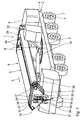
- the Fig. 1 and 2 show the mobile telescopic crane 1 in the intended state for driving.
- the boom 9 is in a fully retracted transport position.
- the locking units 42, 47 and 48 are unlocked and the boom sections 11 to 13 telescoped.
- the sub-arms 17 and 18 are completely lowered by means of the hydraulic cylinders 40, 41, so that the sub-boom 16 is arranged completely in the passage openings 38.
- the mobile telescopic crane 1 has the lowest possible total height, so that the maximum permitted height in the road is not exceeded.
- Fig. 2 illustrates the transport position of the boom 9 based on a cross section through the connecting element 29th
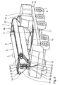
- Fig. 4 shows the mobile telescopic crane 1 in an operating position with the fully erected and austeleskop faced boom 9. In this state, which are associated with the connecting elements 29 and 30 Locking units 42, 47 and 48 also locked, so that the boom 9 has a high rigidity.
- Fig. 5 shows a cross section through the adjacent to the connecting element 29 locking units 47, 48th
- the boom 9 according to the invention has a high rigidity against bending forces perpendicular and parallel to the rocker plane W due to the high area moments of inertia. This can be achieved in relation to the weight of the boom 9, a significant load increase.
- no separate transport and no complex assembly is required compared to a conventional boom with guy supports.
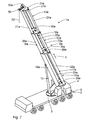
- Fig. 7 A second embodiment of the invention described.
- the sub-arms 17a, 18a are fixedly arranged on the sub-arm 16a by means of the connecting elements 28a to 31a and can not be displaced relative thereto. If this is the maximum allowable height of the mobile telescopic crane 1a is not exceeded, so a simplification of the structure of the boom 9a is possible.
- the mobile telescopic crane 1b has a boom 9b with three partial arms 16b, 17b and 18b, the partial boom 16b arranged in the rocking plane W having an oval cross-section.
- the connecting elements 28b to 31b accordingly have oval passage openings 38b.
- the cable guide channel 39b is formed in the connecting elements 28b to 31b above the sub-arm 16b.
- the sub-boom center longitudinal axis 33 of the sub-boom 16b extends at the intersection of the maximum height H 1 and the maximum width B 1 of the sub-boom 16b.
- the arranged in the rocker W partial boom 16b has a maximum width B 1 perpendicular to the rocker W and a maximum height H 1 in the rocker W, where: H 1 / B 1 > 1, in particular H 1 / B. 1 ⁇ 1.2, and in particular H 1 / B 1 ⁇ 1.5.
- the partial cross-sectional area A 1 is in each case larger than the partial cross-sectional area A 2 and A 3 .
- the boom 9b has in the region of the boom section 11b a maximum height H A , which results from the sum of H 1 and R 2 minus the overlap h 12 .
- the boom 9b in the region of the boom section 11b has a maximum width B A , which results from the sum R 2 , R 3 , b 2 and b 3 .
- the boom sections 12b and 13b wherein the outer radii R 2 and R 3 and the maximum height H 1 and the overlap h 12 due to the telescoping of the boom 9b are correspondingly smaller.
- the sub-arms 17b, 18b are arranged according to the second embodiment at a fixed distance to the sub-boom 16b.
- the sub-arms 17b, 18b according to the first embodiment may be displaceable relative to the sub-boom 16b.
- the hydraulic cylinder 14b for telescoping the boom 9b is disposed inside the sub-boom 16b.
- the locking units 47b, 48b are fastened directly to the connecting elements 29b, 30b, so that adjacent partial boom sections 22b and 23b, 23b and 24b, 25b and 26b and 26b and 27b are mechanically lockable to each other at the end.
- the locking units 47b, 48b each have two oppositely disposed locking pins 51b, which are feasible by respective associated locking holes 49, 50.
- the locking bolts 51b are hydraulically, pneumatically or electromechanically actuated, for example.
- the boom 9b has a high bending stiffness with respect to bending forces acting in the rocker plane W and bending forces acting perpendicularly to the rocker plane W. Due to its oval cross-section and its partial cross-sectional area A 1 , the sub-arm 16 b can, in particular, absorb high bending forces which act in the rocking plane W. With regard to the further structure and further operation of the mobile telescopic crane 1b, reference is made to the preceding embodiments.
- the features of the boom 9 to 9b are basically combined in any way to a boom according to the invention.
- the boom 9 to 9b invention further advantages over a conventional boom with guy supports.
- the booms 9 to 9b according to the invention can be optimized separately in each boom section 11 to 13b for the bending forces acting, so that they are received continuously along the boom 9 to 9b and not only at the end of the boom.
- both the transfer of the boom 9 to 9b in the operating position and their operation is extremely simple. In particular, no complex control of the biasing force of the guy ropes is required, whereby the operation is simplified and at the same time the reliability is increased, since no erroneous control of the biasing force is possible.
- the boom according to the invention allow 9 to 9b at a predefined weight a significant increase in load over conventional booms.
- a significantly easier handling of the boom 9 to 9b with respect to transport and installation or transfer to the operating position over conventional booms with guy supports is possible with the same load.
Landscapes
- Engineering & Computer Science (AREA)
- Mechanical Engineering (AREA)
- Jib Cranes (AREA)
Description
Die Erfindung betrifft einen Mobil-Teleskopkran gemäß dem Oberbegriff des Anspruchs 1.The invention relates to a mobile telescopic crane according to the preamble of claim 1.
Aus der
Aus der
Aus der
Der Erfindung liegt die Aufgabe zugrunde, einen Mobil-Teleskopkran zu schaffen, der auf einfache Weise eine Steigerung der Traglast ermöglicht.The invention has for its object to provide a mobile telescopic crane, which allows a simple way to increase the load.
Diese Aufgabe wird durch einen Mobil-Teleskopkran mit den Merkmalen des Anspruchs 1 gelöst. Indem der Ausleger aus mindestens drei im Abstand voneinander angeordneten und biegesteif miteinander verbundenen Teil-Auslegern aufgebaut ist, wird das Flächenträgheitsmoment des Auslegers deutlich erhöht. Das Flächenträgheitsmoment, das ein Maß für die Biegesteifigkeit ist, ergibt sich nach dem Satz von Steiner aus den Eigenanteilen der Teil-Ausleger sowie deren Steineranteilen. Durch die biegesteifen Verbindungselemente, die die Teil-Auslegerabschnitte der Teil-Ausleger zu Auslegerabschnitten verbinden, ist der Ausleger äußerst biegesteif, so dass die Querschnittsfläche bei Belastung des Auslegers im Wesentlichen eben bleibt, wodurch die Steineranteile bei der Berechnung des Flächenträgheitsmoments im Wesentlichen mit ihren theoretischen Werten, ggf. durch Abminderungsfaktoren reduziert, angesetzt werden können. Zudem wird in der ausgefahrenen Betriebsstellung des Auslegers eine hohe Steifigkeit durch die mechanische Verriegelung jeweils benachbarter Auslegerabschnitte erzielt, da die aus den Teil-Auslegerabschnitten aufgebauten Teil-Ausleger durch die Verriegelung äußerst biegesteif sind. Vorzugsweise sind jeweils benachbarte Teil-Auslegerabschnitte jedes Teil-Auslegers zueinander mechanisch verriegelbar. Die Verriegelung erfolgt beispielsweise mittels Verriegelungsbolzen, die hydraulisch, pneumatisch oder elektromechanisch betätigbar sind. Alternativ kann die Verriegelung mittels eines bajonettartigen Verriegelungsmechanismus erfolgen.This object is achieved by a mobile telescopic crane with the features of claim 1. By the boom of at least three spaced-apart and rigidly interconnected sub-arms is constructed, the area moment of inertia of the boom is significantly increased. The area moment of inertia, which is a measure of the bending stiffness, results, according to Steiner's theorem, from the own shares of the sub-cantilevers and their Steiner shares. Due to the rigid connecting elements that connect the sub-boom sections of the sub-boom to boom sections, the boom is extremely rigid, so that the cross-sectional area remains substantially flat under load of the boom, whereby the Steiner shares in the calculation of the area moment of inertia substantially with their theoretical Values, possibly reduced by reduction factors, can be applied. In addition, a high rigidity is achieved in the extended operating position of the boom by the mechanical locking of each adjacent boom sections, since the built-up of the sub-boom sections sub-arms are extremely rigid by the lock. Preferably, each adjacent sub-boom sections of each sub-boom are mechanically locked to each other. The locking takes place for example by means of locking bolts, which are hydraulically, pneumatically or electromechanically actuated. Alternatively, the locking can be done by means of a bayonet-type locking mechanism.
Durch die mindestens drei Teil-Ausleger wird eine hohe Steifigkeit des Auslegers sowohl gegenüber senkrecht zu der Wippebene als auch in der Wippebene wirkenden Biegekräften gewährleistet. Weist der Ausleger genau drei Teil-Ausleger auf, so können diese dreieckförmig angeordnet werden, wobei über die Breite und Höhe des Auslegers die Steifigkeit gegenüber senkrecht zu der Wippebene und in der Wippebene wirkenden Biegekräften einstellbar ist. Entsprechendes gilt, wenn der Ausleger mindestens vier, insbesondere genau vier Teil-Ausleger aufweist.By the at least three partial boom high rigidity of the boom is ensured both opposite to perpendicular to the rocker plane and acting in the rocker bending forces. If the jib has exactly three sub-jibs, then these jacks can be arranged in a triangular manner, whereby the stiffness can be adjusted over the width and height of the jib relative to the rocker plane perpendicular to the rocker plane and to bending forces acting in the rocker plane. The same applies if the boom has at least four, in particular exactly four sub-arms.
Aufgrund der deutlichen Steigerung des Flächenträgheitsmoments bzw. der Flächenträgheitsmomente kann der erfindungsgemäße Ausleger vollkommen anders dimensioniert werden als herkömmliche Ausleger, so dass im Vergleich zu einem herkömmlichen Ausleger mit Abspannstützen eine entsprechende Steigerung der Traglast mit einem geringeren Zusatzgewicht erzielbar ist. Indem die Teil-Ausleger aus in der Längsrichtung teleskopierbaren Teil-Auslegerabschnitten aufgebaut sind, kann der Ausleger mit geringem Aufwand von einer Transportstellung in eine Betriebsstellung gebracht werden. Durch das geringere Zusatzgewicht kann der erfindungsgemäße Mobil-Teleskopkran - innerhalb einer gewissen Traglastklasse - mit dem vollständigen Ausleger im öffentlichen Straßenverkehr zu der Baustelle fahren, so dass im Gegensatz zu einem Ausleger mit Abspannstützen kein separater Transport und keine aufwändige Montage erforderlich ist. Der erfindungsgemäße Mobil-Teleskopkran ermöglicht somit auf einfache Weise eine Steigerung der Traglast.Due to the significant increase in the area moment of inertia or the area moments of inertia of the boom according to the invention can be completely different dimensions than conventional boom, so that in comparison to a conventional boom with guy supports a corresponding increase in the load with a lower additional weight can be achieved. By the sub-arms are constructed of telescoping part-boom sections in the longitudinal direction, the boom can be brought from a transport position to an operating position with little effort. Due to the lower additional weight of the mobile telescopic crane according to the invention - drive within a certain load class - with the full boom on public roads to the site, so that in contrast to a boom with guy supports no separate transport and no complex installation is required. The inventive mobile telescopic crane thus enables a simple way to increase the load.
Darüber hinaus kann der erfindungsgemäße Ausleger derart dimensioniert werden, dass im Vergleich zu einem herkömmlichen Ausleger mit Abspannstützen nochmals eine erhebliche Steigerung der Traglast erzielbar ist. In diesem Fall hat auch der erfindungsgemäße Ausleger ein erhebliches Gewicht, so dass der Mobil-Teleskopkran mit dem erfindungsgemäßen Ausleger gegebenenfalls nicht mehr uneingeschränkt am öffentlichen Straßenverkehr teilnehmen kann. Einzelne Teil-Ausleger bzw. eine Gruppe von Teil-Auslegern oder der gesamte Ausleger müssen dann separat zu der Baustelle transportiert und dort montiert werden. Bei der beschriebenen Dimensionierung des erfindungsgemäßen Auslegers liegt der Vorteil somit in der Steigerung der Traglast.In addition, the boom according to the invention can be dimensioned such that in comparison with a conventional boom with guy supports again a significant increase in the load can be achieved is. In this case, the boom according to the invention also has a considerable weight, so that the mobile telescopic crane with the boom according to the invention may no longer be able to participate fully in public traffic. Individual sub-cantilevers or a group of sub-cantilevers or the entire boom must then be transported separately to the site and mounted there. In the described dimensioning of the boom according to the invention, the advantage is thus in the increase of the load.
Durch die Anzahl der Teil-Ausleger sowie deren Anordnung und Abstand zueinander sind eine Vielzahl von Optimierungsparametern gegeben, so dass der erfindungsgemäße Ausleger hinsichtlich seiner Biegesteifigkeit senkrecht zu und/oder parallel zu der Wippebene und/oder hinsichtlich des Gewichtes optimierbar ist. Je nachdem, in welcher Traglastklasse sich der erfindungsgemäße Mobil-Teleskopkran befinden soll, kann der erfindungsgemäße Ausleger in Bezug auf sein Gewicht und/oder in Bezug auf seine Biegesteifigkeit bzw. Traglast optimiert werden. Vorzugsweise weist der erfindungsgemäße Mobil-Teleskopkran einen Ausleger mit mindestens drei, insbesondere mindestens vier, und insbesondere mindestens fünf Auslegerabschnitten bzw. jeweiligen Teil-Auslegerabschnitten auf.By the number of sub-arms and their arrangement and distance from each other a variety of optimization parameters are given, so that the boom according to the invention can be optimized in terms of its bending stiffness perpendicular to and / or parallel to the rocker plane and / or in terms of weight. Depending on the load class in which the mobile telescopic crane according to the invention is to be located, the boom according to the invention can be optimized with regard to its weight and / or with regard to its bending stiffness or load capacity. The mobile telescopic crane according to the invention preferably has a boom with at least three, in particular at least four, and in particular at least five boom sections or respective partial boom sections.
Ein Mobil-Teleskopkran nach Anspruch 2 gewährleistet eine hohe Steifigkeit des Auslegers gegenüber Biegebelastungen. Die jeweilige Teil-Querschnittsfläche umfasst die Material-Querschnittsfläche sowie die von dem Material des Teil-Auslegers begrenzte Hohlraum-Querschnittsfläche.A mobile telescopic crane according to
Ein Mobil-Teleskopkran nach Anspruch 3 weist eine erhöhte Steifigkeit gegenüber senkrecht zu der Wippebene wirkenden Biegekräften auf. DieA mobile telescopic crane according to
Breite BA ist eine maximale Breite des Auslegers bzw. des jeweiligen Auslegerabschnitts.Width B A is a maximum width of the boom or of the respective boom section.
Ein Mobil-Teleskopkran nach Anspruch 4 weist eine erhöhte Steifigkeit gegenüber in der Wippebene wirkenden Biegekräften auf. Die Höhe HA ist eine maximale Höhe des Auslegers bzw. des jeweiligen Auslegerabschnitts.A mobile telescopic crane according to
Ein Mobil-Teleskopkran nach Anspruch 5 gewährleistet ein gleiches Steifigkeitsverhalten des Auslegers in positiver und negativer seitlicher Richtung.A mobile telescopic crane according to
Ein Mobil-Teleskopkran nach Anspruch 6 ermöglicht eine Optimierung der Steifigkeit des Auslegers im Verhältnis zu dessen Gewicht.A mobile telescopic crane according to
Ein Mobil-Teleskopkran nach Anspruch 7 gewährleistet eine kompakte Transportstellung des Auslegers. Durch die im Bedarfsfall mögliche Veränderung der Höhe des Auslegers wird insbesondere gewährleistet, dass der Mobil-Teleskopkran im Fahrbetrieb eine maximal zulässige Höhe nicht überschreitet. Die mindestens drei Teil-Ausleger können beispielsweise relativ zueinander linear verfahrbar oder verschwenkbar sein. Die Teil-Ausleger sind in einer verlagerten Betriebsstellung zueinander fixierbar. Dies erfolgt insbesondere mittels mechanischer Verriegelungseinheiten. Die mechanischen Verriegelungseinheiten sind beispielsweise an den Verbindungselementen angeordnet.A mobile telescopic crane according to
Ein Mobil-Teleskopkran nach Anspruch 8 gewährleistet eine Teleskopierbarkeit der Teil-Ausleger. Dadurch, dass in Längsrichtung benachbarte Teil-Auslegerabschnitte jeweils ineinander teleskopierbar sind bzw. teleskopierbar geführt sind, wird auf einfache Weise eine Teleskopierbarkeit der Auslegerabschnitte in Verbindung mit einer hohen Steifigkeit des Auslegers erzielt.A mobile telescopic crane according to
Ein Mobil-Teleskopkran nach Anspruch 9 ist einfach aufgebaut. Beispielsweise weisen die Teil-Auslegerabschnitte einen kreisförmigen Querschnitt auf.A mobile telescopic crane according to
Ein Mobil-Teleskopkran nach Anspruch 10 gewährleistet eine hohe Steifigkeit des Auslegers, sodass die Querschnittsfläche bei Belastung des Auslegers eben bleibt und die Steineranteile bei der Berechnung des Flächenträgheitsmoments annähernd mit ihren theoretischen Werten angesetzt werden können.A mobile telescopic crane according to
Ein Mobil-Teleskopkran nach Anspruch 11 ermöglicht auf einfache Weise eine mechanische Verriegelung benachbarter Teil-Auslegerabschnitte. Der jeweilige Verriegelungsbolzen ist beispielsweise hydraulisch, pneumatisch oder elektromechanisch betätigbar. Vorzugsweise sind alle benachbarten Teil-Auslegerabschnitte jedes Teil-Auslegers mittels mindestens eines Verriegelungsbolzens zueinander mechanisch verriegelbar. Weist der Ausleger genau drei Teil-Ausleger auf, so ist der in der Wippebene angeordnete Teil-Ausleger vorzugsweise von innen nach außen mechanisch verriegelbar, wohingegen die beabstandet zu der Wippebene angeordneten Teil-Ausleger vorzugsweise von außen nach innen mechanisch verriegelbar sind. Dies bedeutet, dass zwei benachbarte Teil-Auslegerabschnitte des in der Wippebene angeordneten Teil-Auslegers derart verriegelbar sind, dass der mindestens eine Verriegelungsbolzen zum Verriegeln zunächst durch den inneren Teil-Auslegerabschnitt und anschließend durch den äußeren Teil-Auslegerabschnitt geführt wird. Entsprechend umgekehrt wird bei benachbarten Teil-Auslegerabschnitten der beabstandet zu der Wippebene angeordneten Teil-Ausleger der mindestens eine Verriegelungsbolzen zunächst durch den äußeren Teil-Auslegerabschnitt und anschließend durch den inneren Teil-Auslegerabschnitt geführt.A mobile telescopic crane according to
Ein Mobil-Teleskopkran nach Anspruch 12 ermöglicht eine schnelle mechanische Verriegelung benachbarter Teil-Auslegerabschnitte. Jeder Verriegelungsbolzen muss lediglich durch zwei zugehörige Verriegelungsbohrungen der benachbarten Teil-Auslegerabschnitte geführt werden, um diese zueinander mechanisch zu verriegeln. Der zur Verriegelung zurückzulegende Weg des jeweiligen Verriegelungsbolzens ist gering. Dadurch, dass der jeweilige Verriegelungsbolzen nur durch zwei zugehörige Verriegelungsbohrungen geführt werden muss, ist eine vergleichsweise geringe Genauigkeit bei der Ausrichtung des jeweiligen Verriegelungsbolzens erforderlich. Vorzugsweise sind genau zwei Verriegelungsbolzen vorgesehen, die einander gegenüberliegend angeordnet sind und in entgegengesetzten Richtungen betätigbar sind.A mobile telescopic crane according to
Ein Mobil-Teleskopkran nach Anspruch 13 gewährleistest eine hohe Steifigkeit gegenüber senkrecht zu der Wippebene wirkenden Biegekräften. Würden die mindestens zwei Teil-Ausleger mit dem größten Abstand zu der Wippebene an einer dem Unterwagen zugewandten Unterseite des Auslegers angeordnet sein, sodass die Breite des Auslegers ausgehend von dessen Unterseite zu dessen Oberseite hin abnehmen würde, so würden die mindestens zwei unteren Teil-Ausleger sowohl aufgrund von in der Wippebene wirkenden Biegekräften als auch aufgrund von senkrecht zu der Wippebene wirkenden Biegekräften auf Druck belastet werden. Ein derartiger Aufbau des Auslegers würde aufgrund der zweifachen Druckbelastung gemäß den Eulerschen Knickfällen zu einer unerwünschten Traglastbeschränkung des Auslegers bzw. des Mobil-Teleskopkrans führen. Um dies zu vermeiden, werden die mindestens zwei Teil-Ausleger mit dem größten Abstand zu der Wippebene an der dem Unterwagen abgewandten Oberseite des Auslegers angeordnet, sodass in der Wippebene wirkende Biegekräfte im Wesentlichen zu einer Zugbelastung der mindestens zwei oberen Teil-Ausleger führen, wohingegen senkrecht zu der Wippebene wirkende Biegekräfte zu einer Druckbelastung eines der oberen Teil-Ausleger führen. Die Druckbelastung auf die am weitesten zu der Wippebene beabstandeten Teil-Ausleger kann somit deutlich reduziert werden. Das Flächenträgheitsmoment wird also einerseits in erfindungsgemäßer Weise erhöht, jedoch andererseits eine zweifache Druckbelastung vermieden. Durch die in Richtung zur Oberseite zunehmende Breite wird also eine optimale Biegesteifigkeit des Auslegers hinsichtlich senkrecht zu der Wippebene wirkender Biegekräfte erzielt. Da der Bauraum in der Transportstellung des Auslegers an der Oberseite im Wesentlichen nicht beschränkt ist, kann die Breite des Auslegers an der Oberseite in weiten Bereichen je nach Bedarf dimensioniert werden. Bei genau drei Teil-Auslegern ist ein dem Unterwagen zugewandter, unterer Teil-Ausleger in der Wippebene angeordnet und zwei dem Unterwagen abgewandte, obere Teil-Ausleger beabstandet zu der Wippebene angeordnet, sodass die Breite des Auslegers ausgehend von dem unteren Teil-Ausleger bzw. der Unterseite zu den oberen Teil-Auslegern bzw. der Oberseite hin zunimmt. Weist der Ausleger genau vier Teil-Ausleger auf, so sind diese trapezförmig angeordnet, sodass die Breite des Auslegers ausgehend von zwei dem Unterwagen zugewandten, unteren Teil-Auslegern zu zwei dem Unterwagen abgewandten, oberen Teil-Auslegern zunimmt. Die unteren Teil-Ausleger weisen somit einen geringeren Abstand zur Wippebene auf, als die oberen Teil-Ausleger. Da die Druckbelastung aufgrund senkrecht zu der Wippebene wirkender Biegekräfte mit dem Abstand zu der Wippebene abnimmt, wird auch bei einem Ausleger mit trapezförmig angeordneten Teil-Auslegern die Biegesteifigkeit hinsichtlich senkrecht zu der Wippebene wirkenden Biegekräften optimiert.A mobile telescopic crane according to
Ein Mobil-Teleskopkran nach Anspruch 14 weist einen verhältnismäßig steifen und einfach aufgebauten Ausleger auf.A mobile telescopic crane according to
Ein Mobil-Teleskopkran nach Anspruch 15 gewährleistet, dass der in der Wippebene angeordnete Teil-Ausleger entsprechend herkömmlichen Auslegern an dem Oberwagen angelenkt werden kann. Zusätzlich kann der in der Wippebene angeordnete Teil-Ausleger als Aufnahmeraum für den Hydraulikzylinder zum Teleskopieren des Auslegers dienen. Weiterhin kann der in der Wippebene angeordnete Teil-Ausleger aufgrund seiner Teil-Querschnittsfläche A1 hohe in der Wippebene wirkende Biegekräfte aufnehmen. Die Biegesteifigkeit des Auslegers ist somit entsprechend hoch. Für das Verhältnis der Teil-Querschnittsfläche A1 zu der Teil-Querschnittsfläche A2 bzw. A3 der weiteren Teil-Ausleger gilt: A1/Ai > 1, insbesondere A1/Ai ≥ 1,5, und insbesondere A1/Ai ≥ 2 mit i = 2 und 3. Vorzugsweise gilt A2 = A3.A mobile telescopic crane according to
Ein Mobil-Teleskopkran nach Anspruch 16 gewährleistet eine hohe Biegesteifigkeit des Auslegers gegenüber senkrecht zu der Wippebene wirkenden Biegekräften. Dadurch, dass ein dem Unterwagen zugewandter, unterer Teil-Ausleger in der Wippebene angeordnet ist und zwei dem Unterwagen abgewandte, obere Teil-Ausleger beabstandet zu der Wippebene angeordnet sind, nimmt die Breite des Auslegers von dem unteren Teil-Ausleger in Richtung der oberen Teil-Ausleger zu. Die Breite des Auslegers nimmt also von seiner Unterseite in Richtung zu der Oberseite zu. Der in der Wippebene angeordnete untere Teil-Ausleger wird im Wesentlichen nur aufgrund von in der Wippebene wirkenden Biegekräften auf Druck belastet. Senkrecht zu der Wippebene wirkende Biegekräfte führen in dem unteren Teil-Ausleger im Wesentlichen zu keinen Druckbelastungen. Demgegenüber werden die oberen und beabstandet zu der Wippebene angeordneten Teil-Ausleger aufgrund von in der Wippebene wirkenden Biegekräften im Wesentlichen nicht auf Druck belastet. Somit wird in allen Teil-Auslegern eine zweifache Druckbelastung aufgrund von in der Wippebene und senkrecht zu der Wippebene wirkenden Biegekräften vermieden. Durch die Anordnung der genau drei Teil-Ausleger wird somit einerseits das Flächenträgheitsmoment in erfindungsgemäßer Weise erhöht, jedoch andererseits eine zweifache Druckbelastung einzelner Teil-Ausleger aufgrund von in der Wippebene und senkrecht zu der Wippebene wirkenden Biegekräften vermieden, wodurch eine unerwünschte Beschränkung der Traglast gegeben sein würde. Dementsprechend wird durch die Anordnung der Teil-Ausleger die Biegesteifigkeit hinsichtlich senkrecht zu der Wippebene wirkenden Biegekräften optimiert. Der Abstand der oberen Teil-Ausleger zu der Wippebene ist bei Dimensionierung des Auslegers in weiten Bereichen variierbar, da insbesondere in der Transportstellung des Auslegers der Bauraum an der Oberseite des Auslegers nicht begrenzt ist.A mobile telescopic crane according to
Ein Mobil-Teleskopkran nach Anspruch 17 gewährleistet ein gleiches Steifigkeitsverhalten des Auslegers in positiver und negativer seitlicher Richtung. Weiterhin ist der Ausleger einfach aufgebaut.A mobile telescopic crane according to
Ein Mobil-Teleskopkran nach Anspruch 18 ermöglicht eine optimale Auslegung des unteren Teil-Auslegers hinsichtlich in der Wippebene wirkenden Biegekräften. Der Ausleger ermöglicht aufgrund des Querschnitts des unteren Teil-Auslegers eine im Vergleich zu herkömmlichen Auslegern höhere Biegesteifigkeit gegenüber in der Wippebene wirkenden Biegekräften. Insbesondere die Druckbelastbarkeit des unteren Teil-Auslegers wird durch die Form des Querschnitts im Vergleich zu herkömmlichen Auslegern mit einem im Wesentlichen rechteckförmigen Querschnitt erheblich verbessert. Zudem kann durch den Querschnitt des unteren Teil-Auslegers das Gewicht des Auslegers optimiert werden. Vorzugsweise weist der untere Teil-Ausleger über die gesamte Teil-Querschnittsfläche einen kreisförmigen oder ovalen Querschnitt auf. Der Querschnitt kann jedoch, beispielsweise aus fertigungstechnischen oder funktionalen Gründen, abschnittsweise von einer kreisförmigen oder ovalen Querschnittsform abweichen. Beispielsweise kann der jeweilige Querschnitt abschnittsweise abgeflacht sein. Weist der untere Teil-Ausleger einen ovalen Querschnitt auf, so gilt für eine maximale Breite B1 senkrecht zu der Wippebene und eine maximale Höhe H1 in der Wippebene H1/B1 > 1, insbesondere H1/B1 ≥ 1,2, und insbesondere H1/B1 ≥ 1,5. Vorzugsweise überlappt der untere Teil-Ausleger in Richtung der Wippebene mit den oberen Teil-Auslegern.A mobile telescopic crane according to
Ein Mobil-Teleskopkran nach Anspruch 19 ermöglicht auf einfache und platzsparende Weise eine Teleskopierbarkeit des Auslegers.A mobile telescopic crane according to
Ein Mobil-Teleskopkran nach Anspruch 20 gewährleistet eine hohe Steifigkeit des Auslegers gegenüber senkrecht zu der Wippebene wirkenden Biegekräften. Durch die endseitige Verriegelung benachbarter Teil-Auslegerabschnitte der oberen Teil-Ausleger werden seitlich wirkende Biegekräfte unmittelbar in den gesamten Ausleger abgeleitet und von diesem aufgenommen. Dies wird insbesondere dadurch gewährleistet, dass der jeweils mindestens eine Verriegelungsbolzen unmittelbar an dem zugehörigen bzw. benachbarten Verbindungselement befestigt bzw. verschiebbar gelagert ist.A mobile telescopic crane according to
Ein Mobil-Teleskopkran nach Anspruch 21 ermöglicht eine einfache und platzsparende Seilführung.A mobile telescopic crane according to
Ein Mobil-Teleskopkran nach Anspruch 22 gewährleistet in üblicher Weise das Heben von Lasten mittels eines Tragseils. Das Tragseil ist von einem freien Ende des Auslegers zu einer am Oberwagen angeordneten Seilwinde geführt. Das Tragseil ist vorzugweise in dem Seilführungskanal geführt.A mobile telescopic crane according to
Weitere Merkmale, Vorteile und Einzelheiten der Erfmdung ergeben sich anhand der nachfolgenden Beschreibung mehrerer Ausführungsbeispiele. Es zeigen:
- Fig. 1
- eine perspektivische Ansicht eines Mobil-Teleskopkrans gemäß einem ersten Ausführungsbeispiel mit einem teleskopierbaren Ausleger aus drei Teil-Auslegern, der sich in einer Transportstellung befindet,
- Fig. 2
- einen Querschnitt durch den Ausleger in
Fig. 1 im Bereich eines Verbindungselements, - Fig. 3
- eine perspektivische Ansicht des Mobil-Teleskopkrans in
Fig. 1 mit dem sich in einer eingefahrenen Betriebsstellung befindlichen Ausleger, - Fig. 4
- eine perspektivische Ansicht des Mobil-Teleskopkrans in
Fig. 1 mit dem sich in einer ausgefahrenen Betriebsstellung befindlichen Ausleger, - Fig. 5
- einen Querschnitt durch den Ausleger in
Fig. 4 im Bereich vor dem Verbindungselement, - Fig. 6
- einen Querschnitt durch den ausgefahrenen Ausleger in
Fig. 5 im Bereich eines ersten Auslegerabschnitts zur Veranschaulichung der Anordnung der Teil-Ausleger, - Fig. 7
- eine perspektivische Ansicht eines Mobil-Teleskopkrans gemäß einem zweiten Ausführungsbeispiel mit einem aus drei Teil-Auslegern aufgebauten Ausleger, der sich in einer ausgefahrenen Betriebsstellung befindet,
- Fig. 8
- eine perspektivische Ansicht eines Mobil-Teleskopkrans gemäß einem dritten Ausführungsbeispiel mit einem aus drei Teil-Auslegern aufgebauten Ausleger, der sich in einer Transportstellung befindet,
- Fig. 9
- eine perspektivische Ansicht des Mobil-Teleskopkrans in
Fig. 8 mit dem sich in einer ausgefahrenen Betriebsstellung befindlichen Ausleger, - Fig. 10
- eine Seitenansicht des Mobil-Teleskopkrans in
Fig. 9 , - Fig. 11
- einen Querschnitt durch den Ausleger in
Fig. 10 entlang der Schnittlinie XI-XI, und - Fig. 12
- einen Querschnitt durch den Ausleger in
Fig. 10 entlang der Schnittlinie XII-XII.
- Fig. 1
- a perspective view of a mobile telescopic crane according to a first embodiment with a telescopic boom of three sub-arms, which is in a transport position,
- Fig. 2
- a cross section through the boom in
Fig. 1 in the region of a connecting element, - Fig. 3
- a perspective view of the mobile telescopic crane in
Fig. 1 with the boom in a retracted operating position, - Fig. 4
- a perspective view of the mobile telescopic crane in
Fig. 1 with the boom in an extended operating position, - Fig. 5
- a cross section through the boom in
Fig. 4 in the area in front of the connecting element, - Fig. 6
- a cross section through the extended boom in
Fig. 5 in the region of a first boom section to illustrate the arrangement of the sub-boom, - Fig. 7
- a perspective view of a mobile telescopic crane according to a second embodiment with a built-up of three sub-arms boom, which is in an extended operating position,
- Fig. 8
- a perspective view of a mobile telescopic crane according to a third embodiment with a built-up of three sub-arms boom, which is in a transport position,
- Fig. 9
- a perspective view of the mobile telescopic crane in
Fig. 8 with the boom in an extended operating position, - Fig. 10
- a side view of the mobile telescopic crane in
Fig. 9 . - Fig. 11
- a cross section through the boom in
Fig. 10 along the section line XI-XI, and - Fig. 12
- a cross section through the boom in
Fig. 10 along the section line XII-XII.
Nachfolgend wird unter Bezugnahme auf die
Auf dem Oberwagen 3 ist ein Ausleger 9 angeordnet, der mittels eines Hydraulikzylinders 10 in einer Wippebene W verschwenkbar und in einer Längsrichtung L teleskopierbar ist. Der Ausleger 9 weist hierzu drei Auslegerabschnitte 11 bis 13 auf, die mittels eines Hydraulikzylinders 14 ein - und austeleskopierbar sind und so von einer eingefahrenen Transportstellung in eine ausgefahrene Betriebsstellung überführbar sind. Der erste Auslegerabschnitt 11 ist endseitig um eine horizontale Schwenkachse 15 verschwenkbar an dem Oberwagen 3 angelenkt. Das Verschwenken des Auslegers 9 in der Wippebene W erfolgt mittels des Hydraulikzylinders 10, der ausgehend von dem Oberwagen 3 beabstandet zu der Schwenkachse 15 an dem Auslegerabschnitt 11 angelenkt ist.On the
Der Ausleger 9 weist drei Teil-Ausleger 16, 17, 18 auf, die jeweils teleskopierbar aus drei Teil-Auslegerabschnitten 19 bis 21, 22 bis 24 und 25 bis 27 aufgebaut sind. Der Hydraulikzylinder 14 ist innerhalb eines Aufnahmeraums des Teil-Auslegers 16 angeordnet, der zur Ausbildung des Aufnahmeraums als Hohlzylinders ausgebildet ist. Die Teil-Ausleger 16 bis 18 sind quer zu der Längsrichtung L im Abstand voneinander angeordnet und durch vier biegesteife Verbindungselemente 28 bis 31 miteinander verbunden. Die Verbindungselemente 28 und 29 sind jeweils endseitig an den Teil-Auslegerabschnitten 19, 22 und 25 angeordnet und bilden mit diesen den ersten Auslegerabschnitt 11. Das Verbindungselement 30 ist wiederum an dem dem ersten Auslegerabschnitt 11 abgewandten Ende der Teil-Auslegerabschnitte 20, 23 und 26 angeordnet und bildet mit diesen den zweiten Auslegerabschnitt 12. Entsprechend ist das Verbindungselement 31 an einem dem zweiten Auslegerabschnitt 12 abgewandten Ende der Teil-Auslegerabschnitte 21, 24 und 27 angeordnet und bildet mit diesen den dritten Auslegerabschnitt 13.The
Der Ausleger 9 ist asymmetrisch zu der Wippebene W aufgebaut und weist eine als Schwerlinie bezeichnete und in der Wippebene W liegende Ausleger-Mittellängsachse 32 auf. Die Teil-Ausleger 16 bis 18 weisen entsprechend zugehörige Teil-Ausleger-Mittellängsachsen 33 bis 35 auf, die polygonförmig bzw. dreieckförmig und symmetrisch zu der Wippebene W angeordnet sind. Die Mittellängsachsen 32 und 33 liegen in der Wippebene W und weisen senkrecht zu der Wippebene W einen Abstand b1 = 0 und parallel zu der Wippebene W einen Abstand h1 voneinander auf. Demgegenüber weisen die Mittellängsachsen 34 und 35 gleiche Abstände b2 und b3 senkrecht von der Wippebene W auf. Weiterhin weisen die Mittellängsachsen 34, 35 zu der Mittellängsachse 32 einen Abstand h2 und h3 parallel zu der Wippebene W auf.The
Der in der Wippebene W angeordnete und dem Unterwagen 2 zugewandte, untere Teil-Ausleger 16 bildet somit eine Unterseite des Auslegers 9, wohingegen die beabstandet zu der Wippebene W angeordneten und dem Unterwagen 2 abgewandten, oberen Teil-Ausleger 17, 18 eine Oberseite des Auslegers 9 bilden. Der Ausleger 9 weist senkrecht zu der Wippebene W eine Breite B auf, die ausgehend von dem unteren Teil-Ausleger 16 in Richtung der oberen Teil-Ausleger 17, 18 bis zu einer maximalen Breite BA zunimmt. Dies ist in
Die Teil-Auslegerabschnitte 19 bis 27 sind als Hohlzylinder ausgebildet und weisen einen kreisförmigen Querschnitt auf.
Für das Verhältnis der Breite BA zu jeder der Breiten Bi mit i = 1 bis 3 gilt: BA/Bi ≥ 1,5, insbesondere BA/Bi ≥ 2, und insbesondere BA/Bi ≥ 2,5. Weiterhin gilt für das Verhältnis der Höhe HA zu jeder der Höhen Hi mit i = 1 bis 3: HA/Hi ≥ 1,2, insbesondere HA/Hi ≥ 1,5, insbesondere HA/Hi ≥ 2, und insbesondere HA/Hi ≥ 2,5. Entsprechendes gilt für die Auslegerabschnitte 12 und 13.For the ratio of the width B A to each of the widths B i with i = 1 to 3, B A / B i ≥ 1.5, in particular B A / B i ≥ 2, and in particular B A / B i ≥ 2, 5th Furthermore, for the ratio of the height H A to each of the heights H i with i = 1 to 3: H A / H i ≥ 1.2, in particular H A / H i ≥ 1.5, in particular H A / H i ≥ 2, and in particular H A / H i ≥ 2.5. The same applies to the
Die Auslegerabschnitte 19, 22 und 25 weisen senkrecht zu der Wippebene W Teil-Querschnittsflächen A1, A2 und A3 auf, die sich jeweils aus der Kreisfläche mit dem zugehörigen Außenradius R1, R2 und R3 ergeben. Die Teil-Querschnittsflächen Ai umfassen somit jeweils die zugehörigen Material-Querschnittsflächen AMi sowie die von dem Material begrenzten Hohlraum-Querschnittsflächen AHi, wobei i = 1 bis 3 gilt. Durch die beabstandete Anordnung der Teil-Ausleger 16, 17 und 18 bzw. der Teil-Auslegerabschnitte 19, 22 und 25 weist der Ausleger 9 im Bereich des Auslegerabschnitts 11 eine Querschnittsfläche AA auf, die größer als eine Summe AS der Teil-Querschnittsflächen A1 bis A3 ist. Die Querschnittsfläche AA ist in
Für das Verhältnis der Querschnittsfläche AA zu der Summe AS der Teil-Querschnittsflächen A1 bis A3 gilt: AA/AS > 1, insbesondere AA/AS ≥ 1,5, insbesondere AA/AS ≥ 2, insbesondere AA/AS ≥ 2,5, insbesondere AA/AS ≥ 3, und insbesondere AA/AS ≥ 4. Entsprechendes gilt für die Auslegerabschnitte 12 und 13, wobei zu berücksichtigen ist, dass die Teil-Auslegerabschnitte 20, 23, 26 bzw. 21, 24, 27 aufgrund der Teleskopierbarkeit entsprechend geringere Radien R1, R2 und R3 aufweisen.For the ratio of the cross-sectional area A A to the sum A S of the partial cross-sectional areas A 1 to A 3, the following applies: A A / A S > 1, in particular A A / A S ≥ 1.5, in particular A A / A S ≥ 2 , in particular A A / A S ≥ 2.5, in particular A A / A S ≥ 3, and in particular A A / A S ≥ 4. The same applies to the
Durch diesen Aufbau weist der Ausleger 9 im Vergleich zu herkömmlichen Auslegern ein höheres Flächenträgheitsmoment Iz,ges bzw. Iy,ges in Bezug auf senkrecht zu der Wippebene W und in der Wippebene W wirkende Biegekräfte auf. Das Flächenträgheitsmoment Iz,ges bezüglich senkrecht zu der Wippebene W wirkenden Biegekräften, also bei einer Biegung um die z-Achse, ergibt sich zu: 
wobei
i ein Laufindex für die Teil-Ausleger ist,
Iz,i der Eigenanteil des Teil-Auslegers i ist,
bi der Abstand der Schwerlinie bzw. Mittellängsachse des Teil-Auslegers i von der Schwerlinie bzw. Mittellängsachse des Auslegers in y-Richtung ist, AMi die Material-Querschnittsfläche des Teil-Auslegers i ist,
bi 2 · AMi der Steineranteil des Teil-Auslegers i ist und n die Anzahl der Teil-Ausleger ist.By this construction, the
in which
i is a run index for the sub-arms,
I z, i is the intrinsic portion of the sub-cantilever i,
b i is the distance of the center of gravity of the sub-cantilever i from the center of gravity of the cantilever in the y-direction, A Mi is the material cross-sectional area of the sub-cantilever i,
b i 2 · A Mi is the stone fraction of the sub-boom i and n is the number of sub-beams.
Für die Gleichung (1) gilt zudem n = 3 und b1 = 0. Gleichung (1) beschreibt das erzielbare Flächenträgheitsmoment Iz,ges bei einem ideal biegesteifen Ausleger 9. Bei der praktischen Dimensionierung des Auslegers 9 ist ein Abminderungsfaktor α bei den Steineranteilen zu berücksichtigen, der von der Anzahl der Verbindungselemente 28 bis 31 sowie deren Biegesteifigkeitsgrad abhängt.Equation (1) also describes n = 3 and b 1 = 0. Equation (1) describes the achievable area moment of inertia I z, ges for an ideally
Entsprechend ergibt sich das Flächenträgheitsmoment Iy,ges bezüglich parallel zu der Wippebene W wirkenden Biegekräften, also bei einer Biegung um die y-Achse, zu: 
wobei
i ein Laufindex für die Teil-Ausleger ist,
Iy,i der Eigenanteil des Teil-Auslegers i ist,
hi der Abstand der Schwerlinie bzw. Mittellängsachse des Teil-Auslegers i von der Schwerlinie bzw. Mittellängsachse des Auslegers in z-Richtung ist,
AMi die Material-Querschnittsfläche des Teil-Auslegers i ist,
hi 2 · AMi der Steineranteil des Teil-Auslegers i ist und
n die Anzahl der Teil-Ausleger ist.Correspondingly, the area moment of inertia I y, ges results with respect to bending forces acting parallel to the rocker plane W, that is to say with a bend about the y-axis, to:
in which
i is a run index for the sub-arms,
I y, i is the intrinsic portion of the sub-cantilever i,
h i is the distance of the center of gravity or center longitudinal axis of the sub-boom i from the center of gravity or the center longitudinal axis of the boom in the z-direction,
A Mi is the material cross-sectional area of the sub-cantilever i,
h i 2 · A Mi is the Steiner portion of the sub-boom i and
n is the number of sub-arms.
Entsprechend zu Gleichung (1) ist bei Gleichung (2) bei den Steineranteilen ein Abminderungsfaktor β zu berücksichtigen.Corresponding to equation (1), an attenuation factor β must be taken into account in equation (2) for the Steiner shares.
Die Flächenträgheitsmomente stellen ein Maß für die Steifigkeit des Auslegers 9 gegenüber den jeweiligen Biegekräften dar. Aufgrund der Steineranteile werden die Flächenträgheitsmomente gegenüber herkömmlichen Auslegern erheblich erhöht.The area moments of inertia provide a measure of the rigidity of the
Die Verbindungselemente 28 bis 31 sind im Wesentlichen als dreieckförmige Platten ausgebildet und weisen jeweils zwei Durchführungsöffnungen 36, 37 für die Teil-Auslegerabschnitte 22 bis 27 der Teil-Ausleger 12 und 13 auf. Ferner weisen die Verbindungselemente 28 bis 31 jeweils eine rechteckförmige Durchführungsöffnung 38 für die Teil-Auslegerabschnitte 19 bis 21 des Teil-Auslegers 16 auf, die ungefähr bis zu den Mittellängsachsen 34, 35 reicht. Die Durchführungsöffnungen 38 bilden somit in den Verbindungselementen 28 bis 31 einen Seilführungskanal 39 zur Führung eines Tragseils 52 aus. Das Tragseil 52 ist in üblicher Weise von dem freien Ende des Auslegers 9 zu einer am Oberwagen 3 angeordneten Seilwinde 53 geführt. Das Tragseil 52 ist am freien Ende des Auslegers 9 über zwei Umlenkrollen 54, 55 geführt, die mittels eines Traggestells 56 an dem freien Ende des Auslegers 9 drehbar gelagert sind.The connecting
Die Teil-Ausleger 17 und 18 sind relativ zu dem Teil-Ausleger 16 parallel zu der Wippebene W verlagerbar. Hierzu sind an dem dem Oberwagen 3 zugewandten Ende beidseitig des Teil-Auslegerabschnitts 19 zwei Hydraulikzylinder 40 fest an diesem angeordnet und mit dem Verbindungselement 28 verbunden. Entsprechend sind endseitig an dem Teil-Auslegerabschnitt 19 zwei Hydraulikzylinder 41 befestigt, die mit dem Verbindungselement 29 verbunden sind. Zur Verlagerung der Teil-Ausleger 17, 18 bzw. zur Fixierung dieser Teil-Ausleger 17, 18 relativ zu dem Teil-Ausleger 16 sind Verriegelungseinheiten 42 vorgesehen. Die Verriegelungseinheiten 42 sind in die Teil-Auslegerabschnitte 19 bis 21 und die zugehörigen Verbindungselemente 28 bis 31 integriert. Die
Durch die Hydraulikzylinder 40, 41 und die Verriegelungseinheiten 42 ist der Ausleger 9 von einer Transportstellung in eine Betriebsstellung und umgekehrt überführbar. In der Transportstellung ist die Querschnittsfläche AA bzw. die Höhe HA des Auslegers 9 im Vergleich zu der Betriebsstellung vermindert, wodurch der Mobil-Teleskopkran 1 eine geringere Gesamthöhe aufweist. Die Verminderung der Gesamthöhe ist beispielsweise erforderlich, um eine im Straßenverkehr maximal zulässige Höhe nicht zu überschreiten.By the
Zusätzlich weisen die zu den Verbindungselementen 29 und 30 gehörigen Verriegelungseinheiten 42 Verriegelungsbohrungen 46 auf, durch die die Verriegelungsbolzen 44 ebenfalls führbar sind. Die Verriegelungsbohrungen 46 sind jeweils in dem inneren Teil-Auslegerabschnitt 20 bzw. 21 ausgebildet, so dass im verriegelten Zustand die benachbarten Teil-Auslegerabschnitte 19 und 20 bzw. 20 und 21 in der Längsrichtung L verriegelt sind.In addition, the locking
Zur Verriegelung in der Längsrichtung L sind weiterhin Verriegelungseinheiten 47 und 48 vorgesehen, die im Bereich der Verbindungselemente 29 und 30 angeordnet sind. Die Verriegelungseinheiten 47 und 48 sind unmittelbar an dem jeweils zugehörigen Verbindungselement 29 bzw. 30 gelagert bzw. befestigt. Die Verriegelungseinheiten 47, 48 weisen jeweils Verriegelungsbohrungen 49, 50 auf, die in den benachbarten Teil-Auslegerabschnitten 22 und 23, 23 und 24, 25 und 26 sowie 26 und 27 ausgebildet sind. Durch die Verriegelungsbohrungen 49, 50 ist jeweils ein Verriegelungsbolzen 51 führbar, so dass die gewünschte mechanische Verriegelung der Auslegerabschnitte 11 und 12 sowie 12 und 13 erzielbar ist. Alternativ können entsprechend zu den Verriegelungseinheiten 42 zwei Verriegelungsbolzen 51 vorgesehen sein, die einander gegenüberliegend angeordnet sind und in jeweils zugehörige Verriegelungsbohrungen 49, 50 verlagerbar sind. Die Verriegelungsbolzen 51 sind beispielsweise hydraulisch, pneumatisch oder elektromechanisch betätigbar.For locking in the longitudinal direction L further locking
Die
Die
Daraufhin wird der Ausleger 9 mittels des Hydraulikzylinders 10 in der Wippebene W aufgerichtet und mittels des Hydraulikzylinders 14 austeleskopiert.
Der erfindungsgemäße Ausleger 9 weist aufgrund der hohen Flächenträgheitsmomente eine hohe Steifigkeit gegenüber Biegekräften senkrecht und parallel zu der Wippebene W auf. Hierdurch kann im Verhältnis zu dem Gewicht des Auslegers 9 eine erhebliche Traglaststeigung erzielt werden. Insbesondere weist der Ausleger 9 auch ohne Gewichtszunahme gegenüber herkömmlichen Auslegern bzw. bei einer nur geringen Gewichtszunahme eine deutliche Traglaststeigerung auf, die ungefähr der eines herkömmlichen Auslegers mit Abspannstützen entspricht. Jedoch ist gegenüber einem herkömmlichen Ausleger mit Abspannstützen kein separater Transport und keine aufwändige Montage erforderlich.The
Nachfolgend ist anhand von
Nachfolgend ist anhand der
Der in der Wippebene W angeordnete Teil-Ausleger 16b weist eine maximale Breite B1 senkrecht zu der Wippebene W und eine maximale Höhe H1 in der Wippebene W auf, wobei gilt: H1/B1 > 1, insbesondere H1/B1 ≥ 1,2, und insbesondere H1/B1 ≥ 1,5. Der Teil-Ausleger 16b überlappt in Richtung der Wippebene W mit den Teil-Auslegern 17b, 18b mit einem Überlappungsmaß h12 bzw. h13, wobei gilt h12 = h13. Weiterhin gilt h12 < R2 und h13 < R3. Die Teil-Querschnittsfläche A1 ist jeweils größer als die Teil-Querschnittsfläche A2 und A3. Vorzugsweise gilt A1/A2 ≥ 1,5, insbesondere A1/A2 ≥ 2, und insbesondere A1/A2 ≥ 2,5. Entsprechendes gilt für A1/A3. Der Ausleger 9b weist im Bereich des Auslegerabschnitts 11b eine maximale Höhe HA auf, die sich aus der Summe von H1 und R2 abzüglich des Überlappungsmaßes h12 ergibt. Weiterhin weist der Ausleger 9b im Bereich des Auslegerabschnitts 11b eine maximale Breite BA auf, die sich aus der Summe R2, R3, b2 und b3 ergibt. Entsprechendes ergibt sich für die Auslegerabschnitte 12b und 13b, wobei die Außenradien R2 und R3 sowie die maximale Höhe H1 sowie das Überlappungsmaß h12 aufgrund der Teleskopierbarkeit des Auslegers 9b entsprechend kleiner sind.The arranged in the rocker W
Die Teil-Ausleger 17b, 18b sind entsprechend dem zweiten Ausführungsbeispiel in einem festen Abstand zu dem Teil-Ausleger 16b angeordnet. Alternativ können die Teil-Ausleger 17b, 18b entsprechend dem ersten Ausführungsbeispiel relativ zu dem Teil-Ausleger 16b verlagerbar sein. Der Hydraulikzylinder 14b zum Teleskopieren des Auslegers 9b ist innerhalb des Teil-Auslegers 16b angeordnet.The sub-arms 17b, 18b are arranged according to the second embodiment at a fixed distance to the sub-boom 16b. Alternatively, the sub-arms 17b, 18b according to the first embodiment may be displaceable relative to the sub-boom 16b. The
Die Verriegelungseinheiten 47b, 48b sind unmittelbar an den Verbindungselementen 29b, 30b befestigt, sodass benachbarte Teil-Auslegerabschnitte 22b und 23b, 23b und 24b, 25b und 26b sowie 26b und 27b endseitig zueinander mechanisch verriegelbar sind. Die Verriegelungseinheiten 47b, 48b weisen jeweils zwei gegenüberliegend angeordnete Verriegelungsbolzen 51b auf, die durch jeweils zugehörige Verriegelungsbohrungen 49, 50 führbar sind. Die Verriegelungsbolzen 51b sind beispielsweise hydraulisch, pneumatisch oder elektromechanisch betätigbar.The locking
Der Ausleger 9b weist eine hohe Biegesteifigkeit hinsichtlich in der Wippebene W wirkender Biegekräfte und senkrecht zu der Wippebene W wirkender Biegekräfte auf. Der Teil-Ausleger 16b kann aufgrund seines ovalen Querschnitts und seiner Teil-Querschnittsfläche A1 insbesondere hohe Biegekräfte aufnehmen, die in der Wippebene W wirken. Hinsichtlich des weiteren Aufbaus und der weiteren Funktionsweise des Mobil-Teleskopkrans 1b wird auf die vorangegangenen Ausführungsbeispiele verwiesen.The
Die Merkmale der Ausleger 9 bis 9b sind grundsätzlich in beliebiger Weise zu einem erfindungsgemäßen Ausleger kombinierbar. Neben der einfachen Steigerung der Traglast durch Erhöhung der Flächenträgheitsmomente weisen die erfindungsgemäßen Ausleger 9 bis 9b weitere Vorteile gegenüber einem herkömmlichen Ausleger mit Abspannstützen auf. Die erfindungsgemäßen Ausleger 9 bis 9b sind in jedem Auslegerabschnitt 11 bis 13b separat auf die wirkenden Biegekräfte optimierbar, so dass diese kontinuierlich entlang des Auslegers 9 bis 9b und nicht nur am Ende des Auslegers aufgenommen werden. Darüber hinaus ist sowohl die Überführung der Ausleger 9 bis 9b in die Betriebsstellung als auch deren Betrieb äußerst einfach. Insbesondere ist keine aufwändige Steuerung der Vorspannkraft der Abspannseile erforderlich, wodurch der Betrieb vereinfacht und gleichzeitig die Zuverlässigkeit erhöht wird, da keine Fehlsteuerung der Vorspannkraft möglich ist. Über die Anzahl der Teil-Ausleger 16 bis 17b sowie deren Anordnung und Abstand zueinander, wodurch die Querschnittsfläche AA definiert wird, sowie über die Querschnittsform und die Teil-Querschnittsflächen Ai sind eine Vielzahl von Optimierungsparametern gegeben, wodurch ein erfindungsgemäßer Ausleger 9 bis 9b hinsichtlich der Aufnahmefähigkeit von senkrecht zu und in der Wippebene W wirkenden Biegekräften und hinsichtlich des Gewichtes optimiert werden kann. Insgesamt ermöglichen die erfindungsgemäßen Ausleger 9 bis 9b bei vordefiniertem Gewicht eine erhebliche Steigerung der Traglast gegenüber herkömmlichen Auslegern. Insbesondere ist bei gleicher Traglast eine erheblich einfachere Handhabung der Ausleger 9 bis 9b in Bezug auf Transport und Montage bzw. Überführung in die Betriebsstellung gegenüber herkömmlichen Auslegern mit Abspannstützen möglich.The features of the
Claims (22)
- Mobile telescopic crane with- a movable undercarriage (2),- a superstructure (3) rotatably arranged on the undercarriage (2),- a jib (9; 9a; 9b), which is telescopic in a longitudinal direction, arranged on the superstructure (3) and is pivotable in a luffing plane, characterised
in that the telescopic jib (9; 9a; 9b) has at least three part-jibs (16 to 18; 16a to 18a; 16b to 18b),
in that each of the part-jibs (16 to 18; 16a to 18a; 16b to 18b) is constructed from at least two part-jib portions (19 to 27; 19a to 27a; 19b to 27b) so as to be telescopic in the longitudinal direction,
in that part-jib portions (19 to 27; 19a to 27a; 19b to 27b) arranged at a spacing from one another transverse to the longitudinal direction each form a jib portion (11 to 13; 11a to 13a; 11b to 13b) with at least one flexurally rigid connecting element (28 to 31; 28a to 31a; 28b to 31b), and
in that respective adjacent jib portions (11 to 13; 11a to 13a; 11b to 13b) are mechanically lockable with respect to one another in the longitudinal direction. - Mobile telescopic crane according to claim 1, characterised in that the jib (9; 9a; 9b), perpendicular to the luffing plane, has a cross-sectional area AA produced by the at least three part-jibs (16 to 18; 16a to 18a; 16b to 18b) and each of the part-jibs (16 to 18; 16a to 18a; 16b to 18b), perpendicular to the luffing plane, has a part-cross-sectional area (A1 to A3), wherein there applies to a ratio of the cross-sectional area AA to a sum AS of the part-cross-sectional areas: AA/AS> 1, in particular AA/AS ≥ 1.5, in particular AA/AS ≥ 2, and, in particular AA/AS ≥ 2.5.
- Mobile telescopic crane according to claim 1 or 2, characterised in that the jib (9; 9a; 9b), perpendicular to the luffing plane, has a width BA and each of the part-jibs (16 to 18; 16a to 18a; 16b to 18b) has a width Bi, to the ratio of which there applies, in each case: BA/Bi ≥ 1.5, in particular BA/Bi ≥ 2, and, in particular BA/Bi ≥ 2.5.
- Mobile telescopic crane according to any one of claims 1 to 3, characterised
in that the jib (9; 9a; 9b), parallel to the luffing plane, has a height HA and each of the part-jibs (16 to 18; 16a to 18a; 16b to 18b) has a height Hi, to the ratio of which there applies, in each case: HA/Hi ≥ 1.2, in particular HA/Hi ≥ 1.5, in particular HA/Hi ≥ 2, and in particular HA/Hi ≥ 2.5. - Mobile telescopic crane according to any one of claims 1 to 4, characterised
in that the part-jibs (16 to 18; 16a to 18a; 16b to 18b) are arranged symmetrically with respect to the luffing plane. - Mobile telescopic crane according to any one of claims 1 to 5, characterised
in that the part-jibs (16 to 18; 16a to 18a; 16b to 18b) are arranged polygonally, in particular triangularly, with respect to one another. - Mobile telescopic crane according to any one of claims 1 to 6, characterised
in that at least one part-jib (17, 18) is displaceable to change the cross-sectional area AA, in particular to change a height HA of the jib (9), with respect to at least one other part-jib (16). - Mobile telescopic crane according to any one of claims 1 to 7, characterised
in that the part-jib portions (19 to 27; 19a to 27a; 19b to 27b) of all the part-jibs (16 to 18; 16a to 18a; 16b to 18b) are configured as hollow cylinders and adjacent part-jib portions (19 to 27; 19a to 27a; 19b to 27b) are in each case telescopeable into one another. - Mobile telescopic crane according to any one of claims 1 to 8, characterised
in that the part-jib portions (19 to 27; 19a to 27a) of all the part-jibs (16 to 18; 16a to 18a) have a geometrically similar and, in particular, an identical cross-section. - Mobile telescopic crane according to any one of claims 1 to 9, characterised
in that respective adjacent part-jib portions (19 to 27; 19a to 27a; 19b to 27b) of all the part-jibs (16 to 18; 16a to 18a; 16b to 18b) are mechanically lockable with respect to one another in the longitudinal direction. - Mobile telescopic crane according to any one of claims 1 to 10, characterised
in that at least two adjacent part-jib portions (19 to 27; 19a to 27a; 19b to 27b) are mechanically lockable with respect to one another by means of at least one locking bolt (44, 51; 44b, 51b). - Mobile telescopic crane according to any one of claims 1 to 11, characterised
in that at least two adjacent part-jib portions (19 to 21; 19a to 21a; 19b to 27b) are mechanically lockable with respect to one another by means of at least two locking bolts (44; 44b, 51b). - Mobile telescopic crane according to any one of claims 1 to 12, characterised
in that the jib (9; 9a; 9b) has a width that changes perpendicular to the luffing plane, the width increasing proceeding from at least one lower part-jib (16; 16a; 16b) facing the undercarriage (2) up to at least two upper part-jibs (17, 18; 17a, 18a; 17b, 18b) remote from the undercarriage (2). - Mobile telescopic crane according to any one of claims 1 to 13, characterised
in that the jib (9; 9a; 9b) has precisely three part-jibs (16 to 18; 16a to 18a; 16b to 18b), which are arranged triangularly and symmetrically with respect to the luffing plane. - Mobile telescopic crane according to claim 14, characterised in that the part-jib (16; 16a; 16b) arranged in the luffing plane has a larger part-cross-sectional area (A1) in comparison to the further part-jibs (17, 18; 17a, 18a; 17b, 18b).
- Mobile telescopic crane according to claim 14 or 15, characterised in that the part-jib (16; 16a; 16b) arranged in the luffing plane is arranged on a lower side and the part-jibs (17, 18; 17a, 18a; 17b, 18b) arranged spaced apart from the luffing plane are arranged on an upper side of the jib (9; 9a; 9b).
- Mobile telescopic crane according to any one of claims 14 to 16, characterised
in that the part-jibs (17, 18; 17a, 18a; 17b, 18b) arranged spaced apart from the luffing plane have the same, in particular circular, cross-sections and the same part-cross-sectional areas (A2, A3). - Mobile telescopic crane according to any one of claims 14 to 17, characterised
in that the part-jib (16; 16a; 16b) arranged in the luffing plane has a cross-section, at least in portions, which is selected from the group circular and oval. - Mobile telescopic crane according to any one of claims 14 to 18, characterised
in that the part-jib (9; 9a; 9b) arranged in the luffing plane forms a receiving space, in which a hydraulic cylinder (14; 14b) is arranged to telescope the jib (9; 9a; 9b). - Mobile telescopic crane according to any one of claims 14 to 19, characterised
in that respective adjacent part-jib portions (22 to 27; 22a to 27a; 22b to 27b) of the part-jibs (17, 18; 17a, 18a; 17b, 18b) arranged spaced apart from the luffing plane are mechanically lockable with respect to one another at the end, in particular the at least one locking bolt (51, 51b) provided in each case to lock adjacent part-jib portions (22 to 27;
22a to 27a; 22b to 27b) being arranged on the associated connecting element (29, 30; 29a, 30a; 29b, 30b). - Mobile telescopic crane according to any one of claims 1 to 20, characterised
in that the part-jibs (16 to 18; 16a to 18a; 16b to 18b) limit a cable guide channel (39; 39b). - Mobile telescopic crane according to any one of claims 1 to 21, characterised
in that a support cable (52) is guided along the jib (9; 9a; 9b), the support cable (52) being arranged, in particular, in the cable guide channel (39; 39b).
Applications Claiming Priority (2)
| Application Number | Priority Date | Filing Date | Title |
|---|---|---|---|
| DE102010063456 | 2010-12-17 | ||
| PCT/EP2011/073018 WO2012080452A1 (en) | 2010-12-17 | 2011-12-16 | Mobile telescopic crane |
Publications (2)
| Publication Number | Publication Date |
|---|---|
| EP2504267A1 EP2504267A1 (en) | 2012-10-03 |
| EP2504267B1 true EP2504267B1 (en) | 2013-07-10 |
Family
ID=45350773
Family Applications (2)
| Application Number | Title | Priority Date | Filing Date |
|---|---|---|---|
| EP11797252.1A Active EP2651812B1 (en) | 2010-12-17 | 2011-12-16 | Mobile telescopic crane |
| EP11797251.3A Active EP2504267B1 (en) | 2010-12-17 | 2011-12-16 | Mobile telescopic crane |
Family Applications Before (1)
| Application Number | Title | Priority Date | Filing Date |
|---|---|---|---|
| EP11797252.1A Active EP2651812B1 (en) | 2010-12-17 | 2011-12-16 | Mobile telescopic crane |
Country Status (7)
| Country | Link |
|---|---|
| US (2) | US9637358B2 (en) |
| EP (2) | EP2651812B1 (en) |
| JP (2) | JP5953315B2 (en) |
| CN (2) | CN103261083B (en) |
| DE (1) | DE202011110230U1 (en) |
| RU (2) | RU2547492C2 (en) |
| WO (2) | WO2012080452A1 (en) |
Cited By (2)
| Publication number | Priority date | Publication date | Assignee | Title |
|---|---|---|---|---|
| DE102016114837A1 (en) | 2016-08-10 | 2018-02-15 | Terex Global Gmbh | Telescopic boom with guy system for a mobile crane and guying system |
| DE102017101113B3 (en) | 2017-01-20 | 2018-07-12 | Terex Global Gmbh | Telescopic boom with pole tensioning system for a mobile crane and guying method |
Families Citing this family (19)
| Publication number | Priority date | Publication date | Assignee | Title |
|---|---|---|---|---|
| WO2012080452A1 (en) * | 2010-12-17 | 2012-06-21 | Tadano Faun Gmbh | Mobile telescopic crane |
| CN103043541B (en) * | 2012-12-31 | 2015-09-16 | 大连理工大学 | Two box type telescopic arm configuration |
| CN103754757A (en) * | 2013-08-22 | 2014-04-30 | 柳州柳工叉车有限公司 | Telescopic arm lifting hook |
| JP6223071B2 (en) * | 2013-08-30 | 2017-11-01 | 株式会社タダノ | Boom telescopic mechanism of crane equipment |
| DE202014004976U1 (en) * | 2014-06-16 | 2014-08-07 | Liebherr-Werk Ehingen Gmbh | Telescopic boom and crane |
| JP6531505B2 (en) * | 2015-06-11 | 2019-06-19 | 株式会社タダノ | Telescopic boom mounting structure |
| CA172264S (en) * | 2016-12-21 | 2017-07-11 | John Rene Spronken | Crane base |
| US10662719B2 (en) | 2017-01-30 | 2020-05-26 | National Oilwell Varco, L.P. | Telescopic deployment mast |
| CN107686062B (en) * | 2017-08-02 | 2019-06-11 | 中建三局集团有限公司 | A kind of self-elevating tower crane of variable-angle |
| KR101945522B1 (en) | 2017-08-18 | 2019-02-07 | 삼성중공업 주식회사 | Multistage Crane |
| DE102017127973A1 (en) | 2017-11-27 | 2019-05-29 | Liebherr-Werk Ehingen Gmbh | Telescopic boom for a crane and crane with a corresponding telescopic boom |
| US10746349B2 (en) * | 2018-01-15 | 2020-08-18 | Hamaye Co | Extendable cage telescopic system |
| CN108502723B (en) * | 2018-03-30 | 2019-09-10 | 山东建筑大学 | The method and system of crane arm vibration is eliminated when crane rotation and luffing movement |
| US11118372B2 (en) * | 2018-06-05 | 2021-09-14 | The Will-Burt Company | Auto-locking telescoping mast |
| DE102019002039A1 (en) * | 2019-03-22 | 2020-09-24 | David Mann | Lifting device |
| DE102019110505B3 (en) * | 2019-03-29 | 2020-06-18 | Liebherr-Werk Ehingen Gmbh | Telescopic boom and mobile crane |
| US11300284B2 (en) | 2019-05-07 | 2022-04-12 | Kore Infrastructure | Production of renewable fuel for steam generation for heavy oil extraction |
| RU2720039C1 (en) * | 2019-07-19 | 2020-04-23 | Федеральное государственное бюджетное образовательное учреждение высшего образования "Тихоокеанский государственный университет" | Hydraulic excavator working equipment |
| CN110371840B (en) * | 2019-08-06 | 2020-06-02 | 庄俊 | Lifting supporting beam with adjustable length |
Family Cites Families (35)
| Publication number | Priority date | Publication date | Assignee | Title |
|---|---|---|---|---|
| US3494593A (en) * | 1968-01-29 | 1970-02-10 | Schlumberger Technology Corp | Portable mast |
| JPS4728652Y1 (en) | 1969-02-15 | 1972-08-29 | ||
| US3610433A (en) * | 1970-05-07 | 1971-10-05 | Baker Equipment Eng Co | Hydraulically operable extendable boom |
| DE2103570C3 (en) * | 1971-01-26 | 1974-03-07 | Leo Gottwald Kg, 4000 Duesseldorf | Telescopic crane boom in frame construction |
| US3752261A (en) * | 1971-06-21 | 1973-08-14 | S Bushnell | Multi-stage lift |
| US3802136A (en) * | 1972-01-26 | 1974-04-09 | Gottwald Kg Leo | Extendible crane boom formed of telescopic box-shaped sections |
| AT338849B (en) * | 1975-06-10 | 1977-09-12 | Voest Ag | BRINGING DEVICE FOR METALLURGICAL DRESSERS |
| US4238911A (en) * | 1978-09-29 | 1980-12-16 | Frosch Robert A | Telescoping columns |
| FI802255A (en) | 1979-07-25 | 1981-01-26 | Coles Cranes Ltd | BOM FOER LYFTKRAN |
| US4327533A (en) * | 1980-08-13 | 1982-05-04 | Kidde, Inc. | Crane boom extending, retracting and cooperative latching arrangement |
| US4590720A (en) * | 1984-02-06 | 1986-05-27 | Parco Mast And Substructure, Inc. | Telescoping derrick |
| US5101215A (en) * | 1985-05-10 | 1992-03-31 | Chu Associates, Inc. | Telescoping lightweight antenna tower assembly and the like |
| US5060427A (en) * | 1990-02-01 | 1991-10-29 | Kidde Industries, Inc. | Extension and retraction system for four section telescopic boom having simultaneous and equal extension and retraction of the telescopic sections |
| SE501102C2 (en) * | 1993-04-26 | 1994-11-14 | Hiab Ab | Extendable crane arm |
| RU2106295C1 (en) * | 1996-04-03 | 1998-03-10 | Николай Егорович Храмов | Boom of high load capacity truck crane |
| JP4010466B2 (en) | 1997-07-03 | 2007-11-21 | オックスジャッキ株式会社 | Heavy equipment jack equipment |
| DE10022658B4 (en) | 1999-06-28 | 2007-10-04 | Terex-Demag Gmbh & Co. Kg | telescopic crane |
| US7077209B2 (en) * | 2001-10-30 | 2006-07-18 | Varco/Ip, Inc. | Mast for handling a coiled tubing injector |
| US6726437B2 (en) * | 2002-02-08 | 2004-04-27 | Clark Equipment Company | Telescoping loader lift arm |
| GB2387373A (en) | 2002-04-12 | 2003-10-15 | Bamford Excavators Ltd | Composite boom for a load handling machine |
| JP4728652B2 (en) | 2005-01-25 | 2011-07-20 | 株式会社リコー | 3D CAD data detail concealment device, 3D CAD data detail concealment method, and 3D CAD data detail concealment program |
| US7430890B1 (en) * | 2005-06-24 | 2008-10-07 | Vincent P Battaglia | Telescoping tower and method of manufacture |
| JP2007276918A (en) | 2006-04-04 | 2007-10-25 | Nippon Kiki Kogyo Kk | Elevator |
| US7574832B1 (en) * | 2007-01-24 | 2009-08-18 | Lieberman Phillip L | Portable telescoping tower assembly |
| CA2697304A1 (en) * | 2007-09-05 | 2009-03-12 | Palfinger Ag | Profile shape for a crane boom |
| US8234823B2 (en) * | 2008-07-09 | 2012-08-07 | Mcclure Clifton D | Telescoping mast |
| US8046970B2 (en) * | 2009-04-03 | 2011-11-01 | Aluma Tower Company, Inc. | Unguyed telescoping tower |
| CN101955133B (en) * | 2009-07-14 | 2013-06-05 | 三一汽车制造有限公司 | Movable crane |
| RU2418735C1 (en) * | 2010-01-12 | 2011-05-20 | Павел Владимирович Корчагин | Lifting crane system |
| CA2736718A1 (en) * | 2010-04-09 | 2011-10-09 | Electro Mechanical Industries, Inc. | Tower structure |
| DE102010020016B4 (en) * | 2010-05-10 | 2021-04-29 | Liebherr-Werk Ehingen Gmbh | Crane and method of erecting the crane |
| WO2012080452A1 (en) * | 2010-12-17 | 2012-06-21 | Tadano Faun Gmbh | Mobile telescopic crane |
| US20140059949A1 (en) * | 2012-09-06 | 2014-03-06 | Said Lounis | Telescopic multi-mast system |
| US8955264B2 (en) * | 2013-04-24 | 2015-02-17 | Solaris Technologies, Inc. | Portable tower with improved guiding and lifting systems |
| US9371662B1 (en) * | 2015-03-31 | 2016-06-21 | Us Tower Corporation | Variable height telescoping lattice tower |
-
2011
- 2011-12-16 WO PCT/EP2011/073018 patent/WO2012080452A1/en active Application Filing
- 2011-12-16 CN CN201180060696.1A patent/CN103261083B/en active Active
- 2011-12-16 JP JP2013543808A patent/JP5953315B2/en active Active
- 2011-12-16 US US13/994,377 patent/US9637358B2/en active Active
- 2011-12-16 RU RU2013125915/11A patent/RU2547492C2/en active
- 2011-12-16 WO PCT/EP2011/073024 patent/WO2012080455A1/en active Application Filing
- 2011-12-16 US US13/994,383 patent/US9376292B2/en active Active
- 2011-12-16 DE DE202011110230U patent/DE202011110230U1/en not_active Expired - Lifetime
- 2011-12-16 JP JP2013543806A patent/JP5934717B2/en active Active
- 2011-12-16 EP EP11797252.1A patent/EP2651812B1/en active Active
- 2011-12-16 EP EP11797251.3A patent/EP2504267B1/en active Active
- 2011-12-16 CN CN201180060629.XA patent/CN103269970B/en active Active
- 2011-12-16 RU RU2013125916/11A patent/RU2548652C2/en active
Cited By (5)
| Publication number | Priority date | Publication date | Assignee | Title |
|---|---|---|---|---|
| DE102016114837A1 (en) | 2016-08-10 | 2018-02-15 | Terex Global Gmbh | Telescopic boom with guy system for a mobile crane and guying system |
| WO2018029306A1 (en) | 2016-08-10 | 2018-02-15 | Terex Global Gmbh | Telescoping jib comprising a guying system for a mobile crane and guying method therefor |
| US11174137B2 (en) | 2016-08-10 | 2021-11-16 | Tadano Demag Gmbh | Telescoping jib comprising a guying system for a mobile crane and guying method therefor |
| DE102017101113B3 (en) | 2017-01-20 | 2018-07-12 | Terex Global Gmbh | Telescopic boom with pole tensioning system for a mobile crane and guying method |
| WO2018134249A1 (en) | 2017-01-20 | 2018-07-26 | Terex Global Gmbh | Telescoping jib comprising a rod guying system for a mobile crane and guying method therefor |
Also Published As
| Publication number | Publication date |
|---|---|
| JP2013545691A (en) | 2013-12-26 |
| RU2547492C2 (en) | 2015-04-10 |
| US20150008206A1 (en) | 2015-01-08 |
| JP2013545690A (en) | 2013-12-26 |
| CN103261083B (en) | 2015-04-29 |
| DE202011110230U1 (en) | 2013-02-13 |
| WO2012080455A1 (en) | 2012-06-21 |
| EP2504267A1 (en) | 2012-10-03 |
| US9637358B2 (en) | 2017-05-02 |
| WO2012080452A1 (en) | 2012-06-21 |
| JP5953315B2 (en) | 2016-07-20 |
| US20140158657A1 (en) | 2014-06-12 |
| US9376292B2 (en) | 2016-06-28 |
| RU2548652C2 (en) | 2015-04-20 |
| RU2013125916A (en) | 2015-01-27 |
| CN103261083A (en) | 2013-08-21 |
| EP2651812A1 (en) | 2013-10-23 |
| CN103269970A (en) | 2013-08-28 |
| CN103269970B (en) | 2015-04-29 |
| RU2013125915A (en) | 2015-01-27 |
| JP5934717B2 (en) | 2016-06-15 |
| EP2651812B1 (en) | 2014-12-03 |
Similar Documents
| Publication | Publication Date | Title |
|---|---|---|
| EP2504267B1 (en) | Mobile telescopic crane | |
| DE102009016033B4 (en) | Lattice boom and lattice boom | |
| EP3040303B1 (en) | Crane and lattice mast section for a lattice mast of a crane of this type | |
| DE102011016015B4 (en) | Lattice boom crane and lattice boom | |
| DE102009020338A1 (en) | Telescopic crane with self-assembling guying fixture and mounting method for a guying fixture | |
| WO2014147047A1 (en) | Lattice-mast element, lattice-mast jib having at least one such lattice-mast element, and crane having at least one such lattice-mast jib | |
| DE10128986A1 (en) | Mobile crane has load increasing device permanently connected to main jib part and with individual weight of telescopic extensions each reduced to avoid exceeding maximum permissible weight without having to reduce number of extensions | |
| AT523305B1 (en) | Mobile crane | |
| DE102011115355A1 (en) | Boom element for telescopic boom, particularly telescopic shot or telescopic boom base section for construction vehicle, particularly mobile crane, comprises bowl-shaped corner posts and lattice bars | |
| DE102014012661B4 (en) | Method of operating a crane and crane | |
| DE102018116575A1 (en) | Support for the rear guy line of a telescopic crane | |
| DE102012023814B4 (en) | Folding tip for a mobile crane and method for pivoting the folding top | |
| DE102012210112B3 (en) | Mobile telescopic crane comprises telescopic arm with three sub-arms, where lower sub-arm faces undercarriage and two upper sub-arms are turned away from undercarriage and are hinged to undercarriage, and sub-arm is made of sub-arm sections | |
| DE102020129454B4 (en) | Mobile crane with a boom system | |
| DE202008009281U1 (en) | crane | |
| DE102012210110B3 (en) | Method for start-up of mobile telescopic crane, involves forming extension arm portions by partial extension portions arranged at distance to each other with bending-resistant connectors, and latching partial arm portions of lower arm | |
| DE102012210109B3 (en) | Mobile telescopic crane has rigid connection elements that are provided with cantilever portions respectively, and upper sub-arms that are faced away from wheeled undercarriage and are partially formed using fiber composite material | |
| EP1541520B1 (en) | Mobile crane | |
| DE4337415C2 (en) | Crane, especially a large mobile crane | |
| DE102022128653A1 (en) | Mobile crane with lattice boom, lattice boom and method for assembling such a crane | |
| DE202022104596U1 (en) | Connection section for an additional boom of a mobile crane and mobile crane herewith | |
| DE102022117472B4 (en) | Auxiliary tip for the boom of a working device | |
| DE102022122282A1 (en) | Mobile crane with a detachable attached superstructure and setup process for this | |
| DE10226319B4 (en) | Mobile crane with retractable and extendable coupling device for a counterweight | |
| DE202015000719U1 (en) | Uppercarriage for a crane or a construction machine |
Legal Events
| Date | Code | Title | Description |
|---|---|---|---|
| REG | Reference to a national code |
Ref country code: DE Ref legal event code: R138 Ref document number: 502011001026 Country of ref document: DE Free format text: GERMAN DOCUMENT NUMBER IS 502011001026 Ref country code: DE Ref legal event code: R138 Ref document number: 202011110230 Country of ref document: DE Free format text: GERMAN DOCUMENT NUMBER IS 502011001026 |
|
| PUAI | Public reference made under article 153(3) epc to a published international application that has entered the european phase |
Free format text: ORIGINAL CODE: 0009012 |
|
| 17P | Request for examination filed |
Effective date: 20120625 |
|
| AK | Designated contracting states |
Kind code of ref document: A1 Designated state(s): AL AT BE BG CH CY CZ DE DK EE ES FI FR GB GR HR HU IE IS IT LI LT LU LV MC MK MT NL NO PL PT RO RS SE SI SK SM TR |
|
| REG | Reference to a national code |
Ref country code: DE Ref legal event code: R079 Ref document number: 502011001026 Country of ref document: DE Free format text: PREVIOUS MAIN CLASS: B66C0023260000 Ipc: B66C0023360000 |
|
| GRAP | Despatch of communication of intention to grant a patent |
Free format text: ORIGINAL CODE: EPIDOSNIGR1 |
|
| DAX | Request for extension of the european patent (deleted) | ||
| RIC1 | Information provided on ipc code assigned before grant |
Ipc: B66C 23/70 20060101ALI20130211BHEP Ipc: B66C 23/36 20060101AFI20130211BHEP |
|
| GRAS | Grant fee paid |
Free format text: ORIGINAL CODE: EPIDOSNIGR3 |
|
| GRAA | (expected) grant |
Free format text: ORIGINAL CODE: 0009210 |
|
| AK | Designated contracting states |
Kind code of ref document: B1 Designated state(s): AL AT BE BG CH CY CZ DE DK EE ES FI FR GB GR HR HU IE IS IT LI LT LU LV MC MK MT NL NO PL PT RO RS SE SI SK SM TR |
|
| REG | Reference to a national code |
Ref country code: GB Ref legal event code: FG4D Free format text: NOT ENGLISH |
|
| REG | Reference to a national code |
Ref country code: CH Ref legal event code: EP Ref country code: AT Ref legal event code: REF Ref document number: 620873 Country of ref document: AT Kind code of ref document: T Effective date: 20130715 |
|
| REG | Reference to a national code |
Ref country code: IE Ref legal event code: FG4D Free format text: LANGUAGE OF EP DOCUMENT: GERMAN |
|
| REG | Reference to a national code |
Ref country code: DE Ref legal event code: R096 Ref document number: 502011001026 Country of ref document: DE Effective date: 20130905 |
|
| PG25 | Lapsed in a contracting state [announced via postgrant information from national office to epo] |
Ref country code: SI Free format text: LAPSE BECAUSE OF FAILURE TO SUBMIT A TRANSLATION OF THE DESCRIPTION OR TO PAY THE FEE WITHIN THE PRESCRIBED TIME-LIMIT Effective date: 20130710 |
|
| REG | Reference to a national code |
Ref country code: NL Ref legal event code: VDEP Effective date: 20130710 |
|
| REG | Reference to a national code |
Ref country code: LT Ref legal event code: MG4D |
|
| PG25 | Lapsed in a contracting state [announced via postgrant information from national office to epo] |
Ref country code: LT Free format text: LAPSE BECAUSE OF FAILURE TO SUBMIT A TRANSLATION OF THE DESCRIPTION OR TO PAY THE FEE WITHIN THE PRESCRIBED TIME-LIMIT Effective date: 20130710 Ref country code: HR Free format text: LAPSE BECAUSE OF FAILURE TO SUBMIT A TRANSLATION OF THE DESCRIPTION OR TO PAY THE FEE WITHIN THE PRESCRIBED TIME-LIMIT Effective date: 20130710 Ref country code: CY Free format text: LAPSE BECAUSE OF FAILURE TO SUBMIT A TRANSLATION OF THE DESCRIPTION OR TO PAY THE FEE WITHIN THE PRESCRIBED TIME-LIMIT Effective date: 20130911 Ref country code: PT Free format text: LAPSE BECAUSE OF FAILURE TO SUBMIT A TRANSLATION OF THE DESCRIPTION OR TO PAY THE FEE WITHIN THE PRESCRIBED TIME-LIMIT Effective date: 20131111 Ref country code: SE Free format text: LAPSE BECAUSE OF FAILURE TO SUBMIT A TRANSLATION OF THE DESCRIPTION OR TO PAY THE FEE WITHIN THE PRESCRIBED TIME-LIMIT Effective date: 20130710 Ref country code: IS Free format text: LAPSE BECAUSE OF FAILURE TO SUBMIT A TRANSLATION OF THE DESCRIPTION OR TO PAY THE FEE WITHIN THE PRESCRIBED TIME-LIMIT Effective date: 20131110 Ref country code: NO Free format text: LAPSE BECAUSE OF FAILURE TO SUBMIT A TRANSLATION OF THE DESCRIPTION OR TO PAY THE FEE WITHIN THE PRESCRIBED TIME-LIMIT Effective date: 20131010 |
|
| PG25 | Lapsed in a contracting state [announced via postgrant information from national office to epo] |
Ref country code: LV Free format text: LAPSE BECAUSE OF FAILURE TO SUBMIT A TRANSLATION OF THE DESCRIPTION OR TO PAY THE FEE WITHIN THE PRESCRIBED TIME-LIMIT Effective date: 20130710 Ref country code: NL Free format text: LAPSE BECAUSE OF FAILURE TO SUBMIT A TRANSLATION OF THE DESCRIPTION OR TO PAY THE FEE WITHIN THE PRESCRIBED TIME-LIMIT Effective date: 20130710 Ref country code: ES Free format text: LAPSE BECAUSE OF FAILURE TO SUBMIT A TRANSLATION OF THE DESCRIPTION OR TO PAY THE FEE WITHIN THE PRESCRIBED TIME-LIMIT Effective date: 20131021 Ref country code: GR Free format text: LAPSE BECAUSE OF FAILURE TO SUBMIT A TRANSLATION OF THE DESCRIPTION OR TO PAY THE FEE WITHIN THE PRESCRIBED TIME-LIMIT Effective date: 20131011 Ref country code: FI Free format text: LAPSE BECAUSE OF FAILURE TO SUBMIT A TRANSLATION OF THE DESCRIPTION OR TO PAY THE FEE WITHIN THE PRESCRIBED TIME-LIMIT Effective date: 20130710 Ref country code: PL Free format text: LAPSE BECAUSE OF FAILURE TO SUBMIT A TRANSLATION OF THE DESCRIPTION OR TO PAY THE FEE WITHIN THE PRESCRIBED TIME-LIMIT Effective date: 20130710 |
|
| PG25 | Lapsed in a contracting state [announced via postgrant information from national office to epo] |
Ref country code: CY Free format text: LAPSE BECAUSE OF FAILURE TO SUBMIT A TRANSLATION OF THE DESCRIPTION OR TO PAY THE FEE WITHIN THE PRESCRIBED TIME-LIMIT Effective date: 20130710 |
|
| PG25 | Lapsed in a contracting state [announced via postgrant information from national office to epo] |
Ref country code: EE Free format text: LAPSE BECAUSE OF FAILURE TO SUBMIT A TRANSLATION OF THE DESCRIPTION OR TO PAY THE FEE WITHIN THE PRESCRIBED TIME-LIMIT Effective date: 20130710 Ref country code: DK Free format text: LAPSE BECAUSE OF FAILURE TO SUBMIT A TRANSLATION OF THE DESCRIPTION OR TO PAY THE FEE WITHIN THE PRESCRIBED TIME-LIMIT Effective date: 20130710 Ref country code: CZ Free format text: LAPSE BECAUSE OF FAILURE TO SUBMIT A TRANSLATION OF THE DESCRIPTION OR TO PAY THE FEE WITHIN THE PRESCRIBED TIME-LIMIT Effective date: 20130710 Ref country code: RO Free format text: LAPSE BECAUSE OF FAILURE TO SUBMIT A TRANSLATION OF THE DESCRIPTION OR TO PAY THE FEE WITHIN THE PRESCRIBED TIME-LIMIT Effective date: 20130710 Ref country code: SK Free format text: LAPSE BECAUSE OF FAILURE TO SUBMIT A TRANSLATION OF THE DESCRIPTION OR TO PAY THE FEE WITHIN THE PRESCRIBED TIME-LIMIT Effective date: 20130710 |
|
| PLBE | No opposition filed within time limit |
Free format text: ORIGINAL CODE: 0009261 |
|
| STAA | Information on the status of an ep patent application or granted ep patent |
Free format text: STATUS: NO OPPOSITION FILED WITHIN TIME LIMIT |
|
| 26N | No opposition filed |
Effective date: 20140411 |
|
| BERE | Be: lapsed |
Owner name: TADANO FAUN G.M.B.H. Effective date: 20131231 |
|
| REG | Reference to a national code |
Ref country code: DE Ref legal event code: R097 Ref document number: 502011001026 Country of ref document: DE Effective date: 20140411 |
|
| PG25 | Lapsed in a contracting state [announced via postgrant information from national office to epo] |
Ref country code: LU Free format text: LAPSE BECAUSE OF FAILURE TO SUBMIT A TRANSLATION OF THE DESCRIPTION OR TO PAY THE FEE WITHIN THE PRESCRIBED TIME-LIMIT Effective date: 20131216 |
|
| REG | Reference to a national code |
Ref country code: IE Ref legal event code: MM4A |
|
| PG25 | Lapsed in a contracting state [announced via postgrant information from national office to epo] |
Ref country code: BE Free format text: LAPSE BECAUSE OF NON-PAYMENT OF DUE FEES Effective date: 20131231 Ref country code: IE Free format text: LAPSE BECAUSE OF NON-PAYMENT OF DUE FEES Effective date: 20131216 |
|
| PG25 | Lapsed in a contracting state [announced via postgrant information from national office to epo] |
Ref country code: MC Free format text: LAPSE BECAUSE OF FAILURE TO SUBMIT A TRANSLATION OF THE DESCRIPTION OR TO PAY THE FEE WITHIN THE PRESCRIBED TIME-LIMIT Effective date: 20130710 |
|
| PG25 | Lapsed in a contracting state [announced via postgrant information from national office to epo] |
Ref country code: SM Free format text: LAPSE BECAUSE OF FAILURE TO SUBMIT A TRANSLATION OF THE DESCRIPTION OR TO PAY THE FEE WITHIN THE PRESCRIBED TIME-LIMIT Effective date: 20130710 |
|
| PG25 | Lapsed in a contracting state [announced via postgrant information from national office to epo] |
Ref country code: HU Free format text: LAPSE BECAUSE OF FAILURE TO SUBMIT A TRANSLATION OF THE DESCRIPTION OR TO PAY THE FEE WITHIN THE PRESCRIBED TIME-LIMIT; INVALID AB INITIO Effective date: 20111216 Ref country code: RS Free format text: LAPSE BECAUSE OF FAILURE TO SUBMIT A TRANSLATION OF THE DESCRIPTION OR TO PAY THE FEE WITHIN THE PRESCRIBED TIME-LIMIT Effective date: 20131010 Ref country code: MK Free format text: LAPSE BECAUSE OF FAILURE TO SUBMIT A TRANSLATION OF THE DESCRIPTION OR TO PAY THE FEE WITHIN THE PRESCRIBED TIME-LIMIT Effective date: 20130710 Ref country code: BG Free format text: LAPSE BECAUSE OF FAILURE TO SUBMIT A TRANSLATION OF THE DESCRIPTION OR TO PAY THE FEE WITHIN THE PRESCRIBED TIME-LIMIT Effective date: 20130710 |
|
| REG | Reference to a national code |
Ref country code: CH Ref legal event code: PL |
|
| PG25 | Lapsed in a contracting state [announced via postgrant information from national office to epo] |
Ref country code: MT Free format text: LAPSE BECAUSE OF FAILURE TO SUBMIT A TRANSLATION OF THE DESCRIPTION OR TO PAY THE FEE WITHIN THE PRESCRIBED TIME-LIMIT Effective date: 20130710 |
|
| PG25 | Lapsed in a contracting state [announced via postgrant information from national office to epo] |
Ref country code: LI Free format text: LAPSE BECAUSE OF NON-PAYMENT OF DUE FEES Effective date: 20141231 Ref country code: CH Free format text: LAPSE BECAUSE OF NON-PAYMENT OF DUE FEES Effective date: 20141231 |
|
| REG | Reference to a national code |
Ref country code: FR Ref legal event code: PLFP Year of fee payment: 5 |
|
| PG25 | Lapsed in a contracting state [announced via postgrant information from national office to epo] |
Ref country code: TR Free format text: LAPSE BECAUSE OF FAILURE TO SUBMIT A TRANSLATION OF THE DESCRIPTION OR TO PAY THE FEE WITHIN THE PRESCRIBED TIME-LIMIT Effective date: 20130710 |
|
| REG | Reference to a national code |
Ref country code: FR Ref legal event code: PLFP Year of fee payment: 6 |
|
| REG | Reference to a national code |
Ref country code: FR Ref legal event code: PLFP Year of fee payment: 7 |
|
| PG25 | Lapsed in a contracting state [announced via postgrant information from national office to epo] |
Ref country code: AL Free format text: LAPSE BECAUSE OF FAILURE TO SUBMIT A TRANSLATION OF THE DESCRIPTION OR TO PAY THE FEE WITHIN THE PRESCRIBED TIME-LIMIT Effective date: 20130710 |
|
| P01 | Opt-out of the competence of the unified patent court (upc) registered |
Effective date: 20230530 |
|
| PGFP | Annual fee paid to national office [announced via postgrant information from national office to epo] |
Ref country code: GB Payment date: 20231220 Year of fee payment: 13 |
|
| PGFP | Annual fee paid to national office [announced via postgrant information from national office to epo] |
Ref country code: IT Payment date: 20231228 Year of fee payment: 13 Ref country code: FR Payment date: 20231221 Year of fee payment: 13 Ref country code: DE Payment date: 20231214 Year of fee payment: 13 Ref country code: AT Payment date: 20231221 Year of fee payment: 13 |