RU2106295C1 - Boom of high load capacity truck crane - Google Patents
Boom of high load capacity truck crane Download PDFInfo
- Publication number
- RU2106295C1 RU2106295C1 RU96107357A RU96107357A RU2106295C1 RU 2106295 C1 RU2106295 C1 RU 2106295C1 RU 96107357 A RU96107357 A RU 96107357A RU 96107357 A RU96107357 A RU 96107357A RU 2106295 C1 RU2106295 C1 RU 2106295C1
- Authority
- RU
- Russia
- Prior art keywords
- boom
- jib
- truck crane
- shunting
- base
- Prior art date
Links
- 239000000758 substrate Substances 0.000 claims description 4
- 244000261422 Lysimachia clethroides Species 0.000 abstract 2
- 239000000126 substance Substances 0.000 abstract 1
- 238000010276 construction Methods 0.000 description 2
- 230000008092 positive effect Effects 0.000 description 2
- 230000001364 causal effect Effects 0.000 description 1
- 230000008878 coupling Effects 0.000 description 1
- 238000010168 coupling process Methods 0.000 description 1
- 238000005859 coupling reaction Methods 0.000 description 1
- 210000001145 finger joint Anatomy 0.000 description 1
- 238000009434 installation Methods 0.000 description 1
- 230000003993 interaction Effects 0.000 description 1
- 238000005272 metallurgy Methods 0.000 description 1
- 239000003351 stiffener Substances 0.000 description 1
- 238000004642 transportation engineering Methods 0.000 description 1
Images

Landscapes
- Jib Cranes (AREA)
Abstract
Description
Изобретение относится к области подъемно-транспортного машиностроения, а более конкретно к монтажным автомобильным кранам повышенной грузоподъемности, на специальном базовом шасси автомобильного типа для контажа наземных стационарных сооружений. The invention relates to the field of hoisting and transport engineering, and more particularly to mounting automotive cranes of increased carrying capacity, on a special base chassis of an automobile type for the contour of land-based stationary structures.
Актуальность проблемы вызвана отсутствием отечественных высокоэффективных машин с повышенной грузоподъемностью, например, свыше 300 т на шасси автомобильного типа, хотя известно, что за рубежом в этом направлении работает ряд фирм: "Lana", Испания; "Тадана", Япония; "Lierherr", ФРГ и др. The urgency of the problem is caused by the lack of domestic high-performance machines with increased carrying capacity, for example, over 300 tons on an automobile-type chassis, although it is known that a number of companies work abroad in this direction: "Lana", Spain; Tadana, Japan; "Lierherr", Germany and others.
Известна подвижная опора стрелы, в которой один конец опорной стойки шарнирно соединен с оголовком стрелы, другой - с ползуном, подвижным вдоль опорной поверхности, выполненной в виде наклонно установленной рамы с изменяемым посредством силовых цилиндров углов наклона, причем ползун перемещается по опорной поверхности под действием домкрата. (Стреловые самоходные краны и строповка грузов. Справочник, М.: Металлургия, 1990, с.239, рис.5.15). A movable boom support is known in which one end of the support stand is pivotally connected to the boom head, the other to a slider movable along a support surface made in the form of an obliquely mounted frame with tilt angles that can be changed by means of power cylinders, and the slider moves along the support surface under the influence of a jack . (Jib self-propelled cranes and cargo slinging. Handbook, Moscow: Metallurgy, 1990, p.239, Fig. 5.15).
Недостатком этого технического решения является малая грузоподъемность и сложность в оборудовании, транспортировке и настройке в период подготовительных работ. The disadvantage of this technical solution is the low carrying capacity and complexity in equipment, transportation and configuration during the preparatory work.
Известны телескопически соединенные в ней выдвижные секции коробчатой формы, связанные с длиноходовыми цилиндрами выдвижения секции, штоки которых снабжены по крайней мере одной промежуточной опорой, смонтированной на штоке с возможностью продольного перемещения относительно последнего, а каждая секция выполнена с упорами для взаимодействия с промежуточной опорой в положении ее предельного выдвижения. Кроме того, промежуточная опора связана с корпусом цилиндра и между собой при помощи телескопических тяг, а промежуточная опора подпружинена относительно штока цилиндра (авт.св. СССР N 952721, кл. B 66 C 23/68, 1982). Known telescopically connected in it box-shaped extension sections associated with long-stroke section extension cylinders, the rods of which are provided with at least one intermediate support mounted on the rod with the possibility of longitudinal movement relative to the latter, and each section is made with stops for interaction with the intermediate support in position her ultimate nomination. In addition, the intermediate support is connected to the cylinder body and with each other using telescopic rods, and the intermediate support is spring-loaded relative to the cylinder rod (ed. St. USSR N 952721, class B 66 C 23/68, 1982).
Недостатком известного технического решения является не значительная грузоподъемность телескопической стрелы. A disadvantage of the known technical solution is the not significant lifting capacity of the telescopic boom.
Наиболее близкой по технической сущности к предлагаемому техническому решению является телескопическая стрела, содержащая неподвижную и телескопически соединенные с ней выдвижные секции коробчатой формы и длиноходовые цилиндры выдвижения секций. (патент СССР N 523630, кл. B 66 C 23/63, 1972). Closest to the technical nature of the proposed technical solution is a telescopic boom containing a stationary and telescopically connected to it retractable box-shaped sections and long-stroke cylinders for extending the sections. (USSR patent N 523630, class B 66 C 23/63, 1972).
Недостатком известного технического решения является невысокая грузоподъемность. A disadvantage of the known technical solution is the low carrying capacity.
Целью изобретения - создание подъемно-транспортного средства, обладающего повышенной эффективностью за счет повышения грузоподъемности, расширения технологических возможностей и повышения эксплуатационной надежности. The aim of the invention is the creation of a truck with increased efficiency by increasing capacity, expanding technological capabilities and increasing operational reliability.
Для достижения поставленной цели заявляемое изобретение "Стрела автокрана высокой грузоподъемности" содержит общие существенные признаки, выраженные определенными понятиями. Совокупность этих признаков содержит неподвижные и телескопически соединенные с ним выдвижные секции коробчатой формы и длинноходовые цилиндры выдвижной секции. To achieve this goal, the claimed invention "Boom truck crane of high carrying capacity" contains common essential features expressed by certain concepts. The combination of these features contains fixed and telescopically connected with it retractable sections of a box-shaped and long-stroke cylinders of the retractable section.
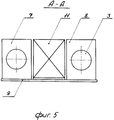
По отношению к прототипу заявляемое изобретение имеет отличительные признаки, заключающиеся в том, что основание стрелы выполнено в виде четного числа параллельных опорных секций, каждая из которых жестко соединена поперечинами, а в целом образуют между собой по всей длине прямоугольный проем, в котором установлен с возможностью перемещения относительно общей оси маневровый гусек, причем маневровый гусек взаимосвязан с порталом стрелы по четырех точечной системе, оси которых взаимно перпендикулярны друг к другу, посредством гидроцилиндра и оголовка стрелы с проушиной, кроме того, маневровый гусек имеет на проушине монтажную подложку. In relation to the prototype, the claimed invention has distinctive features, namely, that the base of the boom is made in the form of an even number of parallel supporting sections, each of which is rigidly connected by cross members, and as a whole form a rectangular opening between them along the entire length, with which movement relative to the common axis of the shunting jib, and the shunting jib is interconnected with the boom portal along four point systems, the axes of which are mutually perpendicular to each other, by means of a hydraulic cylinder The bow and the head of the boom with an eye, in addition, the shunting jib has an mounting substrate on the eye.
Между отличительными признаками и целью изобретения существует причинно-следственная связь, при которой технический результат обусловлен положительным эффектом в виде повышения эффективности путем увеличения грузоподъемности стрелы, расширения технологических возможностей и повышения эксплуатационной надежности. Between the distinguishing features and the purpose of the invention there is a causal relationship in which the technical result is due to a positive effect in the form of increased efficiency by increasing the load capacity of the boom, expanding technological capabilities and increasing operational reliability.
Совокупность заявляемого изобретения из известного уровня техники для специалистов явным образом не следует, в то же время полученный положительный эффект в общей совокупности признаков отличается заявляемое техническое решение от прототипа, что позволяет сделать вывод о его соответствии критерию "Изобретательский уровень". The totality of the claimed invention from the prior art for specialists does not explicitly follow, at the same time, the obtained positive effect in the total set of features differs the claimed technical solution from the prototype, which allows us to conclude that it meets the criterion of "Inventive step".
Совокупность существенных признаков, характеризующих сущность изобретения, могут быть многократно использованы в подъемно-транспортном средстве, что позволяет сделать вывод о соответствии изобретения критерию "Промышленная применимость". The set of essential features characterizing the essence of the invention can be repeatedly used in a truck, which allows us to conclude that the invention meets the criterion of "Industrial applicability".
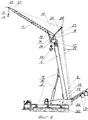
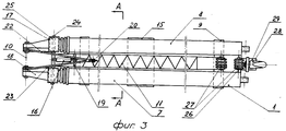
На фиг.1 дан общий вид устройства при подъеме высокотоннажного груза; на фиг. 2 - общий вид устройства при подъеме груза до 50 т; на фиг.3 - вид на стрелу сверху в транспортном положении; на фиг.4 - вид на стрелу сбоку в транспортном положении; на фиг.5 - вид сечения стрелы А-А. Figure 1 is a General view of the device when lifting high-tonnage cargo; in FIG. 2 - general view of the device when lifting cargo up to 50 tons; figure 3 is a view of the arrow from above in the transport position; figure 4 is a side view of the arrow in the transport position; figure 5 is a cross-sectional view of the arrow aa.
Стрела 1 автокрана 2 высокой грузоподъемности включает основание стрелы жесткой, сварной конструкции с встречными телескопическими силовыми гидроцилиндрами 3 привода выдвижных секций 4-6. Кроме того, основание стрелы 1 выполнено еще в виде четного числа параллельных опорных секций 7, 8, каждая из которых жестко соединена поперечинами 9 и в целом образуют между собой по всей длине прямоугольный "![]()
![]()
Автокран 2 оборудован гидроопорами 30, а поворотная платформа 12 включает противовесы 31 с гидроцилиндрами 32 привода из перемещения. Все гидроцилиндры 3, 14, 16, 32 запитаны от общей гидравлической системы автокрана 2. The
Для проведения подъемно-транспортных работ по перемещению груза автокран 2 переводят из транспортного положения в рабочее. Для этого его вначале устанавливают на исходное рабочее место для проведения грузоподъемных операций. Затем шасси автокрана 2 устанавливают на опоры 30 и вводят в работу противовесы 31 под действием силового гидроцилиндра 32. Далее для проведения работ под действием гидроцилиндров 14 поднимают основание телескопической стрелы 1. Под действием силовых телескопических гидроцилиндров 3 выдвигаются секции 4-6 из опорных секций 7, 8 стрелы 1 на величину требуемой технологической грузоподъемной операции. После чего перемещаемый груз зацепляют посредством крюка 33 через трособлочную систему 21 главного подъемна и за счет возможного движения поворотной платформы 12 на поворотном круге 13 автокрана 2 перемещают на заданную технологическую отметку. В таком положении можно производить грузоподъемные операции особотяжелых грузов, например, за 300 т и более. Для проведения работ на этой же базе и технологической рабочей отметке с малотонажным грузом до 50 т можно производить операции грузоподъема маневровым гуськом 11. Для этого сложенный гусек 11 вспомогательного подъема выводится из транспортного положения из прямоугольного "![]()
![]()
После вывода гуська 11 со стойкой 22 в исходное рабочее положение гидроцилиндр 16 отключается, а подъем грузов производится только за счет блока роликов 27 крюка 28 трособлочной системы 21 вспомогательного подъема на оголовке 26 гуська 11. Привод всех гидроцилиндров 3, 14, 16, 32 осуществляется от общей гидравлической системы автокрана 2. После проведения всех подъемно-транспортных работ перевод в транспортное положение гуська +1 стрелы 1 и в целом автокрана 2 производится в обратной последовательности. After the
Использование основания стрелы 1 в виде четного числа параллельных опорных секций 7, 8 позволяет существенно увеличить грузоподъемность стрелы 1 и в целом автокрана 2. Соединение опорных секций 7, 8 основания стрелы 1 поперечинами 9 с образованием по всей длине прямоугольного ![]()
![]()
Применение в целом заявляемого технического решения, например, при строительстве крупных промышленных объектов (АЭС, ТЭЦ и т.д.) позволит более эффективно вести монтаж сооружений благодаря использованию отечественного подъемно-транспортного средства повышенной грузоподъемности, например, автокрана грузоподъемностью свыше 300 т не прибегая к услугам зарубежных фирм. The application of the claimed technical solution as a whole, for example, in the construction of large industrial facilities (nuclear power plants, thermal power plants, etc.) will allow more efficient installation of facilities through the use of a domestic truck with increased carrying capacity, for example, a truck crane with a carrying capacity of over 300 tons without resorting to the services of foreign firms.
Claims (2)
Priority Applications (1)
| Application Number | Priority Date | Filing Date | Title |
|---|---|---|---|
| RU96107357A RU2106295C1 (en) | 1996-04-03 | 1996-04-03 | Boom of high load capacity truck crane |
Applications Claiming Priority (1)
| Application Number | Priority Date | Filing Date | Title |
|---|---|---|---|
| RU96107357A RU2106295C1 (en) | 1996-04-03 | 1996-04-03 | Boom of high load capacity truck crane |
Publications (2)
| Publication Number | Publication Date |
|---|---|
| RU2106295C1 true RU2106295C1 (en) | 1998-03-10 |
| RU96107357A RU96107357A (en) | 1998-05-20 |
Family
ID=20179361
Family Applications (1)
| Application Number | Title | Priority Date | Filing Date |
|---|---|---|---|
| RU96107357A RU2106295C1 (en) | 1996-04-03 | 1996-04-03 | Boom of high load capacity truck crane |
Country Status (1)
| Country | Link |
|---|---|
| RU (1) | RU2106295C1 (en) |
Cited By (8)
| Publication number | Priority date | Publication date | Assignee | Title |
|---|---|---|---|---|
| RU2155680C1 (en) * | 1999-07-09 | 2000-09-10 | Открытое акционерное общество Галичский автокрановый завод | Truck-mounted hydraulic crane plant |
| RU2200123C1 (en) * | 2001-12-24 | 2003-03-10 | Селиванов Николай Павлович | Truck crane plant |
| RU2200124C1 (en) * | 2001-12-24 | 2003-03-10 | Селиванов Николай Павлович | Articulated telescopic boom |
| RU2200125C1 (en) * | 2001-12-24 | 2003-03-10 | Селиванов Николай Павлович | Truck crane |
| WO2011087398A1 (en) * | 2010-01-12 | 2011-07-21 | Корчагина Марина Евгеньевна | Lift crane system |
| RU2434803C1 (en) * | 2010-04-08 | 2011-11-27 | Олег Станиславович Баринов | Device for telescoping truck crane 4-section boom |
| WO2012080455A1 (en) * | 2010-12-17 | 2012-06-21 | Tadano Faun Gmbh | Mobile telescopic crane |
| WO2013141892A1 (en) * | 2012-03-21 | 2013-09-26 | Mark Bobeck | Kingpost crane apparatus & method |
Citations (1)
| Publication number | Priority date | Publication date | Assignee | Title |
|---|---|---|---|---|
| SU523630A3 (en) * | 1971-01-26 | 1976-07-30 | Лео Готтвальд Кг, (Фирма) | Telescopic boom |
-
1996
- 1996-04-03 RU RU96107357A patent/RU2106295C1/en active
Patent Citations (1)
| Publication number | Priority date | Publication date | Assignee | Title |
|---|---|---|---|---|
| SU523630A3 (en) * | 1971-01-26 | 1976-07-30 | Лео Готтвальд Кг, (Фирма) | Telescopic boom |
Cited By (20)
| Publication number | Priority date | Publication date | Assignee | Title |
|---|---|---|---|---|
| RU2155680C1 (en) * | 1999-07-09 | 2000-09-10 | Открытое акционерное общество Галичский автокрановый завод | Truck-mounted hydraulic crane plant |
| RU2200123C1 (en) * | 2001-12-24 | 2003-03-10 | Селиванов Николай Павлович | Truck crane plant |
| RU2200124C1 (en) * | 2001-12-24 | 2003-03-10 | Селиванов Николай Павлович | Articulated telescopic boom |
| RU2200125C1 (en) * | 2001-12-24 | 2003-03-10 | Селиванов Николай Павлович | Truck crane |
| EP2524893A4 (en) * | 2010-01-12 | 2013-07-10 | Pavel Vladimirovich Korchagin | Lift crane system |
| WO2011087398A1 (en) * | 2010-01-12 | 2011-07-21 | Корчагина Марина Евгеньевна | Lift crane system |
| RU2434803C1 (en) * | 2010-04-08 | 2011-11-27 | Олег Станиславович Баринов | Device for telescoping truck crane 4-section boom |
| CN103269970A (en) * | 2010-12-17 | 2013-08-28 | 多田野发运有限公司 | Mobile telescopic crane |
| WO2012080452A1 (en) * | 2010-12-17 | 2012-06-21 | Tadano Faun Gmbh | Mobile telescopic crane |
| CN103261083A (en) * | 2010-12-17 | 2013-08-21 | 多田野发运有限公司 | Mobile telescopic crane |
| WO2012080455A1 (en) * | 2010-12-17 | 2012-06-21 | Tadano Faun Gmbh | Mobile telescopic crane |
| RU2547492C2 (en) * | 2010-12-17 | 2015-04-10 | Тадано Фаун Гмбх | Movable telescopic lifting crane |
| RU2548652C2 (en) * | 2010-12-17 | 2015-04-20 | Тадано Фаун Гмбх | Movable telescopic hoisting crane |
| CN103261083B (en) * | 2010-12-17 | 2015-04-29 | 多田野发运有限公司 | Mobile telescopic crane |
| CN103269970B (en) * | 2010-12-17 | 2015-04-29 | 多田野发运有限公司 | Mobile telescopic crane |
| US9376292B2 (en) | 2010-12-17 | 2016-06-28 | Tadano Faun Gmbh | Mobile telescopic crane |
| US9637358B2 (en) | 2010-12-17 | 2017-05-02 | Tadano Faun Gmbh | Mobile telescopic crane |
| US8863966B2 (en) | 2011-03-21 | 2014-10-21 | Dynaking Crane, Llc | Kingpost crane apparatus and method |
| US9738496B2 (en) | 2011-03-21 | 2017-08-22 | Dynaking Crane, Llc | Kingpost crane apparatus and method |
| WO2013141892A1 (en) * | 2012-03-21 | 2013-09-26 | Mark Bobeck | Kingpost crane apparatus & method |
Similar Documents
| Publication | Publication Date | Title |
|---|---|---|
| US5642821A (en) | Mobile crane with improved boom construction | |
| CA1240290A (en) | Super size crane | |
| US10781083B2 (en) | Mobile crane and method for angling a main boom extension in relation to a main boom of a mobile crane | |
| US4660731A (en) | Telescopic crane for heavy loads | |
| US3830376A (en) | Telescopic jib and bearing means therefor | |
| US10640339B2 (en) | Mobile crane and method for angling a main jib extension relative to a main jib of a mobile crane | |
| US4446976A (en) | Reversible outrigger crane support | |
| US8167153B1 (en) | Hoist platform and scaffolding attachment means | |
| EP1084984B1 (en) | Mobile crane, particularly port mobile crane, for normal and heavy loads | |
| RU2106295C1 (en) | Boom of high load capacity truck crane | |
| US7686174B2 (en) | Vehicle crane with a telescopic boom, as well as process for assembling and disassembling the anchor supports of the telescopic boom | |
| US3664516A (en) | Folding crane boom | |
| US6032809A (en) | Apparatus for reducing the axle load of a multiaxle movable telescopic crane | |
| CN111717102A (en) | A remote-controlled launch pad transport vehicle and method for loading and unloading launch pads | |
| EP1673304B1 (en) | A mobile crane | |
| CN214356022U (en) | A two-stage folding cross-board device | |
| JPH02282195A (en) | lifter device | |
| RU2216462C2 (en) | Loader | |
| US7370767B2 (en) | Mobile crane | |
| JPS59207393A (en) | Rapid prefabricated type boom for travelling type crane | |
| WO2021140011A1 (en) | A mobile heavy lift crane system | |
| RU228940U1 (en) | CRANE INSTALLATION ON A TWO-LINK TRACKED ALL-TERRAIN SNOW AND SWAMP VEHICLE | |
| RU2063375C1 (en) | Load-lifting crane | |
| JP2794385B2 (en) | Structure jack-up method and jack-up device | |
| CN210620066U (en) | Crane equipment |