EP1292416B1 - Tool coupling - Google Patents
Tool coupling Download PDFInfo
- Publication number
- EP1292416B1 EP1292416B1 EP01934735A EP01934735A EP1292416B1 EP 1292416 B1 EP1292416 B1 EP 1292416B1 EP 01934735 A EP01934735 A EP 01934735A EP 01934735 A EP01934735 A EP 01934735A EP 1292416 B1 EP1292416 B1 EP 1292416B1
- Authority
- EP
- European Patent Office
- Prior art keywords
- teeth
- male part
- female seat
- tool
- recesses
- Prior art date
- Legal status (The legal status is an assumption and is not a legal conclusion. Google has not performed a legal analysis and makes no representation as to the accuracy of the status listed.)
- Expired - Lifetime
Links
- 230000008878 coupling Effects 0.000 title claims abstract description 47
- 238000010168 coupling process Methods 0.000 title claims abstract description 47
- 238000005859 coupling reaction Methods 0.000 title claims abstract description 47
- 238000003754 machining Methods 0.000 claims description 4
- 230000000452 restraining effect Effects 0.000 abstract 2
- 239000002184 metal Substances 0.000 abstract 1
- 230000005540 biological transmission Effects 0.000 description 2
- 241000270295 Serpentes Species 0.000 description 1
- 238000005452 bending Methods 0.000 description 1
- 230000001419 dependent effect Effects 0.000 description 1
- 238000006073 displacement reaction Methods 0.000 description 1
- 238000003801 milling Methods 0.000 description 1
- 238000012986 modification Methods 0.000 description 1
- 230000004048 modification Effects 0.000 description 1
Images


Classifications
-
- B—PERFORMING OPERATIONS; TRANSPORTING
- B23—MACHINE TOOLS; METAL-WORKING NOT OTHERWISE PROVIDED FOR
- B23B—TURNING; BORING
- B23B29/00—Holders for non-rotary cutting tools; Boring bars or boring heads; Accessories for tool holders
- B23B29/04—Tool holders for a single cutting tool
- B23B29/08—Tool holders equipped with grooves arranged crosswise to the longitudinal direction for setting the cutting tool
-
- B—PERFORMING OPERATIONS; TRANSPORTING
- B23—MACHINE TOOLS; METAL-WORKING NOT OTHERWISE PROVIDED FOR
- B23B—TURNING; BORING
- B23B31/00—Chucks; Expansion mandrels; Adaptations thereof for remote control
- B23B31/008—Chucks; Expansion mandrels; Adaptations thereof for remote control with arrangements for transmitting torque
-
- B—PERFORMING OPERATIONS; TRANSPORTING
- B23—MACHINE TOOLS; METAL-WORKING NOT OTHERWISE PROVIDED FOR
- B23B—TURNING; BORING
- B23B27/00—Tools for turning or boring machines; Tools of a similar kind in general; Accessories therefor
- B23B27/04—Cutting-off tools
-
- B—PERFORMING OPERATIONS; TRANSPORTING
- B23—MACHINE TOOLS; METAL-WORKING NOT OTHERWISE PROVIDED FOR
- B23B—TURNING; BORING
- B23B31/00—Chucks; Expansion mandrels; Adaptations thereof for remote control
- B23B31/02—Chucks
- B23B31/10—Chucks characterised by the retaining or gripping devices or their immediate operating means
- B23B31/11—Retention by threaded connection
-
- B—PERFORMING OPERATIONS; TRANSPORTING
- B23—MACHINE TOOLS; METAL-WORKING NOT OTHERWISE PROVIDED FOR
- B23B—TURNING; BORING
- B23B2205/00—Fixation of cutting inserts in holders
- B23B2205/02—Fixation using an elastically deformable clamping member
-
- B—PERFORMING OPERATIONS; TRANSPORTING
- B23—MACHINE TOOLS; METAL-WORKING NOT OTHERWISE PROVIDED FOR
- B23B—TURNING; BORING
- B23B2210/00—Details of turning tools
- B23B2210/08—Tools comprising intermediary toolholders
-
- F—MECHANICAL ENGINEERING; LIGHTING; HEATING; WEAPONS; BLASTING
- F16—ENGINEERING ELEMENTS AND UNITS; GENERAL MEASURES FOR PRODUCING AND MAINTAINING EFFECTIVE FUNCTIONING OF MACHINES OR INSTALLATIONS; THERMAL INSULATION IN GENERAL
- F16B—DEVICES FOR FASTENING OR SECURING CONSTRUCTIONAL ELEMENTS OR MACHINE PARTS TOGETHER, e.g. NAILS, BOLTS, CIRCLIPS, CLAMPS, CLIPS OR WEDGES; JOINTS OR JOINTING
- F16B2200/00—Constructional details of connections not covered for in other groups of this subclass
- F16B2200/67—Rigid angle couplings
-
- Y—GENERAL TAGGING OF NEW TECHNOLOGICAL DEVELOPMENTS; GENERAL TAGGING OF CROSS-SECTIONAL TECHNOLOGIES SPANNING OVER SEVERAL SECTIONS OF THE IPC; TECHNICAL SUBJECTS COVERED BY FORMER USPC CROSS-REFERENCE ART COLLECTIONS [XRACs] AND DIGESTS
- Y10—TECHNICAL SUBJECTS COVERED BY FORMER USPC
- Y10T—TECHNICAL SUBJECTS COVERED BY FORMER US CLASSIFICATION
- Y10T407/00—Cutters, for shaping
- Y10T407/22—Cutters, for shaping including holder having seat for inserted tool
- Y10T407/227—Cutters, for shaping including holder having seat for inserted tool with separate means to fasten tool seat to holder
-
- Y—GENERAL TAGGING OF NEW TECHNOLOGICAL DEVELOPMENTS; GENERAL TAGGING OF CROSS-SECTIONAL TECHNOLOGIES SPANNING OVER SEVERAL SECTIONS OF THE IPC; TECHNICAL SUBJECTS COVERED BY FORMER USPC CROSS-REFERENCE ART COLLECTIONS [XRACs] AND DIGESTS
- Y10—TECHNICAL SUBJECTS COVERED BY FORMER USPC
- Y10T—TECHNICAL SUBJECTS COVERED BY FORMER US CLASSIFICATION
- Y10T407/00—Cutters, for shaping
- Y10T407/22—Cutters, for shaping including holder having seat for inserted tool
- Y10T407/2272—Cutters, for shaping including holder having seat for inserted tool with separate means to fasten tool to holder
- Y10T407/2274—Apertured tool
-
- Y—GENERAL TAGGING OF NEW TECHNOLOGICAL DEVELOPMENTS; GENERAL TAGGING OF CROSS-SECTIONAL TECHNOLOGIES SPANNING OVER SEVERAL SECTIONS OF THE IPC; TECHNICAL SUBJECTS COVERED BY FORMER USPC CROSS-REFERENCE ART COLLECTIONS [XRACs] AND DIGESTS
- Y10—TECHNICAL SUBJECTS COVERED BY FORMER USPC
- Y10T—TECHNICAL SUBJECTS COVERED BY FORMER US CLASSIFICATION
- Y10T407/00—Cutters, for shaping
- Y10T407/25—Cutters, for shaping including cut off tool
-
- Y—GENERAL TAGGING OF NEW TECHNOLOGICAL DEVELOPMENTS; GENERAL TAGGING OF CROSS-SECTIONAL TECHNOLOGIES SPANNING OVER SEVERAL SECTIONS OF THE IPC; TECHNICAL SUBJECTS COVERED BY FORMER USPC CROSS-REFERENCE ART COLLECTIONS [XRACs] AND DIGESTS
- Y10—TECHNICAL SUBJECTS COVERED BY FORMER USPC
- Y10T—TECHNICAL SUBJECTS COVERED BY FORMER US CLASSIFICATION
- Y10T82/00—Turning
- Y10T82/25—Lathe
- Y10T82/2585—Tool rest
- Y10T82/2591—Tool post
Definitions
- the present invention relates to a tool coupling, preferably for turning tools, for coupling together a fastening part and a tool body which is intended to carry or by itself constitute a cutting insert for chip removing machining, the tool coupling comprising a male part, having a first centre axis, and a female seat, having a second centre axis, the female seat being intended to receive the male part.
- a replaceable cutting body, a so-called loose top, that is attached to a shaft is previously known from DE-OS 34 02 547 .
- the tool in question is especially suited for internal turning.
- the connection between the cutting body and the shaft is formed in such a way that three radial grooves are recessed in the end of the shaft turned towards the cutting body, while three radial ridges are arranged on the cutting body.
- an axial screw extends through the cutting body and into the shaft, the ridges being received in the grooves. Thereby, a torque may be transferred from the shaft to the cutting body.
- a primary aim of the present invention is to provide a tool coupling being capable of transmitting large torques.
- Another aim of the present invention is that also at a moderate axial prestress, there should be an exceptionally small risk of the transmission of torque failing to work.
- Yet another aim of the present invention is to provide a self-centering tool coupling.
- An additional aim is to provide a tool coupling, being free of play.
- the invention also relates to two different tool bodies to be used in the coupling. These tool bodies are defined in claims 6 and 7 respectively.
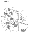
- the tool illustrated in Figs 1-3 is intended to be used for, for instance, parting and grooving, and comprises an adaptor or fastening part in the form of a tool holder 1, which is provided with a male part 3 included in the tool coupling according to the invention. This male part 3 will be described in more detail below.
- the tool holder 1 also comprises an insert seat 2 for receipt of a cutting insert (not shown) for chip removing machining.
- the male part 3 (see Fig 1), comprises a number of first teeth 5, which are spaced-apart from each other, and are tangent to an imaginary circle having its centre along a first centre axis 7, and are directed radially away from said first centre axis 7.
- the first teeth 5 are interspaced by a number of first recesses 9, which in turn are tangent to an imaginary circle also having its centre along the first centre axis 7, and are directed away from said first centre axis 7.
- the male part 3 including the teeth thereof has a slightly conical shape, if so, the cone angle ⁇ , see Fig 4, being in the range of 1°-30°, preferably 2°-14°.
- a first internally threaded cylindrical hole 6 is recessed having the centre thereof along the first centre axis 7.
- a fastening part or adaptor 10 is shown, one end of which is intended to be coupled to a machine tool.
- adaptor 10 has a female seat 11 included in the tool coupling according to the invention.
- This female seat is formed to fit the male part 3, i.e. the male part 3 should be received in the female seat 11.
- the female seat 11 comprises a number of second teeth 12, which are spaced-apart from each other, and which are tangent to an imaginary circle having its centre along a second centre axis 13, and are directed radially inward from the surrounding land.
- the second teeth 12 are spaced-apart by a number of second recesses 14, which are tangent to an imaginary circle also having its centre along the second centre axis 13.
- the female seat 11, including the teeth thereof, has a slightly conical shape, with a conicity equalling the conicity of the male part 3.
- a second internally threaded cylindrical hole 15 is recessed having the centre thereof along the second centre axis 13.
- the teeth 5, 12 have a convex free end and the recesses 9, 14 have a concave bottom.
- shape of the teeth 5, 12 and the recesses 9, 14 may vary widely within the scope of the invention, as illustrated in Figs 10-14.
- the tool coupling comprises a male part 3 and a female seat 11, the same being formed to mate and to force-wise co-operate with each other as for the transmission of torque between the tool body 1 and the adaptor 10, the first and second the centre axes 7, 13 coinciding with each other, in the assembled state.
- the tool body 1 and the adaptor 10 are shown in the position to be coupled together, i.e. the male part 3 should be received in the female seat 11.
- a screw 17 is arranged, said screw 17 being provided with external threads 18, 19 at the two ends thereof.
- Fig 4 the section A-A of Fig 9 through the contact area for the mutual abutment or contact between a tooth and a recess is shown.
- the direct abutment takes place between the conical surfaces of the interengaging teeth while there is a limited play between those surfaces of the coupling which are situated farthest away from the centre axis.
- a turning tool 21' which has a triangular cutting insert 22' received in an insert seat in a holder 23' included in the turning tool 21'.
- the cutting insert 22' is in the usual way secured in the insert seat by means of a securing screw 24' extending through a central hole 25' in the cutting insert.
- the centre of the hole 25' is situated along a centre axis 7', which also is the centre axis of the screw 24'.
- the cutting insert 22' is provided with a male part 3' which is included in the tool coupling according to the invention.
- Said male part 3' has principally the same design as the male part 3 of the embodiment according to Figs 1-4, i.e.
- the male part 3' comprises a number of first teeth, which are spaced-apart from each other, and which are tangent to an imaginary circle having its centre along the centre axis 7', and extend in the direction radially from said centre axis 7'.
- the first teeth are spaced-apart by a number of first recesses, which are tangent to an imaginary circle also having its centre along the centre axis 7'.
- the male part 3' has a slightly conical shape.
- the insert seat of the holder 23' is in the form of a female seat 11', which has principally the same design as the female seat 11.
- the male part 3' of said cutting insert is received in the female seat of the holder 23'.
- the securing screw 24' By tightening the securing screw 24', the male part 3' and the female seat 11' will come into abutment against each other, preferably in the way illustrated in Fig 4.
- the securing screw 24' is loosened and the cutting insert 22' is turned to a position where the male part 3' and the female seat 11' again fit into each other. Then the securing screw 24' is retightened.
- a circular cutting insert 22" is shown, the bottom side of which is provided with a female seat 11" of the same design as the female seat 11, i.e. the female seat 11" is provided with a number of second teeth 12", which are spaced-apart from each other, and are tangent to an imaginary circle having its centre on a second centre axis 13".
- the teeth are directed radially towards said second centre axis 13".
- the second teeth 12" are spaced-apart by a number of second recesses 14", which are tangent to an imaginary circle having its centre on the second centre axis 13", and extend radially towards centre axis 13".
- the female seat 11 has a slightly conical shape, with a conicity which preferably equals the conicity of a cooperating male part.
- a second internally threaded cylindrical hole 15" is recessed having a centre coinciding with the second centre axis 13".
- the cutting insert 22" is intended to be secured to a holder (not shown), including a male part having a shape fitting the female seat.
- the circular cutting insert 22" is secured to the holder in a corresponding way as the triangular cutting insert 22', i.e. by means of a securing screw (not shown).
- Figs 9-14 a number of embodiments of co-operating teeth and recesses, respectively, are shown, which are included in tool couplings according to the invention, i.e. the illustrated tooth is normally included in a male part while the illustrated recess normally is included in a female seat.
- a detail of a tooth 5 of the male part 3 and a tooth 12 of the female seat 11 are shown.
- the female seat 11 applies a rotation to the male part 3 by the fact that the tooth 12 of the female seat 11 is in contact with the tooth 5 of the male part 3. In doing so, one or more contact areas P arise between these cooperating teeth 5 and 12.
- a driving angle ⁇ it should in this connection be understood the angle ⁇ which is formed between a line L which is perpendicular to the plane of force F in the contact area P between the teeth 5, 12 as well as a symmetry line CL for the tooth 5 of the male part 3.
- the driving angles ⁇ are drawn in for different embodiments of teeth and co-operating recesses in a coupling according to the invention.
- a tooth and a co-operating recess do not need to have a shape corresponding with each other.
- the essential thing is that a contact area P is formed between the teeth 5 and 12, at which there in principle does not have to be any mutual abutment between the teeth and the appurtenant recess besides said contact area P.
- the driving angle ⁇ as it is defined in Fig 9, should be in the interval -5° - +45°, preferably -2° - +25°.
- the number of teeth of the male part 3; 3' and the female part 11; 11' may vary between 3 and 12, preferably between 6 and 8.
- the male parts and female seats are formed with identical teeth around the entire circumference thereof.
- the teeth of the male part and the female seat have a different design along the circumference of the male part and the female seat, respectively. Thereby, a guiding of the mutual indexing of the male part and the female seat can take place, i.e. they only fit together in a limited number of positions.
- all teeth have an equally large radial extension from the centre axis 7, 13; 7'; 13".
- some tooth or teeth have an extension from the centre axis 7, 13; 7'; 13" deviating from the extension of the other teeth. This may, for instance, be the case if the tool coupling is desired to be indexed in a special position.
- the male part 3; 3' is alternatively situated on the part of the tool which carries the cutting members/constitutes the cutting member for the chip removing machining or on the proper tool body/holder.
- the same is valid for the female seat 11; 11".
- This variation of the location of the male part 3; 3' and the female seat 11; 11" is general.
- tool coupling according to the present invention has been described in connection with a turning tool for parting and grooving. However, this only constitutes examples of tools where the tool coupling according to the present invention may be applied. However, tool couplings according to the invention may also be used together with rotary tools, for instance milling cutters or drills.
Applications Claiming Priority (3)
| Application Number | Priority Date | Filing Date | Title |
|---|---|---|---|
| SE0001827A SE516501C2 (sv) | 2000-05-18 | 2000-05-18 | Verktygskoppling |
| SE0001827 | 2000-05-18 | ||
| PCT/SE2001/001062 WO2001087523A1 (en) | 2000-05-18 | 2001-05-15 | Tool coupling |
Publications (2)
| Publication Number | Publication Date |
|---|---|
| EP1292416A1 EP1292416A1 (en) | 2003-03-19 |
| EP1292416B1 true EP1292416B1 (en) | 2007-11-14 |
Family
ID=20279712
Family Applications (1)
| Application Number | Title | Priority Date | Filing Date |
|---|---|---|---|
| EP01934735A Expired - Lifetime EP1292416B1 (en) | 2000-05-18 | 2001-05-15 | Tool coupling |
Country Status (9)
| Country | Link |
|---|---|
| US (1) | US6601486B2 (ja) |
| EP (1) | EP1292416B1 (ja) |
| JP (1) | JP4819284B2 (ja) |
| KR (1) | KR100770677B1 (ja) |
| CN (1) | CN1191905C (ja) |
| AT (1) | ATE378130T1 (ja) |
| DE (1) | DE60131394T2 (ja) |
| SE (1) | SE516501C2 (ja) |
| WO (1) | WO2001087523A1 (ja) |
Families Citing this family (23)
| Publication number | Priority date | Publication date | Assignee | Title |
|---|---|---|---|---|
| SE516003C2 (sv) * | 2000-03-02 | 2001-11-05 | Sandvik Ab | Verktyg med snedställda monteringsytor mellan hållar- och verktygsdel |
| SE521579C2 (sv) † | 2002-03-21 | 2003-11-11 | Sandvik Ab | Verktyg samt skär för spånavskiljande bearbetning |
| DE10222446A1 (de) | 2002-05-22 | 2003-12-04 | Horn P Hartmetall Werkzeugfab | Bearbeitungswerkzeug, insbesondere Fräswerkzeug |
| SE526539C2 (sv) * | 2002-05-28 | 2005-10-04 | Sandvik Intellectual Property | Verktyg för spånavskiljande bearbetning där skärläget uppvisar flexibla partier. |
| US7619762B2 (en) * | 2003-04-28 | 2009-11-17 | Lexmark International, Inc. | Customizable multi-function printing device |
| SE526767C2 (sv) * | 2003-10-16 | 2005-11-01 | Sandvik Intellectual Property | Skärverktyg med tillsatskropp med serrationsyta samt förfarande för tillverkning av skärverktyg |
| SE526586C2 (sv) * | 2003-11-25 | 2005-10-11 | Sandvik Intellectual Property | Verktyg för spånavskiljande bearbetning innefattande en han/hon-koppling mellan skärdel och hållardel |
| US20050271483A1 (en) * | 2004-06-02 | 2005-12-08 | Sandvik Ab | Indexable cutting inserts and methods for producing the same |
| JP4407503B2 (ja) † | 2004-12-16 | 2010-02-03 | 三菱マテリアル株式会社 | 切削インサートのクランプ機構 |
| ES2307352B1 (es) * | 2005-04-12 | 2009-09-18 | Bti, I+D, S.L. | Implante dental y piezas destinadas a ser conectadas a un implante dental, y la conexion interna entre el implante dental y cada pieza. |
| IL185047A (en) * | 2007-08-05 | 2011-09-27 | Iscar Ltd | Cutting Tools |
| SE533850C2 (sv) * | 2009-06-23 | 2011-02-08 | Sandvik Intellectual Property | Borrverktyg av löstoppstyp |
| SE534648C2 (sv) * | 2010-03-26 | 2011-11-08 | Sandvik Intellectual Property | Roterbart verktyg för spånavskiljande bearbetning samt löstopp och grundkropp härför |
| EP2764939B2 (en) | 2011-10-07 | 2022-12-07 | Tungaloy Corporation | Cutting tool with replaceable blade edge |
| EP2581157B1 (en) * | 2011-10-11 | 2020-04-01 | VARGUS Ltd. | Cutting tool for grooving and parting operations |
| US9120154B2 (en) * | 2013-02-14 | 2015-09-01 | Iscar, Ltd. | Single-sided square-shaped indexable cutting insert and cutting tool |
| US9120156B2 (en) * | 2013-03-26 | 2015-09-01 | Iscar, Ltd. | Rhombus-shaped indexable cutting insert and cutting tool |
| USD741616S1 (en) | 2014-04-02 | 2015-10-27 | Gigtrigger AS | Bench |
| EP3000549B1 (en) * | 2014-09-24 | 2022-11-09 | Sandvik Intellectual Property AB | A cutting tool and a cutting insert for a chip-removing tool |
| WO2016084891A1 (ja) * | 2014-11-27 | 2016-06-02 | 株式会社タンガロイ | 切削インサート及び刃先交換式回転切削工具 |
| US11872638B2 (en) | 2020-07-20 | 2024-01-16 | Iscar, Ltd. | Method of clamping a Y-axis feed direction parting blade or cutting insert and a holder and tool assembly for same |
| JP7012948B1 (ja) * | 2021-03-10 | 2022-01-31 | 株式会社タンガロイ | 刃先交換式切削工具の工具本体 |
| CN114406304A (zh) * | 2022-01-18 | 2022-04-29 | 厦门金鹭特种合金有限公司 | 一种用于切槽、车削及仿形加工的切削刀具 |
Family Cites Families (16)
| Publication number | Priority date | Publication date | Assignee | Title |
|---|---|---|---|---|
| DE3363749D1 (en) * | 1982-07-30 | 1986-07-03 | Gerhard Rall | Cutting tool |
| DE3320693A1 (de) * | 1983-06-08 | 1984-12-13 | Traub Gmbh, 7313 Reichenbach | Werkzeughalter fuer werkzeugmaschinen |
| DE3427125C2 (de) * | 1983-07-23 | 1997-01-30 | Kastner Hermann | Teilbares Werkzeug für die spanabhebende Bearbeitung |
| DE3402547A1 (de) | 1984-01-26 | 1985-08-08 | Hartmetall-Werkzeugfabrik Paul Horn GmbH, 7400 Tübingen | Wechselschneidkoerper, insbesondere fuer ein inneneinstich- und zirkular-werkzeug |
| DE3435119C2 (de) * | 1984-09-25 | 1986-08-07 | Gildemeister-De Vlieg System-Werkzeuge Gmbh, 4800 Bielefeld | Werkzeug- oder Werkstückhalteranordnung für spanende Werkzeugmaschinen |
| JPS6426102U (ja) * | 1987-08-04 | 1989-02-14 | ||
| JPS6426102A (en) * | 1988-07-08 | 1989-01-27 | Toshiba Corp | Shape measuring instrument |
| US5150636A (en) | 1991-06-28 | 1992-09-29 | Loudon Enterprises, Inc. | Rock drill bit and method of making same |
| DE4415033C1 (de) * | 1994-04-29 | 1995-08-10 | Loehr & Bromkamp Gmbh | Verbindung zur harmonischen Übertragung von Drehmoment |
| DE19513905C1 (de) * | 1995-04-12 | 1996-06-20 | Gkn Automotive Ag | Drehfeste Verbindung |
| SE510852C3 (sv) * | 1996-07-10 | 1999-07-19 | Sandvik Ab | Vaendskaer |
| SE512318C2 (sv) * | 1997-08-29 | 2000-02-28 | Sandvik Ab | Verktygskoppling |
| JP3777043B2 (ja) * | 1998-02-27 | 2006-05-24 | 京セラ株式会社 | 丸駒型スローアウェイチップを用いた切削工具 |
| US6238133B1 (en) * | 1998-10-20 | 2001-05-29 | Kennametal Pc Inc. | Anti-rotation mounting mechanism for round cutting insert |
| US6183230B1 (en) * | 1999-03-19 | 2001-02-06 | General Motors Corporation | Isolated engine oil pump drive |
| SE516524C2 (sv) * | 2000-05-18 | 2002-01-22 | Sandvik Ab | Verktygskoppling |
-
2000
- 2000-05-18 SE SE0001827A patent/SE516501C2/sv not_active IP Right Cessation
-
2001
- 2001-05-15 EP EP01934735A patent/EP1292416B1/en not_active Expired - Lifetime
- 2001-05-15 WO PCT/SE2001/001062 patent/WO2001087523A1/en active IP Right Grant
- 2001-05-15 DE DE60131394T patent/DE60131394T2/de not_active Expired - Lifetime
- 2001-05-15 AT AT01934735T patent/ATE378130T1/de not_active IP Right Cessation
- 2001-05-15 JP JP2001583967A patent/JP4819284B2/ja not_active Expired - Lifetime
- 2001-05-15 KR KR1020027015436A patent/KR100770677B1/ko active IP Right Grant
- 2001-05-15 CN CNB018094309A patent/CN1191905C/zh not_active Expired - Lifetime
- 2001-05-18 US US09/859,379 patent/US6601486B2/en not_active Expired - Lifetime
Also Published As
| Publication number | Publication date |
|---|---|
| CN1429141A (zh) | 2003-07-09 |
| SE516501C2 (sv) | 2002-01-22 |
| CN1191905C (zh) | 2005-03-09 |
| ATE378130T1 (de) | 2007-11-15 |
| JP2003533357A (ja) | 2003-11-11 |
| EP1292416A1 (en) | 2003-03-19 |
| SE0001827L (sv) | 2001-11-19 |
| US6601486B2 (en) | 2003-08-05 |
| JP4819284B2 (ja) | 2011-11-24 |
| DE60131394D1 (de) | 2007-12-27 |
| KR20030007629A (ko) | 2003-01-23 |
| KR100770677B1 (ko) | 2007-10-29 |
| WO2001087523A1 (en) | 2001-11-22 |
| SE0001827D0 (sv) | 2000-05-18 |
| US20020002886A1 (en) | 2002-01-10 |
| DE60131394T2 (de) | 2008-09-04 |
Similar Documents
| Publication | Publication Date | Title |
|---|---|---|
| EP1292416B1 (en) | Tool coupling | |
| EP1289703B1 (en) | Tool coupling | |
| EP1469965B1 (en) | Tool coupling for rotating tool | |
| EP1366840B1 (en) | Tool for chip-removing machining | |
| EP1847345B1 (en) | A tool for chip removing metal machining and part therefor | |
| US7131802B2 (en) | Male/female tool coupling for rotary tools | |
| KR100852993B1 (ko) | 칩형성기계가공용 장치 | |
| US7520704B2 (en) | Tool Assembly | |
| US7189039B2 (en) | Tool coupling for rotating tools | |
| JP2003291044A (ja) | 回転工具及びその刃部品 | |
| EP0742065B1 (en) | A cutting tool assembly | |
| EP1239984A2 (en) | Toolholder and insert arrangement with a shrink fit coupling | |
| CN106994527B (zh) | 两个连接部件之间的工具连接及用于工具连接的连接部件 | |
| US6979157B2 (en) | Heavy-duty coupling for tool holder arms of modular design | |
| KR20030007630A (ko) | 툴 커플링 |
Legal Events
| Date | Code | Title | Description |
|---|---|---|---|
| PUAI | Public reference made under article 153(3) epc to a published international application that has entered the european phase |
Free format text: ORIGINAL CODE: 0009012 |
|
| 17P | Request for examination filed |
Effective date: 20021029 |
|
| AK | Designated contracting states |
Kind code of ref document: A1 Designated state(s): AT BE CH CY DE DK ES FI FR GB GR IE IT LI LU MC NL PT SE TR |
|
| RAP1 | Party data changed (applicant data changed or rights of an application transferred) |
Owner name: SANDVIK INTELLECTUAL PROPERTY HB |
|
| RAP1 | Party data changed (applicant data changed or rights of an application transferred) |
Owner name: SANDVIK INTELLECTUAL PROPERTY AB |
|
| 17Q | First examination report despatched |
Effective date: 20060801 |
|
| 17Q | First examination report despatched |
Effective date: 20060801 |
|
| GRAP | Despatch of communication of intention to grant a patent |
Free format text: ORIGINAL CODE: EPIDOSNIGR1 |
|
| GRAS | Grant fee paid |
Free format text: ORIGINAL CODE: EPIDOSNIGR3 |
|
| GRAA | (expected) grant |
Free format text: ORIGINAL CODE: 0009210 |
|
| AK | Designated contracting states |
Kind code of ref document: B1 Designated state(s): AT BE CH CY DE DK ES FI FR GB GR IE IT LI LU MC NL PT SE TR |
|
| REG | Reference to a national code |
Ref country code: GB Ref legal event code: FG4D |
|
| REG | Reference to a national code |
Ref country code: CH Ref legal event code: EP |
|
| REG | Reference to a national code |
Ref country code: IE Ref legal event code: FG4D |
|
| REF | Corresponds to: |
Ref document number: 60131394 Country of ref document: DE Date of ref document: 20071227 Kind code of ref document: P |
|
| PG25 | Lapsed in a contracting state [announced via postgrant information from national office to epo] |
Ref country code: ES Free format text: LAPSE BECAUSE OF FAILURE TO SUBMIT A TRANSLATION OF THE DESCRIPTION OR TO PAY THE FEE WITHIN THE PRESCRIBED TIME-LIMIT Effective date: 20080225 Ref country code: SE Free format text: LAPSE BECAUSE OF FAILURE TO SUBMIT A TRANSLATION OF THE DESCRIPTION OR TO PAY THE FEE WITHIN THE PRESCRIBED TIME-LIMIT Effective date: 20080214 Ref country code: NL Free format text: LAPSE BECAUSE OF FAILURE TO SUBMIT A TRANSLATION OF THE DESCRIPTION OR TO PAY THE FEE WITHIN THE PRESCRIBED TIME-LIMIT Effective date: 20071114 Ref country code: LI Free format text: LAPSE BECAUSE OF FAILURE TO SUBMIT A TRANSLATION OF THE DESCRIPTION OR TO PAY THE FEE WITHIN THE PRESCRIBED TIME-LIMIT Effective date: 20071114 Ref country code: CH Free format text: LAPSE BECAUSE OF FAILURE TO SUBMIT A TRANSLATION OF THE DESCRIPTION OR TO PAY THE FEE WITHIN THE PRESCRIBED TIME-LIMIT Effective date: 20071114 |
|
| NLV1 | Nl: lapsed or annulled due to failure to fulfill the requirements of art. 29p and 29m of the patents act | ||
| REG | Reference to a national code |
Ref country code: CH Ref legal event code: PL |
|
| PG25 | Lapsed in a contracting state [announced via postgrant information from national office to epo] |
Ref country code: AT Free format text: LAPSE BECAUSE OF FAILURE TO SUBMIT A TRANSLATION OF THE DESCRIPTION OR TO PAY THE FEE WITHIN THE PRESCRIBED TIME-LIMIT Effective date: 20071114 |
|
| ET | Fr: translation filed | ||
| PG25 | Lapsed in a contracting state [announced via postgrant information from national office to epo] |
Ref country code: DK Free format text: LAPSE BECAUSE OF FAILURE TO SUBMIT A TRANSLATION OF THE DESCRIPTION OR TO PAY THE FEE WITHIN THE PRESCRIBED TIME-LIMIT Effective date: 20071114 |
|
| PG25 | Lapsed in a contracting state [announced via postgrant information from national office to epo] |
Ref country code: BE Free format text: LAPSE BECAUSE OF FAILURE TO SUBMIT A TRANSLATION OF THE DESCRIPTION OR TO PAY THE FEE WITHIN THE PRESCRIBED TIME-LIMIT Effective date: 20071114 |
|
| PLBE | No opposition filed within time limit |
Free format text: ORIGINAL CODE: 0009261 |
|
| STAA | Information on the status of an ep patent application or granted ep patent |
Free format text: STATUS: NO OPPOSITION FILED WITHIN TIME LIMIT |
|
| PG25 | Lapsed in a contracting state [announced via postgrant information from national office to epo] |
Ref country code: PT Free format text: LAPSE BECAUSE OF FAILURE TO SUBMIT A TRANSLATION OF THE DESCRIPTION OR TO PAY THE FEE WITHIN THE PRESCRIBED TIME-LIMIT Effective date: 20080414 |
|
| 26N | No opposition filed |
Effective date: 20080815 |
|
| PG25 | Lapsed in a contracting state [announced via postgrant information from national office to epo] |
Ref country code: MC Free format text: LAPSE BECAUSE OF NON-PAYMENT OF DUE FEES Effective date: 20080531 |
|
| PG25 | Lapsed in a contracting state [announced via postgrant information from national office to epo] |
Ref country code: GR Free format text: LAPSE BECAUSE OF FAILURE TO SUBMIT A TRANSLATION OF THE DESCRIPTION OR TO PAY THE FEE WITHIN THE PRESCRIBED TIME-LIMIT Effective date: 20080215 |
|
| PG25 | Lapsed in a contracting state [announced via postgrant information from national office to epo] |
Ref country code: IE Free format text: LAPSE BECAUSE OF NON-PAYMENT OF DUE FEES Effective date: 20080515 |
|
| PG25 | Lapsed in a contracting state [announced via postgrant information from national office to epo] |
Ref country code: CY Free format text: LAPSE BECAUSE OF FAILURE TO SUBMIT A TRANSLATION OF THE DESCRIPTION OR TO PAY THE FEE WITHIN THE PRESCRIBED TIME-LIMIT Effective date: 20071114 |
|
| PG25 | Lapsed in a contracting state [announced via postgrant information from national office to epo] |
Ref country code: FI Free format text: LAPSE BECAUSE OF FAILURE TO SUBMIT A TRANSLATION OF THE DESCRIPTION OR TO PAY THE FEE WITHIN THE PRESCRIBED TIME-LIMIT Effective date: 20071114 |
|
| PG25 | Lapsed in a contracting state [announced via postgrant information from national office to epo] |
Ref country code: LU Free format text: LAPSE BECAUSE OF NON-PAYMENT OF DUE FEES Effective date: 20080515 |
|
| PG25 | Lapsed in a contracting state [announced via postgrant information from national office to epo] |
Ref country code: TR Free format text: LAPSE BECAUSE OF FAILURE TO SUBMIT A TRANSLATION OF THE DESCRIPTION OR TO PAY THE FEE WITHIN THE PRESCRIBED TIME-LIMIT Effective date: 20071114 |
|
| REG | Reference to a national code |
Ref country code: FR Ref legal event code: PLFP Year of fee payment: 16 |
|
| REG | Reference to a national code |
Ref country code: FR Ref legal event code: PLFP Year of fee payment: 17 |
|
| REG | Reference to a national code |
Ref country code: FR Ref legal event code: PLFP Year of fee payment: 18 |
|
| PGFP | Annual fee paid to national office [announced via postgrant information from national office to epo] |
Ref country code: DE Payment date: 20200506 Year of fee payment: 20 Ref country code: FR Payment date: 20200427 Year of fee payment: 20 |
|
| PGFP | Annual fee paid to national office [announced via postgrant information from national office to epo] |
Ref country code: IT Payment date: 20200414 Year of fee payment: 20 Ref country code: GB Payment date: 20200506 Year of fee payment: 20 |
|
| REG | Reference to a national code |
Ref country code: DE Ref legal event code: R071 Ref document number: 60131394 Country of ref document: DE |
|
| REG | Reference to a national code |
Ref country code: GB Ref legal event code: PE20 Expiry date: 20210514 |
|
| PG25 | Lapsed in a contracting state [announced via postgrant information from national office to epo] |
Ref country code: GB Free format text: LAPSE BECAUSE OF EXPIRATION OF PROTECTION Effective date: 20210514 |