EP1291459A1 - Washing machine door for a front-load washing machine - Google Patents
Washing machine door for a front-load washing machine Download PDFInfo
- Publication number
- EP1291459A1 EP1291459A1 EP02019176A EP02019176A EP1291459A1 EP 1291459 A1 EP1291459 A1 EP 1291459A1 EP 02019176 A EP02019176 A EP 02019176A EP 02019176 A EP02019176 A EP 02019176A EP 1291459 A1 EP1291459 A1 EP 1291459A1
- Authority
- EP
- European Patent Office
- Prior art keywords
- frontal
- frame
- washing machine
- door cover
- domes
- Prior art date
- Legal status (The legal status is an assumption and is not a legal conclusion. Google has not performed a legal analysis and makes no representation as to the accuracy of the status listed.)
- Granted
Links
Images

Classifications
-
- D—TEXTILES; PAPER
- D06—TREATMENT OF TEXTILES OR THE LIKE; LAUNDERING; FLEXIBLE MATERIALS NOT OTHERWISE PROVIDED FOR
- D06F—LAUNDERING, DRYING, IRONING, PRESSING OR FOLDING TEXTILE ARTICLES
- D06F39/00—Details of washing machines not specific to a single type of machines covered by groups D06F9/00 - D06F27/00
- D06F39/12—Casings; Tubs
- D06F39/14—Doors or covers; Securing means therefor
Definitions
- the invention concerns a washing machine door for a front-load washing machine that has a frontal frame hinged to the housing of the machine and that surrounds a loading opening, into which a transparent frontal door cover is inserted from the drum side and which is held in by means of a mounted gallows frame.
- washing machine door is known from DE 195 15 040 C2 and is round in shape. With this known washing machine door, connecting the three essential components - frontal frame, frontal door cover and gallows frame -, is associated with substantial assembly effort.
- a door for a drum washing machine is known from DE 36 03 211 A1 that comprises a transparent pan-like glass, the surrounding edge of which is attached in a frame.
- the frame in turn comprises an outer opening ring and an inner fitting part.
- the fitting part is snapped into the opening ring and the fitting part is welded by means of a coin die such that the edge of the face wheel is localized. This adds to the expense of assembling the door considerably, however.
- the DE 83 04 273 likewise exhibits a door for a drum washing machine that provides a transparent face wheel with a surrounding edge.
- the edge is held in two complementary rings as a frame that can be assembled. The rings are snapped together and hold the edge of the face wheel in place with flanges that protrude inwards. Consequently, a defined angle between the frame and the face wheel is not ensured and the grip of the edge of the face wheel between both flanges is not always sufficient.
- the frontal frame has bayonet hooks on the backside facing the frontal door cover that are inserted into receiving slots of the frontal door cover and held therein when the frontal door cover is rotated; in that at least part of the bayonet hooks provide fashioned screw domes onto which receptacle domes of the gallows frame can be form locked; and in that the gallows frame can be engaged in rest slots of the frontal door cover with bent caps.
- both components are connected by a simple insertion action with a small turn into an assembly position, in which the gallows frame is merely inserted and snapped to the frontal door cover.
- Separate connector elements are not required since these are all arranged on the three components, preferably as one piece or molded.
- the connections can be implemented to provide zero-backlash so that when operational the assembled washing machine door does not make any noise. All the connection points between the three components are covered and enable a design freedom, which lend the washing machine a high appliance quality.
- a module created accordingly can be used for different washing machine doors, wherein hinge parts, handles, etc. to be added on influence the aesthetic image as a whole.
- One arrangement of the bayonet connectors provides that the free end pieces of the bayonet hooks are in the same rotational sense in circumferential direction of the frontal frame, and that the widths of the receiving slots are aligned to the widths of the bayonet hooks, in particular their free end pieces, and are larger in their circumferential dimension by one locking path than the length of the free end pieces.
- the frontal frame and the frontal door cover which is transparent, take a defined assembled position for attaching the gallows frame, if the additional provision is given that the rotational twist of the frontal door cover attached to the bayonet hooks is limited by at least one stop on the backside of the frontal frame that is guided in a receptacle of the frontal door cover and catches.
- Attaching the gallows frame is made easier in that the screw domes of the bayonet hooks of the frontal frame provide a truncated cone-shaped outer contour and the receptacle domes of the gallows frame provide a truncated cone-shaped inner receptacle, the diameters and the tapers of which are calibrated to each other, wherein the gallows frame is aligned at the same time to the pre-assembled module of frontal frame and frontal door cover.
- a pre-configured and often adequate localization of the gallows frame is achieved according to one design in that the rest tabs of the gallows frame are die-cut in an L-shape and bent, and that rest links or rest edges on the end of the rest tabs reach behind the catch slot of the frontal door cover. Connection and stability can be substantially improved however, in that the screw domes of the frontal frame are also screwed with the receptacle domes of the gallows frame, without incurring cumbersome, additional part and assembly expenses.
- the coverage of all fastening locations and a pleasing, shapely appearance of the washing machine door module are provided in that the frontal frame is closed on the front side and it covers the gallows frame with the snap connections to the frontal door cover and with the bayonet connections between the frontal frame and the frontal door cover as well as the snap-in connection between the receiving domes of the gallows frame and the screw domes of the frontal frame.
- one design provides that the screw domes of the frontal frame are lead through breakthroughs in the frontal door cover into the receiving domes of the gallows frame.
- Fig. 1 only shows only one section of the circular frontal frame 10, which can also be cropped by a straight line in the upper section.
- Four bayonet hooks are distributed over the contour, for example at a 90° pitch, that have an L-shape design and that stand with their free end pieces 12 at a pre-determined distance at the backside of the frontal frame 10.
- the forms of the frontal frame 10 and the frontal door cover 20 determine this distance.
- the free end pieces 12 of the bayonet hooks 11 are aligned in the same rotational sense in circumferential direction of the frontal frame 10 and are inserted into receiving slots 21 of the frontal door cover 20, as is shown in Fig. 2.
- the widths of the receiving slots 21, which point in the circumferential direction, are adjusted to the widths of the bayonet hooks 11, in particular the free end pieces 12.
- the dimension of the receiving slots 21 in circumferential direction of the frontal door cover 20 is larger than the length of the free end pieces 12, such that by accordingly surrounding the frontal door cover 20 against the frontal frame 10, preliminary localization of both elements is achieved as seen in Fig. 2.
- the frontal door cover 10 props up over rounded contact surfaces on the inside of the frontal frame 10 to prevent the formation of a gap. Rotation is thereby limited by means of a stop 15 on the backside of the front fame 10 that is inserted into a receptacle of the frontal door cover 20 and that catches in this and therefore determines the installation lay-out between the frontal frame 10 and the frontal door cover 20.
- the gallows frame 30 can be inserted onto the pre-assembled module of frontal frame 10 and frontal door cover 20.
- the gallows frame 30 has molded receiving domes 31 molded onto the bayonet hooks 11 in the distribution of screw domes 13 that are calibrated to each other in terms of cross-section and shape such that the gallows frame 30 can be arranged into correct assembly position.
- die-cut and bent rest tabs 32 on gallows frame 30 can snap into snap slots 22 of the frontal door cover 20, as is shown in Fig. 6.
- These snap connections can be supported further by screwing one part of the screw dome 13 of the frontal frame 10 to receiving dome 31 of the gallows frame 30, particularly if these are designed appropriately, as shown in the cross-section of Fig. 5.
- the washing machine door module made in this way with simple components, can be provided by known methods with hinges, handles, etc and used for the installation of different washing machine doors.
- a sight glass that protrudes into the inside of the drum can be additionally added to the washing machine-module consisting of frontal frame 10, frontal door cover 20 and gallows frame 30.
Landscapes
- Engineering & Computer Science (AREA)
- Textile Engineering (AREA)
- Main Body Construction Of Washing Machines And Laundry Dryers (AREA)
Abstract
Description
- The invention concerns a washing machine door for a front-load washing machine that has a frontal frame hinged to the housing of the machine and that surrounds a loading opening, into which a transparent frontal door cover is inserted from the drum side and which is held in by means of a mounted gallows frame.
- Such a washing machine door is known from DE 195 15 040 C2 and is round in shape. With this known washing machine door, connecting the three essential components - frontal frame, frontal door cover and gallows frame -, is associated with substantial assembly effort.
- A door for a drum washing machine is known from DE 36 03 211 A1 that comprises a transparent pan-like glass, the surrounding edge of which is attached in a frame. The frame in turn comprises an outer opening ring and an inner fitting part. The fitting part is snapped into the opening ring and the fitting part is welded by means of a coin die such that the edge of the face wheel is localized. This adds to the expense of assembling the door considerably, however.
- The DE 83 04 273 likewise exhibits a door for a drum washing machine that provides a transparent face wheel with a surrounding edge. The edge is held in two complementary rings as a frame that can be assembled. The rings are snapped together and hold the edge of the face wheel in place with flanges that protrude inwards. Consequently, a defined angle between the frame and the face wheel is not ensured and the grip of the edge of the face wheel between both flanges is not always sufficient.
- It is the task of the invention to provide a washing machine door of the type mentioned at the outset in which the three basic components - frontal frame, frontal door cover and gallows frame -, can be assembled with a simple design quickly and securely into a stable module.
- This task is solved according to the invention in that the frontal frame has bayonet hooks on the backside facing the frontal door cover that are inserted into receiving slots of the frontal door cover and held therein when the frontal door cover is rotated; in that at least part of the bayonet hooks provide fashioned screw domes onto which receptacle domes of the gallows frame can be form locked; and in that the gallows frame can be engaged in rest slots of the frontal door cover with bent caps.
- With the bayonet connections between the frontal frame and the frontal door cover, both components are connected by a simple insertion action with a small turn into an assembly position, in which the gallows frame is merely inserted and snapped to the frontal door cover. Separate connector elements are not required since these are all arranged on the three components, preferably as one piece or molded. The connections can be implemented to provide zero-backlash so that when operational the assembled washing machine door does not make any noise. All the connection points between the three components are covered and enable a design freedom, which lend the washing machine a high appliance quality.
- A module created accordingly can be used for different washing machine doors, wherein hinge parts, handles, etc. to be added on influence the aesthetic image as a whole.
- One arrangement of the bayonet connectors provides that the free end pieces of the bayonet hooks are in the same rotational sense in circumferential direction of the frontal frame, and that the widths of the receiving slots are aligned to the widths of the bayonet hooks, in particular their free end pieces, and are larger in their circumferential dimension by one locking path than the length of the free end pieces. According to the turn, the frontal frame and the frontal door cover, which is transparent, take a defined assembled position for attaching the gallows frame, if the additional provision is given that the rotational twist of the frontal door cover attached to the bayonet hooks is limited by at least one stop on the backside of the frontal frame that is guided in a receptacle of the frontal door cover and catches.
- Attaching the gallows frame is made easier in that the screw domes of the bayonet hooks of the frontal frame provide a truncated cone-shaped outer contour and the receptacle domes of the gallows frame provide a truncated cone-shaped inner receptacle, the diameters and the tapers of which are calibrated to each other, wherein the gallows frame is aligned at the same time to the pre-assembled module of frontal frame and frontal door cover.
- A pre-configured and often adequate localization of the gallows frame is achieved according to one design in that the rest tabs of the gallows frame are die-cut in an L-shape and bent, and that rest links or rest edges on the end of the rest tabs reach behind the catch slot of the frontal door cover. Connection and stability can be substantially improved however, in that the screw domes of the frontal frame are also screwed with the receptacle domes of the gallows frame, without incurring cumbersome, additional part and assembly expenses.
- The coverage of all fastening locations and a pleasing, shapely appearance of the washing machine door module are provided in that the frontal frame is closed on the front side and it covers the gallows frame with the snap connections to the frontal door cover and with the bayonet connections between the frontal frame and the frontal door cover as well as the snap-in connection between the receiving domes of the gallows frame and the screw domes of the frontal frame.
- In order for the frontal door cover to be able to extend out widely into the area between the frontal frame and the gallows frame, one design provides that the screw domes of the frontal frame are lead through breakthroughs in the frontal door cover into the receiving domes of the gallows frame.
- If a subsequent design stipulates that the frontal door cover props over rounded support surfaces of the interior side of the frontal frame, then a gap between the frontal frame and the frontal door cover is avoided.
- The invention is described in more detail by means of example embodiments shown in the drawings:
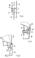
- Fig. 1 shows a partial view of the backside of the frontal frame with bayonet hooks arranged,
- Fig. 2 shows in the local section a snap connection with a bayonet hook of the frontal frame and a receiving slot in the frontal cover,
- Fig. 3 shows a partial view of the backside of the frontal frame with a bayonet hook provided with screw domes and an additional stop,
- Fig. 4 shows a partial section of a rest connection between frontal frame and frontal door cover, wherein the screw dome of the bayonet hook is inserted into a receiving dome of the gallows frame,
- Fig. 5 shows a local section corresponding to Fig. 4, wherein screw dome and receiving dome are set up for an additional connection, however, and
- Fig. 6 shows in the local section a catch between the gallows frame and the frontal door cover.
-
- Fig. 1 only shows only one section of the circular
frontal frame 10, which can also be cropped by a straight line in the upper section. Four bayonet hooks are distributed over the contour, for example at a 90° pitch, that have an L-shape design and that stand with theirfree end pieces 12 at a pre-determined distance at the backside of thefrontal frame 10. The forms of thefrontal frame 10 and thefrontal door cover 20 determine this distance. Thefree end pieces 12 of thebayonet hooks 11 are aligned in the same rotational sense in circumferential direction of thefrontal frame 10 and are inserted into receivingslots 21 of thefrontal door cover 20, as is shown in Fig. 2. The widths of thereceiving slots 21, which point in the circumferential direction, are adjusted to the widths of thebayonet hooks 11, in particular thefree end pieces 12. - The dimension of the
receiving slots 21 in circumferential direction of thefrontal door cover 20 is larger than the length of thefree end pieces 12, such that by accordingly surrounding thefrontal door cover 20 against thefrontal frame 10, preliminary localization of both elements is achieved as seen in Fig. 2. In so doing the frontal door cover 10 props up over rounded contact surfaces on the inside of thefrontal frame 10 to prevent the formation of a gap. Rotation is thereby limited by means of astop 15 on the backside of thefront fame 10 that is inserted into a receptacle of thefrontal door cover 20 and that catches in this and therefore determines the installation lay-out between thefrontal frame 10 and thefrontal door cover 20. - As shown in Fig. 4 and 5, the
gallows frame 30 can be inserted onto the pre-assembled module offrontal frame 10 andfrontal door cover 20. Thegallows frame 30 has molded receivingdomes 31 molded onto thebayonet hooks 11 in the distribution ofscrew domes 13 that are calibrated to each other in terms of cross-section and shape such that thegallows frame 30 can be arranged into correct assembly position. In addition, die-cut andbent rest tabs 32 ongallows frame 30 can snap intosnap slots 22 of thefrontal door cover 20, as is shown in Fig. 6. These snap connections can be supported further by screwing one part of thescrew dome 13 of thefrontal frame 10 to receivingdome 31 of thegallows frame 30, particularly if these are designed appropriately, as shown in the cross-section of Fig. 5. - The washing machine door module, made in this way with simple components, can be provided by known methods with hinges, handles, etc and used for the installation of different washing machine doors. A sight glass that protrudes into the inside of the drum can be additionally added to the washing machine-module consisting of
frontal frame 10,frontal door cover 20 andgallows frame 30.
Claims (9)
- A washing machine door for a front-load washing machine that has a frontal frame hinged to the housing of the machine and that surrounds a loading opening, into which a transparent frontal door cover is inserted from the drum side and is held in by means of a mounted gallows frame,
characterized in that
the frontal frame (10) has bayonet hooks (11) on the backside facing the frontal door cover (20) that are inserted into receiving slots (21) of the frontal door cover (20) and held therein when the frontal door cover is rotated, at least part of the bayonet hooks (11) provide fashioned screw domes (13) onto which receptacle domes (31) of the gallows frame (30) can be form locked and
the gallows frame (30) can be engaged in rest slots (22) of the frontal door cover (20) with bent caps (32). - A washing machine door according to claim 1,
characterized in that
the free end pieces (12) of the bayonet hooks (11) are aligned in the same rotational sense in circumferential direction of the frontal frame (10)
and
that the widths of the receiving slots (21) are aligned to the widths of the bayonet hooks (11), in particular their free end pieces (12), and are larger in their circumferential dimension by one locking path than the length of the free end pieces (12). - A washing machine door according to claims 1 or 2,
characterized in that
the rotational twist of the frontal door cover (20) attached to the bayonet hooks (11) is limited by at least one stop (15) on the backside of the frontal frame (10) that is guided in a receptacle of the frontal door cover (20) and catches. - A washing machine door according to claims 1 through 3,
characterized in that
the screw domes (13) of the bayonet hooks (11) of the frontal frame (10) provide a truncated cone-shaped outer contour and the receptacle domes (31) of the gallows frame (30) provide a truncated cone-shaped inner receptacle, the cross-sections and the tapers of which are calibrated to each other. - A washing machine door according to claims 1 through 4,
characterized in that
the rest tabs (32) of the gallows frame (30) are die-cut in an L-shape and bent, and that rest links or rest edges on the end of the rest tabs (32) reach behind the catch slots (22) of the frontal door cover (20). - A washing machine door according to one of claims 1 through 5,
characterized in that
the frontal frame (10) is closed on the front side and covers the gallows frame (30) with the snap connections to the frontal door cover (20) and with the bayonet connections between the frontal frame (10) and the frontal door cover (20) as well as the snap-in connection between the receiving domes (31) of the gallows frame (30) and the screw domes (13) of the frontal frame (10). - A washing machine door according to one of claims 1 through 6,
characterized in that
the screw domes (13) of the frontal frame (10) are lead through breakthroughs (23) in the frontal door cover (20) into the receiving domes (31) of the gallows frame (30). - A washing machine door according to one of claims 1 through 7,
characterized in that
the screw domes (13) of the frontal frame (10) are also screwed with the receiving domes (31) of the gallows frame (30). - A washing machine door according to one of claims 1 through 8,
characterized in that
the frontal door cover (20) props over rounded support surfaces of the interior side of the frontal frame (10).
Applications Claiming Priority (2)
| Application Number | Priority Date | Filing Date | Title |
|---|---|---|---|
| DE10144767A DE10144767C1 (en) | 2001-09-11 | 2001-09-11 | Door for front-loading washing machine has front frame, transparent front cover and support frame securing latter to front frame |
| DE10144767 | 2001-09-11 |
Publications (2)
| Publication Number | Publication Date |
|---|---|
| EP1291459A1 true EP1291459A1 (en) | 2003-03-12 |
| EP1291459B1 EP1291459B1 (en) | 2006-05-03 |
Family
ID=7698662
Family Applications (1)
| Application Number | Title | Priority Date | Filing Date |
|---|---|---|---|
| EP02019176A Expired - Lifetime EP1291459B1 (en) | 2001-09-11 | 2002-09-02 | Washing machine door for a front-load washing machine |
Country Status (4)
| Country | Link |
|---|---|
| US (1) | US6966204B2 (en) |
| EP (1) | EP1291459B1 (en) |
| DE (2) | DE10144767C1 (en) |
| ES (1) | ES2262736T3 (en) |
Families Citing this family (31)
| Publication number | Priority date | Publication date | Assignee | Title |
|---|---|---|---|---|
| US20040200243A1 (en) * | 2003-04-10 | 2004-10-14 | Maytag Corp. | Washing machine inner lid attachment |
| US7478502B2 (en) * | 2003-08-14 | 2009-01-20 | Gemtron Corporation | Appliance doors |
| AU2004229041B2 (en) | 2003-12-30 | 2011-01-20 | Lg Electronics Inc. | Door of drum-type washing machine, method of manufacturing door with hairline sheet of drum-type washing machine, and method of manufacturing hairline sheet for door |
| US20050262681A1 (en) * | 2004-06-01 | 2005-12-01 | Lg Electronics Inc. | Door of drum washer and assembling method for the same |
| US7305306B2 (en) * | 2005-01-11 | 2007-12-04 | Schlumberger Technology Corporation | System and methods of deriving fluid properties of downhole fluids and uncertainty thereof |
| CA2508860C (en) * | 2005-05-30 | 2007-10-16 | Camco Inc. | Clothes dryer reversible door assembly |
| CA2508607C (en) * | 2005-05-30 | 2007-09-11 | Camco Inc. | Clothes dryer door assembly |
| ES2327455T3 (en) * | 2007-02-27 | 2009-10-29 | Electrolux Home Products Corporation N.V. | FRONT LOAD WASHING MACHINE WITH IMPROVED DOOR. |
| DE102008012192A1 (en) | 2008-03-03 | 2009-09-10 | Miele & Cie. Kg | Front loadable laundry treating machine and door for a front loadable laundry treating machine |
| ES2330293B1 (en) * | 2008-03-12 | 2010-09-16 | Bsh Electrodomesticos España, S.A. | COVER FOR A GLASS OF A DOOR, DOOR WITH SUCH COVER AND WASHING MACHINE AND / OR DRYER WITH SUCH DOOR. |
| KR102127719B1 (en) | 2013-07-08 | 2020-06-29 | 삼성전자주식회사 | Washing machine |
| WO2016119833A1 (en) * | 2015-01-28 | 2016-08-04 | Arcelik Anonim Sirketi | Laundry machine front door opening mechanism involving rigid installation of a handle |
| WO2016155795A1 (en) * | 2015-03-31 | 2016-10-06 | Arcelik Anonim Sirketi | Laundry washing machine with an improved front door mounting mechanism |
| USD827957S1 (en) * | 2015-11-30 | 2018-09-04 | Lg Electronics Inc. | Door for washing machine |
| USD827958S1 (en) * | 2015-11-30 | 2018-09-04 | Lg Electronics Inc. | Door for washing machine |
| USD827234S1 (en) * | 2015-11-30 | 2018-08-28 | Lg Electronics Inc. | Door for washing machine |
| USD822297S1 (en) * | 2016-03-16 | 2018-07-03 | Lg Electronics Inc. | Door for washing machine |
| USD831917S1 (en) * | 2016-03-16 | 2018-10-23 | Lg Electronics Inc. | Door for washing machine |
| USD816927S1 (en) * | 2016-03-16 | 2018-05-01 | Lg Electronics Inc. | Door for washing machine |
| USD831914S1 (en) * | 2016-03-16 | 2018-10-23 | Lg Electronics Inc. | Door for washing machine |
| USD831913S1 (en) * | 2016-03-16 | 2018-10-23 | Lg Electronics Inc. | Door for washing machine |
| USD834272S1 (en) * | 2016-03-16 | 2018-11-20 | Lg Electronics Inc. | Door for washing machine |
| USD831916S1 (en) * | 2016-03-16 | 2018-10-23 | Lg Electronics Inc. | Door for washing machine |
| USD832536S1 (en) * | 2016-03-16 | 2018-10-30 | Lg Electronics Inc. | Door for washing machine |
| USD831912S1 (en) * | 2016-03-16 | 2018-10-23 | Lg Electronics Inc. | Door for washing machine |
| USD832535S1 (en) * | 2016-03-16 | 2018-10-30 | Lg Electronics Inc. | Door for washing machine |
| USD831915S1 (en) * | 2016-03-16 | 2018-10-23 | Lg Electronics Inc. | Door for washing machine |
| PL3323929T3 (en) | 2016-11-21 | 2021-06-28 | Electrolux Appliances Aktiebolag | A door assembly for a laundry treatment machine |
| US11346036B2 (en) | 2019-12-03 | 2022-05-31 | Haler US Appliance Solutions, Inc. | Door assembly for a washing machine appliance |
| US11885061B2 (en) | 2022-06-17 | 2024-01-30 | Haier Us Appliance Solutions, Inc. | Washing machine appliance spacer assembly |
| DE102024109489A1 (en) * | 2024-04-04 | 2025-10-09 | Miele & Cie. Kg | Laundry treatment device with door |
Citations (4)
| Publication number | Priority date | Publication date | Assignee | Title |
|---|---|---|---|---|
| DE8304273U1 (en) * | 1982-04-16 | 1983-06-09 | Faini S.p.A., Bovezzo, Brescia | BULL EYE FOR WASHING MACHINES |
| DE3603211A1 (en) * | 1986-02-03 | 1987-08-06 | Miele & Cie | Door for drum-type washing machines |
| EP0293984A1 (en) * | 1987-06-02 | 1988-12-07 | Whirlpool International B.V. | Door for washing machines and the like, with an interchangeable bezel and means for ensuring door tightness when the bezel is absent |
| DE19515040A1 (en) * | 1995-04-24 | 1996-10-31 | Bosch Siemens Hausgeraete | Port-hole door useful esp. for front-loading washing machines |
Family Cites Families (4)
| Publication number | Priority date | Publication date | Assignee | Title |
|---|---|---|---|---|
| US6269667B1 (en) * | 1998-09-22 | 2001-08-07 | Mainstream Engineering Corporation | Clothes washer and dryer system for recycling and reusing gray water |
| US6256823B1 (en) * | 1999-06-29 | 2001-07-10 | The Chardon Rubber Company | Bellows for front loading washing machines |
| KR100595180B1 (en) * | 2002-07-31 | 2006-07-03 | 엘지전자 주식회사 | Door of laundry / drum washing machine |
| KR20040105342A (en) * | 2003-06-07 | 2004-12-16 | 삼성전자주식회사 | Washing Machine |
-
2001
- 2001-09-11 DE DE10144767A patent/DE10144767C1/en not_active Expired - Fee Related
-
2002
- 2002-09-02 ES ES02019176T patent/ES2262736T3/en not_active Expired - Lifetime
- 2002-09-02 EP EP02019176A patent/EP1291459B1/en not_active Expired - Lifetime
- 2002-09-02 DE DE60211085T patent/DE60211085T2/en not_active Expired - Lifetime
- 2002-09-10 US US10/238,310 patent/US6966204B2/en not_active Expired - Lifetime
Patent Citations (4)
| Publication number | Priority date | Publication date | Assignee | Title |
|---|---|---|---|---|
| DE8304273U1 (en) * | 1982-04-16 | 1983-06-09 | Faini S.p.A., Bovezzo, Brescia | BULL EYE FOR WASHING MACHINES |
| DE3603211A1 (en) * | 1986-02-03 | 1987-08-06 | Miele & Cie | Door for drum-type washing machines |
| EP0293984A1 (en) * | 1987-06-02 | 1988-12-07 | Whirlpool International B.V. | Door for washing machines and the like, with an interchangeable bezel and means for ensuring door tightness when the bezel is absent |
| DE19515040A1 (en) * | 1995-04-24 | 1996-10-31 | Bosch Siemens Hausgeraete | Port-hole door useful esp. for front-loading washing machines |
Also Published As
| Publication number | Publication date |
|---|---|
| ES2262736T3 (en) | 2006-12-01 |
| DE60211085T2 (en) | 2006-10-19 |
| US6966204B2 (en) | 2005-11-22 |
| DE60211085D1 (en) | 2006-06-08 |
| DE10144767C1 (en) | 2002-11-28 |
| US20030046964A1 (en) | 2003-03-13 |
| EP1291459B1 (en) | 2006-05-03 |
Similar Documents
| Publication | Publication Date | Title |
|---|---|---|
| EP1291459B1 (en) | Washing machine door for a front-load washing machine | |
| US4981447A (en) | Electrical connector | |
| US5326060A (en) | Plastic building wall mount assembly | |
| US6019238A (en) | Hinge assembly for an enclosure | |
| KR20180074543A (en) | Stand for display and display apparatus having the same | |
| EP2161364A2 (en) | Drum-type washing machine | |
| EP3626877A1 (en) | Washing machine | |
| KR100901673B1 (en) | Wall outlet | |
| US20040050117A1 (en) | Porthole door for a front-loading drum washing machine | |
| JP2019537422A (en) | Hinge devices for switchgear cabinet housings and corresponding switchgear cabinet housings | |
| CN113015361B (en) | Electrical box and associated electrical equipment | |
| US6389756B1 (en) | Covering rosette for the connection region of a sanitary wall-fitting | |
| EP0841217A1 (en) | Base for a door mirror for an automobile and mounting construction for a base cover | |
| CA2249724A1 (en) | Electrical receptacle assembly with multiple sites of dual snap-fit securement means | |
| CN112095301B (en) | A kind of clothes processing equipment | |
| CZ280585B6 (en) | Mixer | |
| MXPA00009946A (en) | Accessory to be mounted on the base of a raceway for electrical cables. | |
| EP3726848B1 (en) | Mounting arrangement for a loudspeaker grille | |
| US20020182936A1 (en) | Multi-outlet adapter with safety cover | |
| KR200289558Y1 (en) | Air conditioner with control panel | |
| KR100230478B1 (en) | Door fastening device for drum washing machine | |
| HU223357B1 (en) | Case for socket arrangement in particular for a branch connector | |
| CN208272217U (en) | A kind of electrical engineering and electric apparatus accessories apparatus being easily installed switch socket | |
| JP3629376B2 (en) | Sun visor wiring structure | |
| KR200323872Y1 (en) | Switch assembly unit for automobile door |
Legal Events
| Date | Code | Title | Description |
|---|---|---|---|
| PUAI | Public reference made under article 153(3) epc to a published international application that has entered the european phase |
Free format text: ORIGINAL CODE: 0009012 |
|
| AK | Designated contracting states |
Kind code of ref document: A1 Designated state(s): AT BE BG CH CY CZ DE DK EE ES FI FR GB GR IE IT LI LU MC NL PT SE SK TR Designated state(s): AT BE BG CH CY CZ DE DK EE ES FI FR GB GR IE IT LI LU MC NL PT SE SK TR |
|
| AX | Request for extension of the european patent |
Extension state: AL LT LV MK RO SI |
|
| 17P | Request for examination filed |
Effective date: 20030901 |
|
| AKX | Designation fees paid |
Designated state(s): DE ES FR GB IT SE |
|
| GRAP | Despatch of communication of intention to grant a patent |
Free format text: ORIGINAL CODE: EPIDOSNIGR1 |
|
| GRAS | Grant fee paid |
Free format text: ORIGINAL CODE: EPIDOSNIGR3 |
|
| GRAA | (expected) grant |
Free format text: ORIGINAL CODE: 0009210 |
|
| AK | Designated contracting states |
Kind code of ref document: B1 Designated state(s): DE ES FR GB IT SE |
|
| REG | Reference to a national code |
Ref country code: GB Ref legal event code: FG4D |
|
| REF | Corresponds to: |
Ref document number: 60211085 Country of ref document: DE Date of ref document: 20060608 Kind code of ref document: P |
|
| REG | Reference to a national code |
Ref country code: SE Ref legal event code: TRGR |
|
| REG | Reference to a national code |
Ref country code: ES Ref legal event code: FG2A Ref document number: 2262736 Country of ref document: ES Kind code of ref document: T3 |
|
| ET | Fr: translation filed | ||
| PLBE | No opposition filed within time limit |
Free format text: ORIGINAL CODE: 0009261 |
|
| STAA | Information on the status of an ep patent application or granted ep patent |
Free format text: STATUS: NO OPPOSITION FILED WITHIN TIME LIMIT |
|
| 26N | No opposition filed |
Effective date: 20070206 |
|
| REG | Reference to a national code |
Ref country code: FR Ref legal event code: ST Effective date: 20080531 |
|
| PG25 | Lapsed in a contracting state [announced via postgrant information from national office to epo] |
Ref country code: FR Free format text: LAPSE BECAUSE OF NON-PAYMENT OF DUE FEES Effective date: 20071001 |
|
| REG | Reference to a national code |
Ref country code: FR Ref legal event code: D3 |
|
| PGFP | Annual fee paid to national office [announced via postgrant information from national office to epo] |
Ref country code: ES Payment date: 20090928 Year of fee payment: 8 |
|
| REG | Reference to a national code |
Ref country code: FR Ref legal event code: RERR Free format text: CORRECTION DE BOPI 09/17 - DECISION RAPPORTANT LA DECISION DE CONSTATION DE DECHEANCE. IL Y A LIEU DE SUPPRIMER : L INSCRIPTION N 169510 DU 17 MARS 2009 CONCERNANT LE BREVET EUROPEEN N1 291 459 Ref country code: FR Ref legal event code: ER |
|
| PGFP | Annual fee paid to national office [announced via postgrant information from national office to epo] |
Ref country code: GB Payment date: 20090929 Year of fee payment: 8 |
|
| REG | Reference to a national code |
Ref country code: FR Ref legal event code: D3 |
|
| PGFP | Annual fee paid to national office [announced via postgrant information from national office to epo] |
Ref country code: DE Payment date: 20090929 Year of fee payment: 8 Ref country code: SE Payment date: 20090929 Year of fee payment: 8 |
|
| PGFP | Annual fee paid to national office [announced via postgrant information from national office to epo] |
Ref country code: FR Payment date: 20091104 Year of fee payment: 8 Ref country code: IT Payment date: 20090925 Year of fee payment: 8 |
|
| PGRI | Patent reinstated in contracting state [announced from national office to epo] |
Ref country code: FR Effective date: 20091104 |
|
| REG | Reference to a national code |
Ref country code: SE Ref legal event code: EUG |
|
| GBPC | Gb: european patent ceased through non-payment of renewal fee |
Effective date: 20100902 |
|
| PG25 | Lapsed in a contracting state [announced via postgrant information from national office to epo] |
Ref country code: IT Free format text: LAPSE BECAUSE OF NON-PAYMENT OF DUE FEES Effective date: 20100902 |
|
| REG | Reference to a national code |
Ref country code: FR Ref legal event code: ST Effective date: 20110531 |
|
| REG | Reference to a national code |
Ref country code: DE Ref legal event code: R119 Ref document number: 60211085 Country of ref document: DE Effective date: 20110401 |
|
| PG25 | Lapsed in a contracting state [announced via postgrant information from national office to epo] |
Ref country code: DE Free format text: LAPSE BECAUSE OF NON-PAYMENT OF DUE FEES Effective date: 20110401 Ref country code: FR Free format text: LAPSE BECAUSE OF NON-PAYMENT OF DUE FEES Effective date: 20100930 |
|
| PG25 | Lapsed in a contracting state [announced via postgrant information from national office to epo] |
Ref country code: GB Free format text: LAPSE BECAUSE OF NON-PAYMENT OF DUE FEES Effective date: 20100902 |
|
| REG | Reference to a national code |
Ref country code: ES Ref legal event code: FD2A Effective date: 20111019 |
|
| PG25 | Lapsed in a contracting state [announced via postgrant information from national office to epo] |
Ref country code: ES Free format text: LAPSE BECAUSE OF NON-PAYMENT OF DUE FEES Effective date: 20100903 |
|
| PG25 | Lapsed in a contracting state [announced via postgrant information from national office to epo] |
Ref country code: SE Free format text: LAPSE BECAUSE OF NON-PAYMENT OF DUE FEES Effective date: 20100903 |