EP0293984A1 - Door for washing machines and the like, with an interchangeable bezel and means for ensuring door tightness when the bezel is absent - Google Patents
Door for washing machines and the like, with an interchangeable bezel and means for ensuring door tightness when the bezel is absent Download PDFInfo
- Publication number
- EP0293984A1 EP0293984A1 EP88201076A EP88201076A EP0293984A1 EP 0293984 A1 EP0293984 A1 EP 0293984A1 EP 88201076 A EP88201076 A EP 88201076A EP 88201076 A EP88201076 A EP 88201076A EP 0293984 A1 EP0293984 A1 EP 0293984A1
- Authority
- EP
- European Patent Office
- Prior art keywords
- frame
- door
- bezel
- window
- handle
- Prior art date
- Legal status (The legal status is an assumption and is not a legal conclusion. Google has not performed a legal analysis and makes no representation as to the accuracy of the status listed.)
- Granted
Links
Images
Classifications
-
- D—TEXTILES; PAPER
- D06—TREATMENT OF TEXTILES OR THE LIKE; LAUNDERING; FLEXIBLE MATERIALS NOT OTHERWISE PROVIDED FOR
- D06F—LAUNDERING, DRYING, IRONING, PRESSING OR FOLDING TEXTILE ARTICLES
- D06F39/00—Details of washing machines not specific to a single type of machines covered by groups D06F9/00 - D06F27/00
- D06F39/12—Casings; Tubs
- D06F39/14—Doors or covers; Securing means therefor
Definitions
- This utility model relates to a hinged door for washing machines and the like, comprising a transparent material part or window, a plastic frame, this latter covered by an exposed plastics bezel, and a handle.
- Doors of the said type are known, they comprise an interchangeable external bezel, the purpose of which is not only aesthetic but is also to keep the window, typically of glass, clamped against the frame.
- the object of the present utility model is therefore to provide a door in which the bezel and handle are not essential for obtaining the necessary water-tightness and closure during testing, but instead perform only an aesthetic function, thus making it possible to carry out water-tightness tests without the bezel and handle.
- This means that the machine can be individualised aesthetically on the assembly line as late as possible, and in the limit the machine can be packaged and despatched without the bezel and handle, to allow the customer to carry our final personalisation with his own choice of colours and shapes (within the limits allowed by the design).
- a hinged door for front-loading washing machines and the like comprising a window, a frame, a bezel and a handle, and is characterized by comprising, disposed along the inner part of the frame, fixing means for axially retaining the window along the flanged periphery thereof, the frame also comprising means for snap-fitting the bezel, an elastically loaded catch supported rotatably by the frame, and a bracket for fixing the hinge.
- the fixing means are integral with the frame and are represented by at least two substantially C-shaped equidistant regions thereof, comprising an inclined upper part to allow the flanged periphery of the window to slide along it and then be axially secured within said regions by the aforesaid part and by a ledge disposed below it, to thus obtain snap-fitting between the window and frame.
- the means for snap-fitting the bezel to the frame consists of undercut-type engagement means relying on the elasticity of the material of the frame and bezel. To enhance the reliability of the engagement, these means are provided simultaneously along different parts of the circumference.
- the catch comprises an arm or appendix which, when loaded by the spring and when the door is completely assembled rests on an L-shaped part of the handle, which is snap-mounted on the same rotation pin as the catch, this pin being supported in the frame
- a suitable tool flee handle or screwdriver
- bracket On the other side of the door to and diametrically opposite the handle there is the bracket to which the hinge is fixed by means of the end of an arcuate arm thereof, and by screw means which clamp the hinge.
- the window and frame are fixed together by pressing, i.e. by forcing the flanged periphery of the window into the C-shaped regions of the frame.
- the catch with the relative spring is mounted in the correct position on the frame by inserting the hinge pin into the frame. In a position diametrically opposite this is fixed the curved arm of the hinge, which has already been fixed to the washing machine, to result in a door which although incomplete, because it lacks the handle and bezel, ensures the necessary water-tightness during testing without the need for the presence of the two said missing parts, which now have only a purely aesthetic function, and await their final and simple fitting once their aesthetic appearance has been defined.
- the door comprises a substantially frusto-conical window 1, an annular frame 2 on which the previously assembled catch 23 and spring 26 can be seen, an annular bezel 3 and a handle 4 for opening the door.
- the window 1 Towards its front end, the window 1 comprises an outwardly projecting collar or flanged periphery 5 arranged to cooperate with at least two substantially C-shaped regions 6 (see Figure 3 in particular), which project from an inner part of the frame 2 and are equidistant.
- Each region 6 comprises an inclined upper part 7 and a ledge 8, these being either continuous along the entire frame or alternating in order to simplify their moulding. There thus forms between the two a recess 9 of a certain angular width, into which the collar 5 of the window 1 penetrates when by virtue of the elasticity of the plastics material of the frame, the window 1 is forced into this latter.
- a discontinuous wall or flange 11 comprising externally a rim 12 with inclined or arcuate faces to facilitate the sliding of an outer wall 13 on the bezel 3, this wall comprising a hook-shaped portion at its end with its lower part 14 rounded and its upper part 15 flat to allow the frame and bezel to be snap-fitted together (see Figure 3 in particular) by forcing this latter over the former.
- the bezel 3 comprises inwardly projecting, discontinuous equiradial walls 16 provided with a rim 17 arranged to snap-cooperate with grooves or undercuts 18, which are shaped in such a manner as to retain said rim by engagement and are provided in discontinuous, radially more inner walls 18A of the frame 2. Further more inner equiradial walls 50 of the bezel 3 cooperate with the end part of the window 1, to lock it finally in the finished door.
- the frame 2 supports on a transverse pin 25, a catch 23 and a torsion spring 26 which urges the catch in a clockwise direction (with reference to Figure 2).
- the purpose of the catch is to keep the door closed, and for this purpose it penetrates into an aperture 21 in the washing machine 43 and cooperates with the edges thereof.
- the catch 23 comprises an arm or appendix 28, which when the door is completely assembled rests on the end 29 of an inner part 30 of the handle 4, this part being L-shaped in cross-section ( Figure 2).
- two appendices 34 comprising, in a lateral position, two reinforcement ribs 35 for a head 36 and is arranged to snap-fit onto the pin 25 on which the catch 23 is hinged.
- a hinge 39 about which the door can rotate for its opening and closure.
- the hinge 39 comprises an arcuate arm 40 fixed at its end 41 to the frame 2, and a further arm 42 fixed to a structural part 43 of the washing machine The two arms are joined together by a pin 44.
- the arm 40 and frame 2 are joined together by at least two screws 45.
- Door assembly is commenced by fixing the window 1 to the frame 2. This is done by forcing the window collar 5 so that it slides along the inclined walls 7 of the element 6 of the frame 2 so as to insert said collar 5 into the recesses 9 in said elements. At this point the catch 23 and spring 26 are positioned in the frame 2 by inserting the pin 25 into this latter, this being possible because of the presence of a corridor present in the frame 2 (not shown in the figure).
- the pin 25 is locked in position by one or more tangs provided in the frame, and also not shown, which can bend when the pin is moving in its direction of insertion, but not in the oppositie direction. However, this locking could be also attained by other means known to the expert of the art.
- the unit which has now been obtained is fixed to the hinge arm 40 by the screws 45 (the other arm 42 having been already fixed to the washing machine 43).
- the window 1 has been inserted and axially locked in the regions 6 of the frame 2.
- the incomplete door is closed, and remains in its closed position by virtue of the engagement of the catch 23 with the aperture 21, so that the washing machine can be subjected to its water-tightness test without the need for completing the door by fitting its optional aesthetic elements, namely the handle 4 and bezel 3.
- the door assembly is completed by snap-forcing the outer end 13 of the bezel 3 over the rim 11 present on the outside of the frame 2.
- the handle is then fitted to the door.
- the arm 28 of the catch 24 is raised by pressing against the end region of the catch so as to overcome the reaction force of the spring 26 which has been mounted on the pin 25 together with said catch.
- Said arm 28 is inserted into the inner cavity 33 of the L-shaped element 30 so that it interacts with the part 29 of said element.
- the open side 38 of the bore 37 of the element 33 is placed to coincide with the pin 25, and the element 36 is then forced onto this latter so that the arm 28 of the catch 24 forces the L-shaped element 30 towards the frame 2.
- the handle 4 is thus fixed to the door.
Abstract
Description
- This utility model relates to a hinged door for washing machines and the like, comprising a transparent material part or window, a plastic frame, this latter covered by an exposed plastics bezel, and a handle.
- Doors of the said type are known, they comprise an interchangeable external bezel, the purpose of which is not only aesthetic but is also to keep the window, typically of glass, clamped against the frame.
- The main drawback of this construction is that without the said bezel and handle it is not possible to obtain door watertightness, because in such a case the pressure exerted by the water on the window would cause it to separate from the frame and/or would cause the door to open.
- This gives rise to several problems in that the bezel and handle become essential for the washing machine water-tightness tests, as the one is required for retaining the transparent window against the frame, and the other is required for keeping the door closed, but at the same time these components differ from one model to another and can vary according to market requirements.
- Consequently, if the washing machine is produced to satisfy different customers' requirements, its bezel and handle may have to differ in the appearance from one customer to another.
- This means that in order to be able to carry out water-tightness tests, such washing machines must be constructed already provided with their bezel (with handle), which can differ according to customers requirements, making it necessary to know in advance, and with certainty, the number of such domestic appliances to be produced for each customer, with the consequent need to have often to delay water-tightness test until the final external appearance which the door has to have has been established.
- The object of the present utility model is therefore to provide a door in which the bezel and handle are not essential for obtaining the necessary water-tightness and closure during testing, but instead perform only an aesthetic function, thus making it possible to carry out water-tightness tests without the bezel and handle. This means that the machine can be individualised aesthetically on the assembly line as late as possible, and in the limit the machine can be packaged and despatched without the bezel and handle, to allow the customer to carry our final personalisation with his own choice of colours and shapes (within the limits allowed by the design).
- This and further objects, which will be apparent to an expert tof the art, are attained by a hinged door for front-loading washing machines and the like, comprising a window, a frame, a bezel and a handle, and is characterized by comprising, disposed along the inner part of the frame, fixing means for axially retaining the window along the flanged periphery thereof, the frame also comprising means for snap-fitting the bezel, an elastically loaded catch supported rotatably by the frame, and a bracket for fixing the hinge.
- The fixing means are integral with the frame and are represented by at least two substantially C-shaped equidistant regions thereof, comprising an inclined upper part to allow the flanged periphery of the window to slide along it and then be axially secured within said regions by the aforesaid part and by a ledge disposed below it, to thus obtain snap-fitting between the window and frame.
- The means for snap-fitting the bezel to the frame, these means being of known type, consists of undercut-type engagement means relying on the elasticity of the material of the frame and bezel. To enhance the reliability of the engagement, these means are provided simultaneously along different parts of the circumference.
- The catch comprises an arm or appendix which, when loaded by the spring and when the door is completely assembled rests on an L-shaped part of the handle, which is snap-mounted on the same rotation pin as the catch, this pin being supported in the frame When the handle is absent, the catch can be easily operated by a suitable tool (false handle or screwdriver).
- On the other side of the door to and diametrically opposite the handle there is the bracket to which the hinge is fixed by means of the end of an arcuate arm thereof, and by screw means which clamp the hinge.
- The window and frame are fixed together by pressing, i.e. by forcing the flanged periphery of the window into the C-shaped regions of the frame. The catch with the relative spring is mounted in the correct position on the frame by inserting the hinge pin into the frame. In a position diametrically opposite this is fixed the curved arm of the hinge, which has already been fixed to the washing machine, to result in a door which although incomplete, because it lacks the handle and bezel, ensures the necessary water-tightness during testing without the need for the presence of the two said missing parts, which now have only a purely aesthetic function, and await their final and simple fitting once their aesthetic appearance has been defined.
- The present invention will be more apparent from the accompanying drawings, in which:
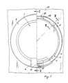
- Figure 1 is a diagrammatic front view of the door ready for use, with (in the right hand half) some parts shown in section or removed for greater clarity;
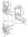
- Figure 2 is a diagrammatic section on the line II-II of Figure 1;
- Figure 3 is a diagrammatic section on the line III-III of Figure 1;
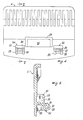
- Figure 4 is a view of a handle from below;
- Figure 5 is a section on the line v-v of Figure 4.
- With reference to the figures, the door comprises a substantially frusto-
conical window 1, anannular frame 2 on which the previously assembledcatch 23 and spring 26 can be seen, anannular bezel 3 and ahandle 4 for opening the door. Towards its front end, thewindow 1 comprises an outwardly projecting collar or flangedperiphery 5 arranged to cooperate with at least two substantially C-shaped regions 6 (see Figure 3 in particular), which project from an inner part of theframe 2 and are equidistant. - Each
region 6 comprises an inclinedupper part 7 and aledge 8, these being either continuous along the entire frame or alternating in order to simplify their moulding. There thus forms between the two arecess 9 of a certain angular width, into which thecollar 5 of thewindow 1 penetrates when by virtue of the elasticity of the plastics material of the frame, thewindow 1 is forced into this latter. - On the outer side of the
frame 2 there is a discontinuous wall orflange 11 comprising externally arim 12 with inclined or arcuate faces to facilitate the sliding of anouter wall 13 on thebezel 3, this wall comprising a hook-shaped portion at its end with its lower part 14 rounded and itsupper part 15 flat to allow the frame and bezel to be snap-fitted together (see Figure 3 in particular) by forcing this latter over the former. - The
bezel 3 comprises inwardly projecting, discontinuousequiradial walls 16 provided with arim 17 arranged to snap-cooperate with grooves orundercuts 18, which are shaped in such a manner as to retain said rim by engagement and are provided in discontinuous, radially more inner walls 18A of theframe 2. Further more innerequiradial walls 50 of thebezel 3 cooperate with the end part of thewindow 1, to lock it finally in the finished door. - This is also aided, with synergic action, by the
inner end 20 of thebezel 3, which acts on theouter side 19 of thewindow 1. Theframe 2 supports on a transverse pin 25, acatch 23 and a torsion spring 26 which urges the catch in a clockwise direction (with reference to Figure 2). The purpose of the catch is to keep the door closed, and for this purpose it penetrates into anaperture 21 in thewashing machine 43 and cooperates with the edges thereof. - The
catch 23 comprises an arm orappendix 28, which when the door is completely assembled rests on theend 29 of aninner part 30 of thehandle 4, this part being L-shaped in cross-section (Figure 2). - On the inner side of the
handle 4 there are also provided twoappendices 34 comprising, in a lateral position, tworeinforcement ribs 35 for ahead 36 and is arranged to snap-fit onto the pin 25 on which thecatch 23 is hinged. - On that side of the door opposite the
handle 4 there is provided ahinge 39 about which the door can rotate for its opening and closure. - The
hinge 39 comprises anarcuate arm 40 fixed at its end 41 to theframe 2, and a further arm 42 fixed to astructural part 43 of the washing machine The two arms are joined together by a pin 44. Thearm 40 andframe 2 are joined together by at least twoscrews 45. - Door assembly is commenced by fixing the
window 1 to theframe 2. This is done by forcing thewindow collar 5 so that it slides along theinclined walls 7 of theelement 6 of theframe 2 so as to insert saidcollar 5 into therecesses 9 in said elements. At this point thecatch 23 and spring 26 are positioned in theframe 2 by inserting the pin 25 into this latter, this being possible because of the presence of a corridor present in the frame 2 (not shown in the figure). The pin 25 is locked in position by one or more tangs provided in the frame, and also not shown, which can bend when the pin is moving in its direction of insertion, but not in the oppositie direction. However, this locking could be also attained by other means known to the expert of the art. The unit which has now been obtained is fixed to thehinge arm 40 by the screws 45 (the other arm 42 having been already fixed to the washing machine 43). - At this stage in the door assembly, the
window 1 has been inserted and axially locked in theregions 6 of theframe 2. The incomplete door is closed, and remains in its closed position by virtue of the engagement of thecatch 23 with theaperture 21, so that the washing machine can be subjected to its water-tightness test without the need for completing the door by fitting its optional aesthetic elements, namely thehandle 4 andbezel 3. The door assembly is completed by snap-forcing theouter end 13 of thebezel 3 over therim 11 present on the outside of theframe 2. - The handle is then fitted to the door. To do this, the
arm 28 of the catch 24 is raised by pressing against the end region of the catch so as to overcome the reaction force of the spring 26 which has been mounted on the pin 25 together with said catch.Said arm 28 is inserted into theinner cavity 33 of the L-shaped element 30 so that it interacts with thepart 29 of said element. At the same time, theopen side 38 of thebore 37 of theelement 33 is placed to coincide with the pin 25, and theelement 36 is then forced onto this latter so that thearm 28 of the catch 24 forces the L-shaped element 30 towards theframe 2. Thehandle 4 is thus fixed to the door.
Claims (8)
Applications Claiming Priority (2)
| Application Number | Priority Date | Filing Date | Title |
|---|---|---|---|
| IT8721707U IT210393Z2 (en) | 1987-06-02 | 1987-06-02 | PORTHOUSE FOR WASHING MACHINES AND SIMILAR HAVING AN INTERCHANGEABLE COUNTERFRAME AND MEANS SUITABLE TO GUARANTEE THE SEAL EVEN WITHOUT IT. |
| IT2170787U | 1987-06-02 |
Publications (2)
| Publication Number | Publication Date |
|---|---|
| EP0293984A1 true EP0293984A1 (en) | 1988-12-07 |
| EP0293984B1 EP0293984B1 (en) | 1991-12-27 |
Family
ID=11185719
Family Applications (1)
| Application Number | Title | Priority Date | Filing Date |
|---|---|---|---|
| EP88201076A Expired - Lifetime EP0293984B1 (en) | 1987-06-02 | 1988-05-31 | Door for washing machines and the like, with an interchangeable bezel and means for ensuring door tightness when the bezel is absent |
Country Status (3)
| Country | Link |
|---|---|
| EP (1) | EP0293984B1 (en) |
| DE (1) | DE3867129D1 (en) |
| IT (1) | IT210393Z2 (en) |
Cited By (17)
| Publication number | Priority date | Publication date | Assignee | Title |
|---|---|---|---|---|
| WO1993023601A1 (en) * | 1992-05-20 | 1993-11-25 | Miele & Cie. Gmbh & Co. | Textile washing machine with a door mounted on the washing unit so as to vibrate together with said unit |
| GB2320507A (en) * | 1996-12-02 | 1998-06-24 | Electrolux Zanussi Elettrodome | Door for a washing machine and/or drying machine |
| EP0859079A1 (en) * | 1997-02-17 | 1998-08-19 | CANDY S.p.A. | Hinge for electrical appliance door, particularly for laundry washing and/or drying machine |
| WO2003004754A1 (en) * | 2001-07-05 | 2003-01-16 | Arçelik, A. S. | Washing machine door |
| EP1281804A1 (en) * | 2001-08-02 | 2003-02-05 | Miele & Cie. GmbH & Co. | Front loading washing machine in particular for building into a fitted kitchen |
| EP1291459A1 (en) * | 2001-09-11 | 2003-03-12 | Whirlpool Corporation | Washing machine door for a front-load washing machine |
| WO2003057971A1 (en) * | 2002-01-09 | 2003-07-17 | Lg Electronics Inc. | Door for washing machine and dryer and washing machine and dryer having the same |
| EP1486604A2 (en) * | 2003-06-07 | 2004-12-15 | Samsung Electronics Co., Ltd. | Door locking mechanism |
| WO2006080788A1 (en) * | 2005-01-25 | 2006-08-03 | Lg Electronics Inc. | A door for a washing or drying machine |
| CN1317444C (en) * | 2002-01-09 | 2007-05-23 | Lg电子株式会社 | A door assembly and washing machine and dryer using the same |
| EP2000575A1 (en) | 2007-06-05 | 2008-12-10 | Samsung Electronics Co., Ltd. | Drum type washer and door |
| EP2098627A1 (en) | 2008-03-03 | 2009-09-09 | Miele & Cie. KG | Frontloading laundry treatment machine and door for a laundry treatment machine |
| US7617570B2 (en) | 2006-03-22 | 2009-11-17 | Whirlpool Corporation | Double-pivot, constrained kinematic hinge for a front-loading laundry machine |
| AU2006201708B2 (en) * | 2002-01-09 | 2010-03-25 | Lg Electronics Inc. | Hinge assembly for a door in a washing machine or a dryer |
| WO2016155785A1 (en) * | 2015-03-31 | 2016-10-06 | Arcelik Anonim Sirketi | Laundry washing machine having an improved leak-proof door assembly |
| EP3502341A1 (en) | 2017-12-22 | 2019-06-26 | Electrolux Appliances Aktiebolag | Laundry treatment machine |
| US11118295B2 (en) | 2017-11-16 | 2021-09-14 | Whirlpool Corporation | Laundry treating appliance having a user interface within a door assembly |
Families Citing this family (3)
| Publication number | Priority date | Publication date | Assignee | Title |
|---|---|---|---|---|
| KR100484795B1 (en) * | 2002-01-09 | 2005-04-22 | 엘지전자 주식회사 | The Door of A Drum Washer |
| CA2508860C (en) | 2005-05-30 | 2007-10-16 | Camco Inc. | Clothes dryer reversible door assembly |
| CA2508607C (en) | 2005-05-30 | 2007-09-11 | Camco Inc. | Clothes dryer door assembly |
Citations (3)
| Publication number | Priority date | Publication date | Assignee | Title |
|---|---|---|---|---|
| GB2115473A (en) * | 1982-02-08 | 1983-09-07 | Tokyo Shibaura Electric Co | Lid with a transparent panel |
| GB2118580A (en) * | 1982-04-16 | 1983-11-02 | Faini Spa | Window for washing machines |
| DE3603211A1 (en) * | 1986-02-03 | 1987-08-06 | Miele & Cie | Door for drum-type washing machines |
-
1987
- 1987-06-02 IT IT8721707U patent/IT210393Z2/en active
-
1988
- 1988-05-31 DE DE88201076T patent/DE3867129D1/en not_active Expired - Fee Related
- 1988-05-31 EP EP88201076A patent/EP0293984B1/en not_active Expired - Lifetime
Patent Citations (3)
| Publication number | Priority date | Publication date | Assignee | Title |
|---|---|---|---|---|
| GB2115473A (en) * | 1982-02-08 | 1983-09-07 | Tokyo Shibaura Electric Co | Lid with a transparent panel |
| GB2118580A (en) * | 1982-04-16 | 1983-11-02 | Faini Spa | Window for washing machines |
| DE3603211A1 (en) * | 1986-02-03 | 1987-08-06 | Miele & Cie | Door for drum-type washing machines |
Cited By (29)
| Publication number | Priority date | Publication date | Assignee | Title |
|---|---|---|---|---|
| WO1993023601A1 (en) * | 1992-05-20 | 1993-11-25 | Miele & Cie. Gmbh & Co. | Textile washing machine with a door mounted on the washing unit so as to vibrate together with said unit |
| GB2320507A (en) * | 1996-12-02 | 1998-06-24 | Electrolux Zanussi Elettrodome | Door for a washing machine and/or drying machine |
| GB2320507B (en) * | 1996-12-02 | 2000-12-06 | Electrolux Zanussi Elettrodome | Door handle cover for a washing/drying machine |
| EP0859079A1 (en) * | 1997-02-17 | 1998-08-19 | CANDY S.p.A. | Hinge for electrical appliance door, particularly for laundry washing and/or drying machine |
| WO2003004754A1 (en) * | 2001-07-05 | 2003-01-16 | Arçelik, A. S. | Washing machine door |
| EP1281804A1 (en) * | 2001-08-02 | 2003-02-05 | Miele & Cie. GmbH & Co. | Front loading washing machine in particular for building into a fitted kitchen |
| US6966204B2 (en) | 2001-09-11 | 2005-11-22 | Whirlpool Corporation | Washing machine door for a front-load washing machine |
| EP1291459A1 (en) * | 2001-09-11 | 2003-03-12 | Whirlpool Corporation | Washing machine door for a front-load washing machine |
| CN1317444C (en) * | 2002-01-09 | 2007-05-23 | Lg电子株式会社 | A door assembly and washing machine and dryer using the same |
| AU2003202154B2 (en) * | 2002-01-09 | 2006-04-27 | Lg Electronics Inc. | Door for washing machine and dryer and washing machine and dryer having the same |
| AU2003202154B8 (en) * | 2002-01-09 | 2006-05-25 | Lg Electronics Inc. | Door for washing machine and dryer and washing machine and dryer having the same |
| CN1314851C (en) * | 2002-01-09 | 2007-05-09 | Lg电子株式会社 | Door for washing machine and dryer and washing machine and dryer having the same |
| WO2003057971A1 (en) * | 2002-01-09 | 2003-07-17 | Lg Electronics Inc. | Door for washing machine and dryer and washing machine and dryer having the same |
| US7581414B2 (en) | 2002-01-09 | 2009-09-01 | Lg Electronics Inc. | Door for washing machine and dryer and washing machine and dryer having the same |
| AU2006201708B2 (en) * | 2002-01-09 | 2010-03-25 | Lg Electronics Inc. | Hinge assembly for a door in a washing machine or a dryer |
| EP1486604A2 (en) * | 2003-06-07 | 2004-12-15 | Samsung Electronics Co., Ltd. | Door locking mechanism |
| EP1486604A3 (en) * | 2003-06-07 | 2008-11-05 | Samsung Electronics Co., Ltd. | Door locking mechanism |
| WO2006080788A1 (en) * | 2005-01-25 | 2006-08-03 | Lg Electronics Inc. | A door for a washing or drying machine |
| US7934404B2 (en) | 2005-01-25 | 2011-05-03 | Lg Electronics Inc. | Door for a washing or drying machine |
| US7617570B2 (en) | 2006-03-22 | 2009-11-17 | Whirlpool Corporation | Double-pivot, constrained kinematic hinge for a front-loading laundry machine |
| US7765839B2 (en) | 2007-06-05 | 2010-08-03 | Samsung Electronics Co., Ltd. | Drum type washer and door |
| EP2000575A1 (en) | 2007-06-05 | 2008-12-10 | Samsung Electronics Co., Ltd. | Drum type washer and door |
| CN101319455B (en) * | 2007-06-05 | 2012-01-04 | 三星电子株式会社 | Drum type washer and door |
| EP2098627A1 (en) | 2008-03-03 | 2009-09-09 | Miele & Cie. KG | Frontloading laundry treatment machine and door for a laundry treatment machine |
| WO2016155785A1 (en) * | 2015-03-31 | 2016-10-06 | Arcelik Anonim Sirketi | Laundry washing machine having an improved leak-proof door assembly |
| US11118295B2 (en) | 2017-11-16 | 2021-09-14 | Whirlpool Corporation | Laundry treating appliance having a user interface within a door assembly |
| US11959220B2 (en) | 2017-11-16 | 2024-04-16 | Whirlpool Corporation | Laundry treating appliance having a user interface within a door assembly |
| EP3502341A1 (en) | 2017-12-22 | 2019-06-26 | Electrolux Appliances Aktiebolag | Laundry treatment machine |
| WO2019120979A1 (en) | 2017-12-22 | 2019-06-27 | Electrolux Appliances Aktiebolag | Laundry treatment machine |
Also Published As
| Publication number | Publication date |
|---|---|
| DE3867129D1 (en) | 1992-02-06 |
| EP0293984B1 (en) | 1991-12-27 |
| IT210393Z2 (en) | 1988-12-30 |
| IT8721707V0 (en) | 1987-06-02 |
Similar Documents
| Publication | Publication Date | Title |
|---|---|---|
| EP0293984B1 (en) | Door for washing machines and the like, with an interchangeable bezel and means for ensuring door tightness when the bezel is absent | |
| EP1507034A2 (en) | Appliance doors | |
| US20030067254A1 (en) | Molded plastic dishwasher door assembly | |
| US6761049B2 (en) | Sealing sleeve | |
| US20030000267A1 (en) | Combined mechanical and electronic key, in particular for locks in a vehicle | |
| EP1736418A2 (en) | Hinge particularly for box-like bodies | |
| EP1397816A1 (en) | Control panel assembly for home appliances and method for manufacturing the same | |
| CA1262703A (en) | Plastic stopper with a snap hinge | |
| RU2040687C1 (en) | Link body | |
| US20030172689A1 (en) | Laundry appliance | |
| CA1201262A (en) | Hinge | |
| US6971531B1 (en) | Two-part plastic snap hinge closure | |
| US5611610A (en) | Control housing | |
| AU629707B2 (en) | Assembly language programming potential error detection scheme sensing apparent inconsistency with a previous operation | |
| EP0317988B1 (en) | A process for the assembly of a motor vehicle door and a door obtained by such process | |
| EP0917853A1 (en) | Door locking arrangement for a household appliance, such as for example a dishwashing machine | |
| US5347687A (en) | Hinge housing | |
| EP3064634A1 (en) | Laundry treatment appliance | |
| JPH0845610A (en) | Plug connector that can be locked | |
| AU1760200A (en) | A lid for a cooking appliance | |
| CA2395092C (en) | Ribbed escutcheon for appliance door assembly | |
| EP0731244B1 (en) | Mobile accommodation and window for use therein | |
| GB2411431A (en) | Lever-operated expansion fastenings for hinge parts | |
| ITBO20080773A1 (en) | HANDLE CONNECTION DEVICE, IN PARTICULAR OF HANDLES WITH TUB. | |
| ITMI940189U1 (en) | IMPROVEMENTS TO THE HOUSING OF THE DOOR CLOSING HOOK IN WASHING MACHINES |
Legal Events
| Date | Code | Title | Description |
|---|---|---|---|
| PUAI | Public reference made under article 153(3) epc to a published international application that has entered the european phase |
Free format text: ORIGINAL CODE: 0009012 |
|
| AK | Designated contracting states |
Kind code of ref document: A1 Designated state(s): DE FR GB |
|
| RAP1 | Party data changed (applicant data changed or rights of an application transferred) |
Owner name: WHIRLPOOL INTERNATIONAL B.V. |
|
| 17P | Request for examination filed |
Effective date: 19890525 |
|
| 17Q | First examination report despatched |
Effective date: 19901119 |
|
| GRAA | (expected) grant |
Free format text: ORIGINAL CODE: 0009210 |
|
| AK | Designated contracting states |
Kind code of ref document: B1 Designated state(s): DE FR GB |
|
| REF | Corresponds to: |
Ref document number: 3867129 Country of ref document: DE Date of ref document: 19920206 |
|
| ET | Fr: translation filed | ||
| PLBE | No opposition filed within time limit |
Free format text: ORIGINAL CODE: 0009261 |
|
| STAA | Information on the status of an ep patent application or granted ep patent |
Free format text: STATUS: NO OPPOSITION FILED WITHIN TIME LIMIT |
|
| 26N | No opposition filed | ||
| PGFP | Annual fee paid to national office [announced via postgrant information from national office to epo] |
Ref country code: FR Payment date: 19980511 Year of fee payment: 11 |
|
| PGFP | Annual fee paid to national office [announced via postgrant information from national office to epo] |
Ref country code: GB Payment date: 19980522 Year of fee payment: 11 |
|
| PGFP | Annual fee paid to national office [announced via postgrant information from national office to epo] |
Ref country code: DE Payment date: 19980608 Year of fee payment: 11 |
|
| PG25 | Lapsed in a contracting state [announced via postgrant information from national office to epo] |
Ref country code: GB Free format text: LAPSE BECAUSE OF NON-PAYMENT OF DUE FEES Effective date: 19990531 |
|
| GBPC | Gb: european patent ceased through non-payment of renewal fee |
Effective date: 19990531 |
|
| PG25 | Lapsed in a contracting state [announced via postgrant information from national office to epo] |
Ref country code: FR Free format text: LAPSE BECAUSE OF NON-PAYMENT OF DUE FEES Effective date: 20000131 |
|
| PG25 | Lapsed in a contracting state [announced via postgrant information from national office to epo] |
Ref country code: DE Free format text: LAPSE BECAUSE OF NON-PAYMENT OF DUE FEES Effective date: 20000301 |
|
| REG | Reference to a national code |
Ref country code: FR Ref legal event code: ST |