EP1507034A2 - Appliance doors - Google Patents
Appliance doors Download PDFInfo
- Publication number
- EP1507034A2 EP1507034A2 EP04018994A EP04018994A EP1507034A2 EP 1507034 A2 EP1507034 A2 EP 1507034A2 EP 04018994 A EP04018994 A EP 04018994A EP 04018994 A EP04018994 A EP 04018994A EP 1507034 A2 EP1507034 A2 EP 1507034A2
- Authority
- EP
- European Patent Office
- Prior art keywords
- structural panel
- panel
- outer peripheral
- annular members
- annular
- Prior art date
- Legal status (The legal status is an assumption and is not a legal conclusion. Google has not performed a legal analysis and makes no representation as to the accuracy of the status listed.)
- Withdrawn
Links
Images


Classifications
-
- D—TEXTILES; PAPER
- D06—TREATMENT OF TEXTILES OR THE LIKE; LAUNDERING; FLEXIBLE MATERIALS NOT OTHERWISE PROVIDED FOR
- D06F—LAUNDERING, DRYING, IRONING, PRESSING OR FOLDING TEXTILE ARTICLES
- D06F39/00—Details of washing machines not specific to a single type of machines covered by groups D06F9/00 - D06F27/00
- D06F39/12—Casings; Tubs
- D06F39/14—Doors or covers; Securing means therefor
-
- D—TEXTILES; PAPER
- D06—TREATMENT OF TEXTILES OR THE LIKE; LAUNDERING; FLEXIBLE MATERIALS NOT OTHERWISE PROVIDED FOR
- D06F—LAUNDERING, DRYING, IRONING, PRESSING OR FOLDING TEXTILE ARTICLES
- D06F37/00—Details specific to washing machines covered by groups D06F21/00 - D06F25/00
- D06F37/02—Rotary receptacles, e.g. drums
- D06F37/04—Rotary receptacles, e.g. drums adapted for rotation or oscillation about a horizontal or inclined axis
- D06F37/10—Doors; Securing means therefor
-
- D—TEXTILES; PAPER
- D06—TREATMENT OF TEXTILES OR THE LIKE; LAUNDERING; FLEXIBLE MATERIALS NOT OTHERWISE PROVIDED FOR
- D06F—LAUNDERING, DRYING, IRONING, PRESSING OR FOLDING TEXTILE ARTICLES
- D06F37/00—Details specific to washing machines covered by groups D06F21/00 - D06F25/00
- D06F37/26—Casings; Tubs
- D06F37/28—Doors; Security means therefor
-
- D—TEXTILES; PAPER
- D06—TREATMENT OF TEXTILES OR THE LIKE; LAUNDERING; FLEXIBLE MATERIALS NOT OTHERWISE PROVIDED FOR
- D06F—LAUNDERING, DRYING, IRONING, PRESSING OR FOLDING TEXTILE ARTICLES
- D06F37/00—Details specific to washing machines covered by groups D06F21/00 - D06F25/00
- D06F37/42—Safety arrangements, e.g. for stopping rotation of the receptacle upon opening of the casing door
-
- F—MECHANICAL ENGINEERING; LIGHTING; HEATING; WEAPONS; BLASTING
- F24—HEATING; RANGES; VENTILATING
- F24C—DOMESTIC STOVES OR RANGES ; DETAILS OF DOMESTIC STOVES OR RANGES, OF GENERAL APPLICATION
- F24C15/00—Details
- F24C15/02—Doors specially adapted for stoves or ranges
- F24C15/04—Doors specially adapted for stoves or ranges with transparent panels
Definitions
- the invention is directed to a door or lid for appliances, particularly for "white” goods, such as washers, but can also be utilized in conjunction with dryers or with "brown” appliances, such as a microwave ovens.
- washer doors Conventionally, washer doors have been made of metal with or without a glass panel through which the interior of the washer and its contents can be viewed.
- UK Patent Application GB 2 118 580 describes conventional washer doors for washing machines which each include a piece of glass secured to a circumferential annular support formed of nesting sections by means of screws.
- an annular support for the glass window of the washing machine door is formed of two complementary annular rings or frames which nest together and have two inboardmost flanges or opposing portions between which the circumferential outer edge of the glass is secured after the two rings have been joined together.
- the washing machine door is essentially constructed from two separate annular rings and a piece of glass which are snap-secured to each other.
- UK Patent Application GB 2 294 698 A acknowledges the existence in the prior art of a clothes washing machine door which includes two plastic rings but these are completely absent in the latter disclosure and instead the washer door is defined by a central wall member to which is glued a hinge and a catch. Since the entire door is made from transparent material, a layer of opaque material is applied to the part of the wall member to which the hinge and catch are attached in order to prevent the latter components from being viewed from the exterior.
- U.S. Patent No. 6,539,753 B1 discloses a drum-type washing machine having a cabinet with a front circular access opening which is accessible by opening a door of a circular shape which has a central transparent portion made of glass, for example.
- the specifics of the construction of the door are only illustrated schematically and are not described.
- U.S. Patent Application Publication No. 2003/0046964 A1 discloses a conventional door having a transparent cover, most likely plastic, which is secured by a snap-assembly to a front frame and a gallows frame which allows viewing the washer interior. This might be a representative example of the schematically illustrated door of U.S. Patent No. 6, 539,753 B1.
- U.S. Patent No. 3,276,229 is an example of a relatively old washer door having a sleeve-like peripheral window portion with an edge of a glass panel being secured to a metallic door structure.
- Metal washer doors with glass windows made from enumerable metallic components screwed or bolted together remain commonplace in the industry and share many of the same disadvantages, most notable among which are the high cost of manufacturing and inevitable rusting and attendant leakage when in use.
- U.S. Patent No. 6,256,823 B1 discloses a door of a front-loading washing machine which has an annular front and an inwardly or rearwardly sloping back of lesser diameter and, on some models, a transparent window to allow the user to view the washing operation.
- the patent discloses but does not describe a peripheral interconnection between an edge of the transparent window and an unnumbered C-shaped channel in an inboard edge of a sloping back of the door.
- U.S. Patent Nos. 2,394,176 and 3,489,135 are each directed to an oven door construction but are included herein as exemplary of many door constructions utilizing two glass panels.
- U.S. Patent No. 4,934,559 discloses a clothes dryer having a front-loading glass door including a window united to a ring using a door glass seal or gasket.
- the washer door of the present invention includes a transparent panel constructed from tempered glass and an open frame, border or encapsulation constructed of polymeric/copolymeric synthetic plastic material.
- An outer peripheral edge of the tempered glass has injection molded thereto an innermost edge of the frame, border or encapsulation and a peripheral flange of the frame is provided with an appropriate hinge, catch and peripheral seal.
- a second outermost frame is secured in overlying relationship to the flange of the inner frame which effects an aesthetically pleasing outer appearance of the washer door.
- the two frames are preferably each made of polymeric/copolymeric plastic material and are preferably snap-secured together, but the outer frame can also be made of sheet metal or the like and can be secured to the inner frame by conventional fasteners, such as screws, bolts and nuts, etc.
- the washer door particularly when constructed from two polymeric/copolymeric frames or borders with the tempered glass encapsulated thereto, results in a virtually indestructible washer door which is leak-proof, rust-proof, effects low maintenance, is virtually indestructible, and achieves exceptionable aesthetics at modest costs.
- the washer door may be provided with a second glass panel carried by the outermost frame which is preferably united thereto through an injection molded peripheral edge encapsulation.
- the inner frame and its glass panel and the outer frame and its glass panel are each a unitary structure which can be readily, rapidly and inexpensively secured to each other and disassembled should such be required for purposes of gasket and/or desiccant replacement.
- a washer door may also be constructed from an inner frame and an outer frame with the inner frame having encapsulated thereto an edge of a concave/convex piece or panel of glass while the outer frame has an inner flange to which is glued an edge of a planar piece of glass.
- the concave/convex glass not only affords visual access to the washer interior, but affords tumbling action to the clothing as it is being washed.
- FIGURE 1 is a fragmentary front perspective view, and illustrates a clothes washer having an opening closed by a washer door or lid of the present invention hinged thereto with an outer frame defining an opening through which clothing in the washer can be viewed through a tempered glass panel peripherally encapsulated to an inner periphery of a polymeric/copolymeric plastic material inner frame.
- FIGURE 2 is an exploded view, and illustrates the inner and outer frames and a gasket prior to the assembly thereof.
- FIGURE 3 is an enlarged cross-sectional view taken generally along line 3-3 of Figure 1, and illustrates the relationship of the inner and outer frames to each other and the assembly thereof.
- FIGURE 4 is a cross-sectional view taken generally along line 4-4 of Figure 3, and illustrates hooks and slots carried by respective inboard walls of the outer and inner frames for snap-securing the same together.
- FIGURE 5 is an enlarged fragmentary view of the encircled portion of Figure 4, and illustrates a pair of hooks or tongues of an inner wall of the outer frame received in a slot of an inner wall of the inner frame.
- FIGURE 6 is a fragmentary cross-sectional view taken generally along line 6-6 of Figure 5, and illustrates details of the interlocked connection between the pair of hooks or tongues and the associated slot.
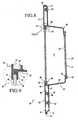
- FIGURE 7 is a fragmentary perspective view of another clothes washer, and illustrates another door of the invention in its closed position.
- FIGURE 8 is an enlarged cross-sectional view taken generally along line 8-8 of Figure 7, and illustrates inner and outer frames of the washer door snap-secured to each other with each frame having an innermost peripheral edge encapsulated through injection molding to an associated peripheral edge of a tempered glass panel.
- FIGURE 9 is an enlarged fragmentary view of the encircled portion of Figure 8, and illustrates details thereof.
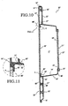
- FIGURE 10 is a cross-sectional view through another washer door of the present invention similar to Figure 8, but illustrates an outer frame to which a tempered glass panel is bonded.
- FIGURE 11 is a fragmentary enlarged view of the encircled portion of Figure 10, and illustrates details thereof.
- FIGURE 12 is a cross-sectional view taken through another washer door of the present invention similar to the washer doors of Figures 8 and 10, and illustrates a concave/convex piece of tempered glass having an edge encapsulated through injection molding to an inner frame of the washer door and an outer planar tempered glass panel bonded to an outer frame of the washer door.
- a washer 10 is illustrated in Figure 1 of the drawings and includes a conventional washer body 11 having an interior tub or chamber 12 to which is hinged by a pair of conventional hinges 14 a novel clothes washer door or lid 20 of the present invention.
- a conventional agitator (not shown) is mounted in the tub or chamber 12 and reciprocates arcuately in a conventional fashion during a clothes washing cycle.
- the washer door 20 includes three major components, namely, a tempered glass panel 21, an inner frame, encapsulation or border 30 and an outer frame, encapsulation or border 50.
- the tempered glass panel 21 is of a predetermined peripheral configuration defined by a substantially continuous peripheral edge 22.
- the glass panel 21 further includes opposite inner and outer surfaces 23, 24, respectively, bridged by the peripheral edge 22 ( Figures 3 and 4).
- An outermost peripheral edge portion 25 of the piece of glass or glass panel 21 is defined by the peripheral edge 22 and immediately adjacent surface portions (unnumbered) of the opposite inner outer surfaces 23, 24, respectively.
- the inner open frame, encapsulation or border 30 is formed as a one-piece, injection molded, polymeric/copolymeric synthetic plastic material annular member and includes an outer peripheral portion, peripheral skirt or peripheral wall 31, an innermost portion 32 entirely encapsulating the outer peripheral edge portion 25 of the glass panel 21, an outermost peripheral flange 33 and a peripheral body wall 34.
- the peripheral body wall 34 blends with the inner peripheral portion 32 at a radius portion or radius wall 35 and similarly blends or merges with the peripheral flange 33 at a peripheral radius portion or radius wall 36.
- An axially outwardly projecting peripheral wall 37 ( Figures 3 - 5) is an extension of the body wall 34 and projects axially outwardly beyond the peripheral flange 33 and substantially normal thereto ( Figure 5), and projecting therefrom in peripherally spaced relationship to each other are a plurality of identical latching or securing tabs or fingers 38 ( Figures 2, 5 and 6) each having a generally polygonal latching opening, slot or aperture 41 therein.
- a sealing gasket 60 ( Figure 2) corresponding to the configuration of the channel 42 is seated in the latter with portions 61 of the sealing gasket 60 being forced through the slots 44 to thereby retain the sealing gasket 60 seated within the channel 42 with a gasket sealing surface 65 of the sealing gasket 60 positioned to peripherally contact and seal against an outer surface (unnumbered) of the washer body 11 in the closed position of the washer door 20 ( Figure 1) to prevent leakage of water during a washing cycle.
- the inner peripheral wall 53 of the outer frame 50 includes eight pairs of latching teeth, tabs or tongues 55 ( Figures 5 and 6) which engage by pairs in each of the polygonal latching openings 41 of the inner frame member 30 in the manner best illustrated in Figures 5 and 6 of the drawings to maintain the inner and outer frames 30, 50, respectively, in snap-secured assembled relationship.
- the walls 37, 53 ( Figure 5) of the respective inner and outer frames 30, 50 are stepped to provide a smooth transition between the outer surfaces (unnumbered) of the peripheral body wall 34 of the inner frame 30 and the inner peripheral wall 53 of the outer frame 50.
- the outer frame 50' is formed as an integral injection-molded encapsulation of synthetic polymeric/copolymeric plastic material and includes a peripheral encapsulation edge 80 which includes outer and inner peripheral walls 81, 82, respectively, between which is encapsulated an outermost peripheral edge 86 of a piece or panel of tempered glass 85 which with the glass panel 21', the body wall 34' and the radius 36' define a cavity or chamber C' ( Figure 8) through which the interior of the washer tub or chamber 12' and the clothing therein can be viewed.
- a peripheral encapsulation edge 80 which includes outer and inner peripheral walls 81, 82, respectively, between which is encapsulated an outermost peripheral edge 86 of a piece or panel of tempered glass 85 which with the glass panel 21', the body wall 34' and the radius 36' define a cavity or chamber C' ( Figure 8) through which the interior of the washer tub or chamber 12' and the clothing therein can be viewed.
- a peripheral annular band 87" of desiccant material is held in sandwiched relationship between opposing grooves (unnumbered) formed in opposing circumferential projections 88", 89" integrally formed upon the injection molding of the inner frame 30" and the outer frame 50". Any moist air within the chamber C" readily migrates through gaps or spaces between the peripheral walls 37", 53" and the respective latching openings and tabs (not shown) associated therewith corresponding to the structure shown in Figure 5.
Landscapes
- Engineering & Computer Science (AREA)
- Textile Engineering (AREA)
- Chemical & Material Sciences (AREA)
- Combustion & Propulsion (AREA)
- Mechanical Engineering (AREA)
- General Engineering & Computer Science (AREA)
- Main Body Construction Of Washing Machines And Laundry Dryers (AREA)
- Detail Structures Of Washing Machines And Dryers (AREA)
Abstract
Description
- The invention is directed to a door or lid for appliances, particularly for "white" goods, such as washers, but can also be utilized in conjunction with dryers or with "brown" appliances, such as a microwave ovens. Conventionally, washer doors have been made of metal with or without a glass panel through which the interior of the washer and its contents can be viewed.
- UK Patent Application GB 2 118 580 describes conventional washer doors for washing machines which each include a piece of glass secured to a circumferential annular support formed of nesting sections by means of screws. In such conventional constructions, it is found very difficult to secure the glass to the annular support by means of separate support sections because the edge of the glass is very often irregular and cannot therefore be fitted correctly to the support. In order to avoid the latter and other problems, an annular support for the glass window of the washing machine door is formed of two complementary annular rings or frames which nest together and have two inboardmost flanges or opposing portions between which the circumferential outer edge of the glass is secured after the two rings have been joined together. The rings are joined together by peripherally innermost and outermost beads, projections or ribs which interconnect with grooves or ribs. Therefore, the washing machine door is essentially constructed from two separate annular rings and a piece of glass which are snap-secured to each other.
- UK Patent Application GB 2 294 698 A acknowledges the existence in the prior art of a clothes washing machine door which includes two plastic rings but these are completely absent in the latter disclosure and instead the washer door is defined by a central wall member to which is glued a hinge and a catch. Since the entire door is made from transparent material, a layer of opaque material is applied to the part of the wall member to which the hinge and catch are attached in order to prevent the latter components from being viewed from the exterior.
- U.S. Patent No. 6,539,753 B1 discloses a drum-type washing machine having a cabinet with a front circular access opening which is accessible by opening a door of a circular shape which has a central transparent portion made of glass, for example. The specifics of the construction of the door are only illustrated schematically and are not described.
- U.S. Patent Application Publication No. 2003/0046964 A1 discloses a conventional door having a transparent cover, most likely plastic, which is secured by a snap-assembly to a front frame and a gallows frame which allows viewing the washer interior. This might be a representative example of the schematically illustrated door of U.S. Patent No. 6, 539,753 B1.
- U.S. Patent No. 3,276,229 is an example of a relatively old washer door having a sleeve-like peripheral window portion with an edge of a glass panel being secured to a metallic door structure. Metal washer doors with glass windows made from enumerable metallic components screwed or bolted together remain commonplace in the industry and share many of the same disadvantages, most notable among which are the high cost of manufacturing and inevitable rusting and attendant leakage when in use.
- U.S. Patent No. 6,256,823 B1 discloses a door of a front-loading washing machine which has an annular front and an inwardly or rearwardly sloping back of lesser diameter and, on some models, a transparent window to allow the user to view the washing operation. The patent discloses but does not describe a peripheral interconnection between an edge of the transparent window and an unnumbered C-shaped channel in an inboard edge of a sloping back of the door.
- U.S. Patent Nos. 2,394,176 and 3,489,135 are each directed to an oven door construction but are included herein as exemplary of many door constructions utilizing two glass panels.
- U.S. Patent No. 4,934,559 discloses a clothes dryer having a front-loading glass door including a window united to a ring using a door glass seal or gasket.
- A number of other patents developed during a search of the present invention are listed herein as reflective of the state of the art.
Re 19,752 Glasser 2,140,433 Paul 2,580,957 Reeves 2,650,490 Glassey 3,367,730 Andrews et al. 3,384,072 Davis et al. 3,877,460 Lotz et al. 4,033,322 Seidel 4,364,533 Pompei et al. 4,403,128 Takagi et al. 4,522,311 Ikeda 4,892,085 Salvi 5,022,380 Faurel et al. 5,496,104 Arnold et al. 5,570,597 Bongini et al. 5,881,710 Davis et al. 6,135,130 Martineau 6,442,981 B1 Augustsson 6,508,085 B1 Byrne - The present invention is specifically directed to a clothes washer door for a clothes washer, but contrary to the latter-described conventional doors and those of the listed patents, the washer door of the present invention includes a transparent panel constructed from tempered glass and an open frame, border or encapsulation constructed of polymeric/copolymeric synthetic plastic material. An outer peripheral edge of the tempered glass has injection molded thereto an innermost edge of the frame, border or encapsulation and a peripheral flange of the frame is provided with an appropriate hinge, catch and peripheral seal. A second outermost frame is secured in overlying relationship to the flange of the inner frame which effects an aesthetically pleasing outer appearance of the washer door. The two frames are preferably each made of polymeric/copolymeric plastic material and are preferably snap-secured together, but the outer frame can also be made of sheet metal or the like and can be secured to the inner frame by conventional fasteners, such as screws, bolts and nuts, etc.
- The washer door, particularly when constructed from two polymeric/copolymeric frames or borders with the tempered glass encapsulated thereto, results in a virtually indestructible washer door which is leak-proof, rust-proof, effects low maintenance, is virtually indestructible, and achieves exceptionable aesthetics at modest costs.
- In further accordance with the present invention, the washer door may be provided with a second glass panel carried by the outermost frame which is preferably united thereto through an injection molded peripheral edge encapsulation. In this case, the inner frame and its glass panel and the outer frame and its glass panel are each a unitary structure which can be readily, rapidly and inexpensively secured to each other and disassembled should such be required for purposes of gasket and/or desiccant replacement.
- In further accordance with this invention, a washer door may also be constructed from an inner frame and an outer frame with the inner frame having encapsulated thereto an edge of a concave/convex piece or panel of glass while the outer frame has an inner flange to which is glued an edge of a planar piece of glass. The concave/convex glass not only affords visual access to the washer interior, but affords tumbling action to the clothing as it is being washed.
- With the above and other objects in view that will hereinafter appear, the nature of the invention will be more clearly understood by reference to the following detailed description, the appended claims and the several views illustrated in the accompanying drawings.
- FIGURE 1 is a fragmentary front perspective view, and illustrates a clothes washer having an opening closed by a washer door or lid of the present invention hinged thereto with an outer frame defining an opening through which clothing in the washer can be viewed through a tempered glass panel peripherally encapsulated to an inner periphery of a polymeric/copolymeric plastic material inner frame.
- FIGURE 2 is an exploded view, and illustrates the inner and outer frames and a gasket prior to the assembly thereof.
- FIGURE 3 is an enlarged cross-sectional view taken generally along line 3-3 of Figure 1, and illustrates the relationship of the inner and outer frames to each other and the assembly thereof.
- FIGURE 4 is a cross-sectional view taken generally along line 4-4 of Figure 3, and illustrates hooks and slots carried by respective inboard walls of the outer and inner frames for snap-securing the same together.
- FIGURE 5 is an enlarged fragmentary view of the encircled portion of Figure 4, and illustrates a pair of hooks or tongues of an inner wall of the outer frame received in a slot of an inner wall of the inner frame.
- FIGURE 6 is a fragmentary cross-sectional view taken generally along line 6-6 of Figure 5, and illustrates details of the interlocked connection between the pair of hooks or tongues and the associated slot.
- FIGURE 7 is a fragmentary perspective view of another clothes washer, and illustrates another door of the invention in its closed position.
- FIGURE 8 is an enlarged cross-sectional view taken generally along line 8-8 of Figure 7, and illustrates inner and outer frames of the washer door snap-secured to each other with each frame having an innermost peripheral edge encapsulated through injection molding to an associated peripheral edge of a tempered glass panel.
- FIGURE 9 is an enlarged fragmentary view of the encircled portion of Figure 8, and illustrates details thereof.
- FIGURE 10 is a cross-sectional view through another washer door of the present invention similar to Figure 8, but illustrates an outer frame to which a tempered glass panel is bonded.
- FIGURE 11 is a fragmentary enlarged view of the encircled portion of Figure 10, and illustrates details thereof.
- FIGURE 12 is a cross-sectional view taken through another washer door of the present invention similar to the washer doors of Figures 8 and 10, and illustrates a concave/convex piece of tempered glass having an edge encapsulated through injection molding to an inner frame of the washer door and an outer planar tempered glass panel bonded to an outer frame of the washer door.
- A
washer 10 is illustrated in Figure 1 of the drawings and includes aconventional washer body 11 having an interior tub orchamber 12 to which is hinged by a pair of conventional hinges 14 a novel clothes washer door orlid 20 of the present invention. A conventional agitator (not shown) is mounted in the tub orchamber 12 and reciprocates arcuately in a conventional fashion during a clothes washing cycle. - The
washer door 20 includes three major components, namely, atempered glass panel 21, an inner frame, encapsulation orborder 30 and an outer frame, encapsulation orborder 50. - The
tempered glass panel 21 is of a predetermined peripheral configuration defined by a substantially continuousperipheral edge 22. Theglass panel 21 further includes opposite inner andouter surfaces peripheral edge portion 25 of the piece of glass orglass panel 21 is defined by theperipheral edge 22 and immediately adjacent surface portions (unnumbered) of the opposite innerouter surfaces - The inner open frame, encapsulation or
border 30 is formed as a one-piece, injection molded, polymeric/copolymeric synthetic plastic material annular member and includes an outer peripheral portion, peripheral skirt orperipheral wall 31, aninnermost portion 32 entirely encapsulating the outerperipheral edge portion 25 of theglass panel 21, an outermostperipheral flange 33 and aperipheral body wall 34. Theperipheral body wall 34 blends with the innerperipheral portion 32 at a radius portion orradius wall 35 and similarly blends or merges with theperipheral flange 33 at a peripheral radius portion orradius wall 36. - An axially outwardly projecting peripheral wall 37 (Figures 3 - 5) is an extension of the
body wall 34 and projects axially outwardly beyond theperipheral flange 33 and substantially normal thereto (Figure 5), and projecting therefrom in peripherally spaced relationship to each other are a plurality of identical latching or securing tabs or fingers 38 (Figures 2, 5 and 6) each having a generally polygonal latching opening, slot oraperture 41 therein. Theperipheral flange 33 of the frame orannular member 30 includes an inwardly opening substantially continuous channel 42 (Figure 3) defined by a generally inwardly openingU-shaped wall 43 provided along its bottom (unnumbered) with a plurality of spaced slots 44 (Figure 2) and betweenadjacent slots 44 are inwardly opening generally U-shaped wall portions 45 (Figure 2). A sealing gasket 60 (Figure 2) corresponding to the configuration of thechannel 42 is seated in the latter withportions 61 of the sealinggasket 60 being forced through theslots 44 to thereby retain the sealinggasket 60 seated within thechannel 42 with agasket sealing surface 65 of the sealinggasket 60 positioned to peripherally contact and seal against an outer surface (unnumbered) of thewasher body 11 in the closed position of the washer door 20 (Figure 1) to prevent leakage of water during a washing cycle. - The peripheral skirt or
peripheral wall 31 of theinner frame 30 is disposed substantially normal to theperipheral flange 33 along the upper and side edges (unnumbered in Figure 1) of thedoor 20, as is designated appropriately by thereference numeral 69 in Figures 1 and 2, but at the bottom edge a portion 70 (Figures 2 and 3) of theperipheral wall 31 tapers upwardly at an approximately 45 degree angle and outwardly therefrom. - The outer frame or
annular member 50 includes anannular wall 51, an outerperipheral wall 52 and an innerperipheral wall 53. The outerperipheral wall 52 is substantially normal to theannular wall 51 along the upper and side edges (unnumbered) of thedoor 20 but at the bottom edge a wall portion 54 (Figure 3) is formed into an inwardly opening hook which engages the bottom wall portion 70 (Figure 3) of theinner frame 30 and defines therewith a finger grip area FG (Figure 3) running along the bottom of thedoor 20 which can be gripped by a user to open and close thedoor 20. The innerperipheral wall 53 of theouter frame 50 includes eight pairs of latching teeth, tabs or tongues 55 (Figures 5 and 6) which engage by pairs in each of thepolygonal latching openings 41 of theinner frame member 30 in the manner best illustrated in Figures 5 and 6 of the drawings to maintain the inner andouter frames walls 37, 53 (Figure 5) of the respective inner andouter frames peripheral body wall 34 of theinner frame 30 and the innerperipheral wall 53 of theouter frame 50. Since the material of theouter frame 50 is preferably relatively resilient polymeric/copolymeric material, but can also be sheet metal, a tool, such as the blade B (Figure 5) of a screwdriver, can be inserted at the juncture (unnumbered) of thewalls outer frames peripheral wall 53 sufficiently to progressively disengage the pairs of tongues ornotches 55 from thegrooves 41 to dissasemble theframes gasket 60. Furthermore, theannular wall 51 of theouter frame 50 rests upon the U-shaped wall portions orchannels 45 and is supported thereby to impart further rigidity/integrity to theoverall washer door 20. - Reference is made to Figures 7 through 9 of the drawings and another washer 10' (Figure 7) which includes a conventional washer body 11' having an interior tub or chamber 12' and a washer door or lid 20'. All structure of the washer 10' which is identical to structure of the
washer 10 has been primed to thereby incorporate by reference such identical structure into the description of the washer 10' and washer door 20' thereof. - The washer door 20' includes three major components, namely, a tempered glass panel 21', an inner frame, encapsulation or border 30', and an outer frame, border, annular member or encapsulation 50'. The outer frame 50' includes an annular flange 51', an outer peripheral flange or skirt 52' and an inner peripheral wall 53' (Figure 9). The inner peripheral wall 53' is snap-secured to the inner peripheral wall 37' (not shown) of the inner frame 30' by pairs of latching tongues or tabs and polygonal openings (not shown for purposes of clarity) corresponding to the respective tongues and
openings peripheral encapsulation edge 80 which includes outer and innerperipheral walls peripheral edge 86 of a piece or panel of temperedglass 85 which with the glass panel 21', the body wall 34' and the radius 36' define a cavity or chamber C' (Figure 8) through which the interior of the washer tub or chamber 12' and the clothing therein can be viewed. - In order to preclude the interior surfaces (unnumbered) of the
glass panels 21', 85 from becoming fogged-up when in use, a peripheralannular band 87 of desiccant material somewhat in the shape of a large O-ring, is held in sandwiched relationship between opposing grooves (unnumbered) formed in opposingcircumferential projections band 87 of desiccant can also be snapped-fit or adhesively bonded to either or both of the channels (unnumbered) of theprojections - Reference is made to Figures 10 and 11 of the drawings and another washer door or
lid 20" constructed in accordance with this invention. All structure of thewasher door 20" which is identical to thewasher doors 20, 20' has been double primed to thereby incorporate by reference such identical structure into the description of thewasher door 20". - The
washer door 20" includes three major components, namely, a temperedglass panel 21", an inner frame, encapsulation orborder 30", and an outer frame, border, annular member orencapsulation 50". Theouter frame 50" includes anannular flange 51", an outer peripheral wall orskirt 52" and an innerperipheral wall 53" (Figure 9). The innerperipheral wall 53" is snap-secured to the innerperipheral wall 37" of theinner frame 30" by pairs of latching tongues or tabs and polygonal openings (not shown for purposes of clarity) corresponding to the respective tongues andopenings outer frame 50" is formed as an integral injection-molded encapsulation of synthetic polymeric/copolymeric plastic material and includes aperipheral encapsulation edge 80" which includes an innerperipheral wall 82" upon which is seated an outermostperipheral edge 86" of a piece or panel of temperedglass 85" which with theglass panel 21", thebody wall 34" andradius 36" define a cavity or chamber C" (Figure 10) through which the interior of an associated washer tub or chamber and the clothing therein can be viewed. - In order to preclude the interior surfaces (unnumbered) of the
glass panels 21", 85" from becoming fogged-up when in use, a peripheralannular band 87" of desiccant material, somewhat in the shape of a large O-ring, is held in sandwiched relationship between opposing grooves (unnumbered) formed in opposingcircumferential projections 88", 89" integrally formed upon the injection molding of theinner frame 30" and theouter frame 50". Any moist air within the chamber C" readily migrates through gaps or spaces between theperipheral walls 37", 53" and the respective latching openings and tabs (not shown) associated therewith corresponding to the structure shown in Figure 5. If found necessary or desirable, additional air passage openings can be formed in theperipheral walls 37", 53" of the respective inner andouter frames 30", 50" to afford air passage. The O-shaped ring orband 87" of desiccant can also be snapped-fit or adhesively bonded to either or both of the channels (unnumbered) of theprojections 88", 89". - Reference is made to Figure 12 of the drawings and another washer door or lid 20''' constructed in accordance with this invention. All structure of the washer door 20''' which is identical to the
washer doors washer 20"'. - The washer door 20''' includes three major components, namely, a tempered glass panel 21''', an inner frame, encapsulation or border 30''', and an outer frame, border, annular member or encapsulation 50'''. The
outer frame 50"' includes anannular flange 51"', an outer peripheral skirt 52''' and an innerperipheral wall 53"'. The innerperipheral wall 53"' is snap-secured to the inner peripheral wall 37''' of the inner frame 30''' by pairs of latching tongues or tabs and polygonal openings (not shown for purposes of clarity) corresponding to the respective tongues andopenings peripheral edge 86"' of a piece or panel of tempered glass 85''' which with theglass panel 21"' the body wall 34''' and the radius 36''' define a cavity or chamber C''' through which the interior of an associated washer tub or chamber and the clothing therein can be viewed. The piece or panel of tempered glass 21''' is of a cup-shaped configuration defined by abase portion 91 and aperipheral wall 92 which in part defines the chamber C"'. Other than the latter shape of the glass panel 21''' and the absence of a radius orradius portion 36" (Figure 10), the washer door 20''' is identical in structure and function to thewasher door 20" of Figures 10 and 11. - Each of the washer doors 20 (Figures 1 through 7), 20' (Figures 8, 9) 20" (Figures 10, 11) and 20''' (Figure 12) includes in common at least one piece or panel of tempered
glass peripheral edge encapsulating edge portion frame annular members tongues 55 and the openings 41 (Figures 5 and 6) blanked, bent and/or struck from the metal can be utilized, or in lieu thereof, conventional fasteners F (Figure 1), such as screws, can instead or in addition be used to fasten the inner and outer frames orannular members edge portion 80 thereof. - Although preferred embodiments of the invention have been specifically illustrated and described herein, it is to be understood that minor variations may be made in the various washer doors without departing from the spirit and scope of the invention, as defined by the appended claims.
Claims (47)
- A structural panel comprising first and second substantially annular members each having inner and outer peripheral edges, said inner peripheral edges each defining an opening of said first and second annular members, at least one of said first and second annular members being constructed substantially of synthetic polymeric/copolymeric material, a glass panel having an outer peripheral edge, said glass panel outer peripheral edge being in sandwiched relationship with said at least one annular member inner peripheral edge thereby closing the opening thereof, and means for securing said first and second annular members together.
- The structural panel as defined in claim 1 including means for interfitting at least one of said inner and outer peripheral edges of said first and second annular members to each other.
- The structural panel as defined in claim 1 including means for interfitting at least one of said inner and outer peripheral edges of said first and second annular members to each other, and said inter-fitting means includes means for interfitting at least said outer peripheral edges of said first and second annular members to each other.
- The structural panel as defined in claim 1 including means for interfitting at least one of said inner and outer peripheral edges of said first and second annular members to each other, and said inter-fitting means includes means for interfitting at least said inner peripheral edges of said first and second annular members to each other.
- The structural panel as defined in claim 1 including means for interfitting at least one of said inner and outer peripheral edges of said first and second annular members to each other, and said interfitting means includes first and second interfitting means for interfitting said respective inner and outer peripheral edges of said first and second annular members to each other.
- The structural panel as defined in claim 1 including means for interfitting at least one of said inner and outer peripheral edges of said first and second annular members to each other, and said inter-fitting means are defined by a peripheral interfitment of at least one of said inner and outer peripheral edges of said first and second annular members to each other.
- The structural panel as defined in claim 1 including means for interfitting at least one of said inner and outer peripheral edges of said first and second annular members to each other, and said interfitting means are defined by a peripheral interfitment of at least said outer peripheral edges of said first and second annular members to each other.
- The structural panel as defined in claim 1 including means for interfitting at least one of said inner and outer peripheral edges of said first and second annular members to each other, and said interfitting means are defined by a peripheral interfitment of at least said inner peripheral edges of said first and second annular members to each other.
- The structural panel as defined in claim 1 including means for interfitting at least one of said inner and outer peripheral edges of said first and second annular members to each other, and said interfitting means are defined by a peripheral interfitment of said first and second annular member first and second edges respectively to each other.
- The structural panel as defined in claim 1 including means for interfitting at least one of said inner and outer peripheral edges of said first and second annular members to each other, and said interfitting means includes a hook defined by one of said first and second annular member inner and outer edges housing therein another of said first and second annular member inner and outer edges.
- The structural panel as defined in claim 1 including means for interfitting at least one of said inner and outer peripheral edges of said first and second annular members to each other, and said interfitting means includes a hook defined by said second annular member outer peripheral edge housing therein said first annular member outer peripheral edge.
- The structural panel as defined in claim 1 including means for interfitting at least one of said inner and outer peripheral edges of said first and second annular members to each other, and said interfitting means includes at least an interference fit between said first and second annular member inner peripheral edges.
- The structural panel as defined in claim 1 wherein said inter-fitting means includes a hook defined by one of said first and second annular members inner and outer peripheral edges housing therein another and adjacent one of said first and second annular members inner and outer peripheral edges, and said inter-fitting means further include at least an interference fit between remaining adjacent peripheral edges of said first and second annular members.
- The structural panel as defined in claim 1 wherein said at least one annular member and the inner peripheral edge thereof is a substantially one-piece integral homogeneous injection molded encapsulation defined by said synthetic polymeric/copolymeric material.
- The structural panel as defined in claim 1 wherein said at least one annular member inner peripheral edge is a substantially one-piece integral homogeneous injection molded encapsulation defined by said synthetic polymeric/copolymeric material.
- The structural panel as defined in claim 1 wherein said structural panel is one of a door, lid and window.
- The structural panel as defined in claim 1 including another glass panel having an outer peripheral edge, and said another glass panel outer peripheral edge is in sandwiched relationship with the other of said first and second annular member inner peripheral edges thereby closing the opening thereof.
- The structural panel as defined in claim 1 including another glass panel having an outer peripheral edge, said another glass panel outer peripheral edge is in secured relationship with the other of said first and second annular member inner peripheral edges thereby closing the opening thereof.
- The structural panel as defined in claim 1 including another glass panel having an outer peripheral edge, said another glass panel outer peripheral edge is in adhered relationship with the other of said first and second annular member inner peripheral edges thereby closing the opening thereof.
- The structural panel as defined in claim 1 including peripheral gasket means outboard of said glass panel.
- The structural panel as defined in claim 1 including peripheral gasket means outboard of said glass panel carried by said at least one annular member.
- The structural panel as defined in claim 1 including peripheral gasket means outboard of said glass panel carried by said at least one annular member inboard of the outer peripheral edge thereof.
- The structural panel as defined in claim 1 wherein said securing means are snap-fastening means.
- The structural panel as defined in claim 1 wherein said glass panel is substantially uniplanar.
- The structural panel as defined in claim 1 wherein said at least one annular member includes a peripheral flange merging with a peripheral body wall which in turn terminates in said at least one annular member inner peripheral edge.
- The structural panel as defined in claim 1 wherein said at least one annular member includes a peripheral flange merging with a peripheral body wall which in turn terminates in said at least one annular member inner peripheral edge, and said glass panel includes a glass panel portion disposed in a plane substantially parallel to said peripheral flange.
- The structural panel as defined in claim 1 wherein said at least one annular member includes a peripheral flange merging with a peripheral body wall which in turn terminates in said at least one annular member inner peripheral edge, and said glass panel is of a substantially concave/convex configuration.
- The structural panel as defined in claim 1 wherein said at least one annular member includes a peripheral flange merging with a peripheral body wall which in turn terminates in said at least one annular member inner peripheral edge, and said glass panel is of a substantially cup-shaped configuration.
- The structural panel as defined in claim 1 wherein said at least one annular member includes a peripheral flange merging with a peripheral body wall which in turn terminates in said at least one annular member inner peripheral edge, and said securing means are latching tongues and openings carried at least one by each of said annular members.
- The structural panel as defined in claim 17 wherein at least one of said first-mentioned and another glass panel is substantially uniplanar.
- The structural panel as defined in claim 17 wherein at least one of said first-mentioned and another glass panel is substantially cup-shaped.
- The structural panel as defined in claim 17 wherein at least one of said first-mentioned and another glass panels is substantially uniplanar, and the other of said glass panels is substantially cup-shaped.
- The structural panel as defined in claim 17 wherein at least one of said glass panels is bonded to its associated annular member inner peripheral edge.
- The structural panel as defined in claim 17 wherein at least one of said glass panels is encapsulated upon its associated annular member inner peripheral edge.
- The structural panel as defined in claim 17 wherein at least one of said glass panels is bonded to its associated annular member inner peripheral edge, and the other of said glass panels is encapsulated upon its associated annular member inner peripheral edge.
- The structural panel as defined in claim 17 wherein each of said glass panels is encapsulated up its associated annular member inner peripheral edge.
- The structural panel as defined in claim 24 wherein said securing means includes at least one interlatched tongue and opening of said annular members.
- The structural panel as defined in claim 26 wherein said securing means includes at least one interlatched tongue and opening of said annular members.
- The structural panel as defined in claim 27 wherein said securing means includes at least one interlatched tongue and opening of said annular members.
- The structural panel as defined in claim 28 wherein said securing means includes at least one interlatched tongue and opening of said annular members.
- The structural panel as defined in claim 30 wherein said securing means includes at least one interlatched tongue and opening of said annular members.
- The structural panel as defined in claim 31 wherein said securing means includes at least one interlatched tongue and opening of said annular members.
- The structural panel as defined in claim 32 wherein said securing means includes at least one interlatched tongue and opening of said annular members.
- The structural panel as defined in claim 33 wherein said securing means includes at least one interlatched tongue and opening of said annular members.
- The structural panel as defined in claim 34 wherein said securing means includes at least one interlatched tongue and opening of said annular members.
- The structural panel as defined in claim 35 wherein said securing means includes at least one interlatched tongue and opening of said annular members.
- The structural panel as defined in claim 36 wherein said securing means includes at least one interiatched tongue and opening of said annular members.
Applications Claiming Priority (2)
| Application Number | Priority Date | Filing Date | Title |
|---|---|---|---|
| US640025 | 1984-08-09 | ||
| US10/640,025 US7478502B2 (en) | 2003-08-14 | 2003-08-14 | Appliance doors |
Publications (2)
| Publication Number | Publication Date |
|---|---|
| EP1507034A2 true EP1507034A2 (en) | 2005-02-16 |
| EP1507034A3 EP1507034A3 (en) | 2008-11-05 |
Family
ID=33565251
Family Applications (1)
| Application Number | Title | Priority Date | Filing Date |
|---|---|---|---|
| EP04018994A Withdrawn EP1507034A3 (en) | 2003-08-14 | 2004-08-11 | Appliance doors |
Country Status (7)
| Country | Link |
|---|---|
| US (1) | US7478502B2 (en) |
| EP (1) | EP1507034A3 (en) |
| JP (1) | JP2005058771A (en) |
| KR (1) | KR20050017597A (en) |
| CN (1) | CN1607290A (en) |
| CA (1) | CA2477895A1 (en) |
| MX (1) | MXPA04007867A (en) |
Cited By (9)
| Publication number | Priority date | Publication date | Assignee | Title |
|---|---|---|---|---|
| EP1918645A1 (en) * | 2006-10-31 | 2008-05-07 | Electrolux Home Products Corporation N.V. | Door for a baking oven |
| EP2090832A1 (en) * | 2008-02-15 | 2009-08-19 | Electrolux Home Products Corporation N.V. | Door system for closing a feeding opening of the cooking cavity of a cooking oven |
| EP2098626A1 (en) * | 2008-03-03 | 2009-09-09 | Miele & Cie. KG | Frontloading washing machine |
| WO2011063486A1 (en) * | 2009-11-24 | 2011-06-03 | Mueller Eletrodomésticos S/A | Improvement in the door of a household electrical appliance |
| CN102648315A (en) * | 2009-12-07 | 2012-08-22 | Bsh博世和西门子家用电器有限公司 | Door for a household appliance having a viewing window and method for production of said door |
| WO2013041375A1 (en) * | 2011-09-21 | 2013-03-28 | BSH Bosch und Siemens Hausgeräte GmbH | Door for a domestic appliance and domestic appliance, in particular a cooking appliance |
| EP2921785A1 (en) * | 2014-03-19 | 2015-09-23 | BSH Hausgeräte GmbH | Door for a domestic appliance with a front pane and an attachment part, and household appliance with a door |
| EP2090831B1 (en) * | 2008-02-13 | 2016-07-13 | Electrolux Home Products Corporation N.V. | Oven door |
| EP3167230B1 (en) * | 2014-07-10 | 2021-01-06 | De' Longhi Appliances S.r.l. Con Unico Socio | Door for apparatus to cook and/or heat food and corresponding production method |
Families Citing this family (32)
| Publication number | Priority date | Publication date | Assignee | Title |
|---|---|---|---|---|
| US20050102967A1 (en) * | 2003-10-30 | 2005-05-19 | Louis Abdo | Versatile panel with internal extruded profiles |
| ATE491119T1 (en) * | 2004-08-27 | 2010-12-15 | Arcelik As | HOUSEHOLD APPLIANCE |
| CA2508607C (en) * | 2005-05-30 | 2007-09-11 | Camco Inc. | Clothes dryer door assembly |
| CA2508860C (en) * | 2005-05-30 | 2007-10-16 | Camco Inc. | Clothes dryer reversible door assembly |
| KR20070060931A (en) * | 2005-12-09 | 2007-06-13 | 삼성전자주식회사 | Clothing dryer |
| CN101333758B (en) * | 2007-06-29 | 2012-02-22 | 海尔集团公司 | transparent door cover of washing machine |
| EP2108892B1 (en) * | 2008-04-10 | 2015-09-02 | Whirlpool Corporation | Built-in oven |
| MX2010005581A (en) | 2010-05-19 | 2011-11-18 | Mabe Sa De Cv | Door with single glass pane for dryer. |
| US9212449B2 (en) | 2010-08-31 | 2015-12-15 | Bsh Home Appliances Corporation | Structural door bowl for a household appliance door |
| WO2013098017A1 (en) * | 2011-12-29 | 2013-07-04 | Arcelik Anonim Sirketi | A washer and/or dryer comprising a door |
| US9084527B2 (en) | 2013-06-24 | 2015-07-21 | Wolf Appliances, Inc. | Door for an appliance |
| KR102073314B1 (en) | 2014-04-11 | 2020-02-04 | 삼성전자주식회사 | Washing machine |
| US9920466B2 (en) * | 2015-02-24 | 2018-03-20 | Clarion Technologies, Inc. | Structural foam-core panels |
| KR20160103888A (en) | 2015-02-25 | 2016-09-02 | 삼성전자주식회사 | Washing machine |
| KR101890260B1 (en) * | 2015-08-27 | 2018-09-28 | 삼성전자주식회사 | Washing Machine |
| US9750390B2 (en) * | 2015-11-30 | 2017-09-05 | Whirlpool Corporation | Dish treating appliance with window insert |
| KR102482342B1 (en) * | 2015-12-24 | 2022-12-29 | 삼성전자주식회사 | Waching machine |
| KR102271280B1 (en) | 2016-05-26 | 2021-06-30 | 삼성전자주식회사 | Inner door assembly and Door for drum type washing machine, and Drum type washing machine having the same |
| PL3323929T3 (en) | 2016-11-21 | 2021-06-28 | Electrolux Appliances Aktiebolag | A door assembly for a laundry treatment machine |
| DE102020100945B4 (en) | 2019-02-01 | 2022-12-08 | Lg Electronics Inc. | laundry treatment device |
| CN111519411B (en) | 2019-02-01 | 2022-09-27 | Lg电子株式会社 | Clothes treating apparatus |
| CN111519407B (en) | 2019-02-01 | 2022-10-21 | Lg电子株式会社 | Clothes treating apparatus |
| KR102333380B1 (en) * | 2019-02-01 | 2021-12-03 | 엘지전자 주식회사 | Laundry treating apparatus |
| CN111519410B (en) | 2019-02-01 | 2022-09-27 | Lg电子株式会社 | Clothes treating device |
| KR20200096040A (en) * | 2019-02-01 | 2020-08-11 | 엘지전자 주식회사 | Laundry treating apparatus |
| CN111519409B (en) | 2019-02-01 | 2022-09-09 | Lg电子株式会社 | Clothes treating device |
| CN111519406A (en) | 2019-02-01 | 2020-08-11 | Lg电子株式会社 | Clothes treating device |
| CN111519416B (en) * | 2019-02-01 | 2023-05-30 | Lg电子株式会社 | Clothes treating apparatus |
| CN111519412B (en) | 2019-02-01 | 2023-01-03 | Lg电子株式会社 | Clothes treating device |
| KR102333379B1 (en) | 2019-02-01 | 2021-12-03 | 엘지전자 주식회사 | Laundry treating apparatus |
| JP7386416B2 (en) * | 2019-02-19 | 2023-11-27 | タイガー魔法瓶株式会社 | Toaster oven |
| US20220154523A1 (en) * | 2020-11-16 | 2022-05-19 | Gemtron Corporoation | Encapsulated oven window pack |
Citations (7)
| Publication number | Priority date | Publication date | Assignee | Title |
|---|---|---|---|---|
| US3200812A (en) * | 1963-09-24 | 1965-08-17 | Mills Prod Inc | Oven door window unit |
| US3389522A (en) * | 1966-04-20 | 1968-06-25 | Hordis Brothers | Glass unit and method |
| DE3444651A1 (en) | 1984-03-06 | 1985-09-12 | VEB Waschgerätewerk Schwarzenberg, DDR 9430 Schwarzenberg | Closing cover for casing-loaded washing machines |
| JPH03191998A (en) | 1989-12-20 | 1991-08-21 | Matsushita Electric Ind Co Ltd | Lid body for clothes dryer |
| EP0521801A1 (en) | 1991-07-05 | 1993-01-07 | Compagnie Europeenne Pour L'equipement Menager "Cepem" | Viewing window for cooking apparatus and ovendoor provided with such a window |
| EP1043140A2 (en) | 1999-03-29 | 2000-10-11 | Gemtron Corporation | A method of molding a peripherally encapsulated product under heat and pressure utilizing sheet molding compound (SMC) or bulk molding compound (BMC), and the peripherally encapsulated product |
| WO2002000987A2 (en) | 2000-06-27 | 2002-01-03 | BSH Bosch und Siemens Hausgeräte GmbH | Porthole window for a front-loading drum washing machine |
Family Cites Families (39)
| Publication number | Priority date | Publication date | Assignee | Title |
|---|---|---|---|---|
| US19752A (en) * | 1858-03-30 | Screw-cutting- machine | ||
| US2140433A (en) * | 1938-05-09 | 1938-12-13 | Paul Masie | Oven door |
| US2383691A (en) * | 1942-11-13 | 1945-08-28 | Maytag Co | Window construction |
| US2394176A (en) * | 1944-06-14 | 1946-02-05 | Florence Stove Co | Oven door construction |
| US2650490A (en) * | 1948-03-11 | 1953-09-01 | Easy Washing Machine Corp | Door construction for tumbler type washing machines |
| US2580957A (en) * | 1948-04-06 | 1952-01-01 | Florence Stove Co | Oven door glass lifting means |
| DE1083219B (en) * | 1955-02-09 | 1960-06-15 | Siemens Elektrogeraete Gmbh | Loading door for drum washing machine |
| US3276229A (en) * | 1964-09-18 | 1966-10-04 | Philco Corp | Washing machine with clothes deflecting door |
| US3367730A (en) * | 1966-07-25 | 1968-02-06 | Vendo Co | Refrigerated dispensing cabinet having outer decorative door and inner locked product access door |
| US3384072A (en) * | 1967-01-19 | 1968-05-21 | Whirlpool Co | Oven door |
| US3489135A (en) * | 1968-06-21 | 1970-01-13 | Indian Head Inc | Oven door construction |
| US3877460A (en) * | 1974-02-01 | 1975-04-15 | Whirlpool Co | Oven door |
| US4033322A (en) * | 1976-01-05 | 1977-07-05 | Raytheon Company | Oven door structure |
| US4403128A (en) * | 1976-03-11 | 1983-09-06 | Sharp Kabushiki Kaisha | Microwave oven with a capability of functioning as an electric heating oven |
| US4364533A (en) * | 1980-11-13 | 1982-12-21 | The Boeing Company | Sidewall panel window assembly and method of installing |
| JPS58136391A (en) * | 1982-02-08 | 1983-08-13 | 株式会社東芝 | Lid apparatus with viewing plate |
| IT8206977V0 (en) | 1982-04-16 | 1982-04-16 | Faini Spa | PORTHOLE FOR WASHING MACHINES. |
| US4892085A (en) * | 1987-10-27 | 1990-01-09 | Salvi Francisco J | Oven closures |
| FR2639097A1 (en) * | 1988-11-17 | 1990-05-18 | Bourgeois Ste Coop Production | DOUBLE DOOR OVEN |
| US4934559A (en) * | 1989-06-08 | 1990-06-19 | Speed Queen Company | Door bar handle for glass door of clothes dryer |
| GB9122079D0 (en) * | 1991-10-17 | 1991-11-27 | J E S Arnold Domestic Applianc | A door for a domestic electrical appliance |
| IT1261350B (en) * | 1993-11-30 | 1996-05-14 | Merloni Elettrodomestici Spa | FACILITATED FRONT LOADING WASHING MACHINE. |
| IT235039Y1 (en) | 1994-11-03 | 2000-03-31 | Zanussi Elettrodomestici | WASHING MACHINE WITH DOOR PERFECTED |
| US5811710A (en) * | 1997-03-14 | 1998-09-22 | Dimarzio, Inc. | Electromagnetic pickup for stringed musical instruments |
| US6055783A (en) * | 1997-09-15 | 2000-05-02 | Andersen Corporation | Unitary insulated glass unit and method of manufacture |
| US6135130A (en) * | 1998-02-04 | 2000-10-24 | Steris Corporation | Washer with a double pane window |
| US5881710A (en) | 1998-05-21 | 1999-03-16 | Whirlpool Corporation | Oven door and method of assembly therefor |
| TW470801B (en) * | 1999-03-31 | 2002-01-01 | Toshiba Corp | Drum type washing machine |
| US6256823B1 (en) * | 1999-06-29 | 2001-07-10 | The Chardon Rubber Company | Bellows for front loading washing machines |
| US6228290B1 (en) * | 1999-07-23 | 2001-05-08 | Gemtron Corporation | Method of manufacturing an encapsulated, dual lens, sealed instrument cover |
| SE515305C2 (en) * | 1999-11-05 | 2001-07-09 | Electrolux Ab | Gasket for a washing machine door |
| US6508085B1 (en) * | 2000-08-23 | 2003-01-21 | American Trim, Llc | Horizontal axis washer or dryer door with viewing system |
| US6665984B2 (en) * | 2001-06-13 | 2003-12-23 | Gemtron Corporation | Washer door or lid defined by a tempered glass panel bordered by an open frame-like encapsulation of one-piece injection molded polymeric/copolymeric synthetic plastic material |
| DE10144767C1 (en) * | 2001-09-11 | 2002-11-28 | Whirlpool Co | Door for front-loading washing machine has front frame, transparent front cover and support frame securing latter to front frame |
| KR100484795B1 (en) * | 2002-01-09 | 2005-04-22 | 엘지전자 주식회사 | The Door of A Drum Washer |
| KR100452354B1 (en) * | 2002-01-09 | 2004-10-12 | 엘지전자 주식회사 | Hook assembly of drum-washer's door |
| US20050050925A1 (en) * | 2002-02-14 | 2005-03-10 | Je Byoung Soo | Door for washing machne and method for manufacturing the same |
| US6837022B2 (en) * | 2002-04-24 | 2005-01-04 | Yachiyo Kogyo Kabushiki Kaisha | Double glazed panel assembly |
| KR100595180B1 (en) * | 2002-07-31 | 2006-07-03 | 엘지전자 주식회사 | door of clothes dryer/drum-type washing machine |
-
2003
- 2003-08-14 US US10/640,025 patent/US7478502B2/en active Active
-
2004
- 2004-08-11 EP EP04018994A patent/EP1507034A3/en not_active Withdrawn
- 2004-08-12 CA CA002477895A patent/CA2477895A1/en not_active Abandoned
- 2004-08-13 KR KR1020040063936A patent/KR20050017597A/en not_active Application Discontinuation
- 2004-08-13 CN CNA2004100981047A patent/CN1607290A/en active Pending
- 2004-08-13 JP JP2004235960A patent/JP2005058771A/en active Pending
- 2004-08-13 MX MXPA04007867A patent/MXPA04007867A/en active IP Right Grant
Patent Citations (7)
| Publication number | Priority date | Publication date | Assignee | Title |
|---|---|---|---|---|
| US3200812A (en) * | 1963-09-24 | 1965-08-17 | Mills Prod Inc | Oven door window unit |
| US3389522A (en) * | 1966-04-20 | 1968-06-25 | Hordis Brothers | Glass unit and method |
| DE3444651A1 (en) | 1984-03-06 | 1985-09-12 | VEB Waschgerätewerk Schwarzenberg, DDR 9430 Schwarzenberg | Closing cover for casing-loaded washing machines |
| JPH03191998A (en) | 1989-12-20 | 1991-08-21 | Matsushita Electric Ind Co Ltd | Lid body for clothes dryer |
| EP0521801A1 (en) | 1991-07-05 | 1993-01-07 | Compagnie Europeenne Pour L'equipement Menager "Cepem" | Viewing window for cooking apparatus and ovendoor provided with such a window |
| EP1043140A2 (en) | 1999-03-29 | 2000-10-11 | Gemtron Corporation | A method of molding a peripherally encapsulated product under heat and pressure utilizing sheet molding compound (SMC) or bulk molding compound (BMC), and the peripherally encapsulated product |
| WO2002000987A2 (en) | 2000-06-27 | 2002-01-03 | BSH Bosch und Siemens Hausgeräte GmbH | Porthole window for a front-loading drum washing machine |
Cited By (10)
| Publication number | Priority date | Publication date | Assignee | Title |
|---|---|---|---|---|
| EP1918645A1 (en) * | 2006-10-31 | 2008-05-07 | Electrolux Home Products Corporation N.V. | Door for a baking oven |
| EP2090831B1 (en) * | 2008-02-13 | 2016-07-13 | Electrolux Home Products Corporation N.V. | Oven door |
| EP2090832A1 (en) * | 2008-02-15 | 2009-08-19 | Electrolux Home Products Corporation N.V. | Door system for closing a feeding opening of the cooking cavity of a cooking oven |
| EP2098626A1 (en) * | 2008-03-03 | 2009-09-09 | Miele & Cie. KG | Frontloading washing machine |
| WO2011063486A1 (en) * | 2009-11-24 | 2011-06-03 | Mueller Eletrodomésticos S/A | Improvement in the door of a household electrical appliance |
| CN102648315A (en) * | 2009-12-07 | 2012-08-22 | Bsh博世和西门子家用电器有限公司 | Door for a household appliance having a viewing window and method for production of said door |
| CN102648315B (en) * | 2009-12-07 | 2015-05-20 | Bsh博世和西门子家用电器有限公司 | Door for a household appliance having a viewing window and method for production of said door |
| WO2013041375A1 (en) * | 2011-09-21 | 2013-03-28 | BSH Bosch und Siemens Hausgeräte GmbH | Door for a domestic appliance and domestic appliance, in particular a cooking appliance |
| EP2921785A1 (en) * | 2014-03-19 | 2015-09-23 | BSH Hausgeräte GmbH | Door for a domestic appliance with a front pane and an attachment part, and household appliance with a door |
| EP3167230B1 (en) * | 2014-07-10 | 2021-01-06 | De' Longhi Appliances S.r.l. Con Unico Socio | Door for apparatus to cook and/or heat food and corresponding production method |
Also Published As
| Publication number | Publication date |
|---|---|
| US7478502B2 (en) | 2009-01-20 |
| KR20050017597A (en) | 2005-02-22 |
| US20050034486A1 (en) | 2005-02-17 |
| MXPA04007867A (en) | 2005-07-01 |
| CA2477895A1 (en) | 2005-02-14 |
| CN1607290A (en) | 2005-04-20 |
| EP1507034A3 (en) | 2008-11-05 |
| JP2005058771A (en) | 2005-03-10 |
Similar Documents
| Publication | Publication Date | Title |
|---|---|---|
| US7478502B2 (en) | Appliance doors | |
| US6736470B2 (en) | Molded plastic dishwasher door assembly | |
| EP3181750B1 (en) | Laundry treatment device with door assembly | |
| US7549305B2 (en) | Door on drum type washing machine or laundry dryer | |
| US20060117809A1 (en) | Drum type washing machine with door ring | |
| US20110023559A1 (en) | Door hinge for a household appliance door | |
| AU2014314518B2 (en) | A door assembly for a laundry treatment device and method of operation | |
| US20110296630A1 (en) | Appliance lid having a viewing window partially encapsulated between one or more clamshells | |
| AU2001279956B2 (en) | Laundry appliance | |
| EP1899519A2 (en) | Arrangement for fixing domestic appliances | |
| US5711170A (en) | Integrated tub and cabinet structure | |
| AU2014314517B2 (en) | Door assembly for a laundry treatment device | |
| EP2468169B1 (en) | Table top dishwasher | |
| KR200395273Y1 (en) | Front part structure of washing machine | |
| US5852942A (en) | Automatic washer and tub therefor | |
| AU2014314511B2 (en) | Door assembly for a laundry treatment device | |
| CN110872780A (en) | Clothes treating apparatus | |
| US20040187223A1 (en) | Appliance splash seal and method for using same | |
| US11891746B2 (en) | Household appliance with a lid assembly | |
| EP2843108B1 (en) | Laundry treating machine | |
| CN211432750U (en) | Dish washing machine | |
| US20240352651A1 (en) | Door assembly for an appliance | |
| KR100465147B1 (en) | Drum washer's door and manufacturing method of drum washer's door with hairline | |
| WO2002022934A2 (en) | Laundry appliance | |
| CA2752940A1 (en) | Appliance lid having a viewing window partially encapsulated between one or more clamshells |
Legal Events
| Date | Code | Title | Description |
|---|---|---|---|
| PUAI | Public reference made under article 153(3) epc to a published international application that has entered the european phase |
Free format text: ORIGINAL CODE: 0009012 |
|
| AK | Designated contracting states |
Kind code of ref document: A2 Designated state(s): AT BE BG CH CY CZ DE DK EE ES FI FR GB GR HU IE IT LI LU MC NL PL PT RO SE SI SK TR |
|
| AX | Request for extension of the european patent |
Extension state: AL HR LT LV MK |
|
| PUAL | Search report despatched |
Free format text: ORIGINAL CODE: 0009013 |
|
| AK | Designated contracting states |
Kind code of ref document: A3 Designated state(s): AT BE BG CH CY CZ DE DK EE ES FI FR GB GR HU IE IT LI LU MC NL PL PT RO SE SI SK TR |
|
| AX | Request for extension of the european patent |
Extension state: AL HR LT LV MK |
|
| 17P | Request for examination filed |
Effective date: 20090428 |
|
| AKX | Designation fees paid |
Designated state(s): AT BE BG CH CY CZ DE DK EE ES FI FR GB GR HU IE IT LI LU MC NL PL PT RO SE SI SK TR |
|
| 17Q | First examination report despatched |
Effective date: 20100201 |
|
| STAA | Information on the status of an ep patent application or granted ep patent |
Free format text: STATUS: THE APPLICATION IS DEEMED TO BE WITHDRAWN |
|
| 18D | Application deemed to be withdrawn |
Effective date: 20180301 |
|
| RIC1 | Information provided on ipc code assigned before grant |
Ipc: D06F 39/14 20060101AFI20041126BHEP Ipc: F24C 15/04 20060101ALI20041126BHEP |