EP1291285A1 - Packaging case and blank for forming the same - Google Patents
Packaging case and blank for forming the same Download PDFInfo
- Publication number
- EP1291285A1 EP1291285A1 EP02356170A EP02356170A EP1291285A1 EP 1291285 A1 EP1291285 A1 EP 1291285A1 EP 02356170 A EP02356170 A EP 02356170A EP 02356170 A EP02356170 A EP 02356170A EP 1291285 A1 EP1291285 A1 EP 1291285A1
- Authority
- EP
- European Patent Office
- Prior art keywords
- panel
- panels
- compartment
- defining
- transverse
- Prior art date
- Legal status (The legal status is an assumption and is not a legal conclusion. Google has not performed a legal analysis and makes no representation as to the accuracy of the status listed.)
- Granted
Links
Images

Classifications
-
- B—PERFORMING OPERATIONS; TRANSPORTING
- B65—CONVEYING; PACKING; STORING; HANDLING THIN OR FILAMENTARY MATERIAL
- B65D—CONTAINERS FOR STORAGE OR TRANSPORT OF ARTICLES OR MATERIALS, e.g. BAGS, BARRELS, BOTTLES, BOXES, CANS, CARTONS, CRATES, DRUMS, JARS, TANKS, HOPPERS, FORWARDING CONTAINERS; ACCESSORIES, CLOSURES, OR FITTINGS THEREFOR; PACKAGING ELEMENTS; PACKAGES
- B65D5/00—Rigid or semi-rigid containers of polygonal cross-section, e.g. boxes, cartons or trays, formed by folding or erecting one or more blanks made of paper
- B65D5/42—Details of containers or of foldable or erectable container blanks
- B65D5/44—Integral, inserted or attached portions forming internal or external fittings
- B65D5/50—Internal supporting or protecting elements for contents
- B65D5/5002—Integral elements for containers having tubular body walls
- B65D5/5016—Integral elements for containers having tubular body walls formed by folding inwardly of extensions hinged to the side edges of the body
Definitions
- the present invention relates to the technical field of overpacking preconditioned products which must be able to be packed or presented, generally in the unitary state, so as to facilitate the perception of the customer, storage and presentation on shelves or gondolas of offers for sale.
- the cases used generally have a form substantially parallelepiped which, if it is able to contain the product to be packaged, is not not always satisfactory when additional functions are to be taken in consideration.
- product protection should be considered preconditioned unit which it is important to preserve the risks of degradation and crushing, which may result, in particular, from storage manipulations, as well as stackings during the presentation.
- US Patent 3,050,231 proposes, for example, a packaging case made from a pre-cut blank of compact cardboard.
- This packaging case is foldably mounted to form a perimeter hoop with articulated panels, intended to constitute a substantially parallelepipedal case body and comprising flaps and closure flaps of the transverse ends of the body.
- the case also includes an internal cushioning structure formed by an extension foldable and having a trapezoidal connecting strip, a first panel of constant width, a second panel of trapezoidal shape converging in the same meaning as the connecting strip, and a third panel of constant width, delimited and articulated together by oriented folding lines.
- internal blocking structure thus delimits an internal compartment, the two of which transverse ends are open and located in the plans of the closures transverse of the case.
- Another object of the invention is to propose a case taking into account the particular form of the preconditioned unit product which is overpackaged.
- the cases according to the invention are particularly suitable for conditioning a tube made from a sheath of deformable and closed material by the bottom, so that the tube has, at its mouth, a shape substantially cylindrical which goes flattening to present a shape to the opposite end substantially prismatic, or for the conditioning of a bag with one end thicker than the other.
- Another object of the invention is to propose a new case of conditioning which has enhanced qualities of crush resistance.
- the present invention also aims to provide a holster of packaging for preconditioned product which offers the guarantee of allowing a conformation and packing of the case in automatic machine, without risk of deterioration of the case, without risk of degradation of the preconditioned unit product and, all, at relatively high production rates.
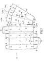
- Fig. 1 is a developed plan view of a blank according to the invention for obtaining a packaging case.
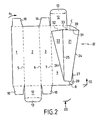
- Fig. 2 is a perspective showing certain operating phases of the constitution of the case from the blank according to FIG. 1.
- Fig. 3 is a transverse view of the case taken substantially along the plane III-III of FIG. 2.
- Fig. 1 shows a pre-cut blank, designated as a whole by the reference F and made from a suitable sheet of raw material such as compact cardboard or polypropylene.
- Fig. 1 represents the blank F seen by its so-called internal face, that is to say that which after shaping, will define the inside of the packaging case obtained.
- the cutting lines are shown in FIG. 1 in solid lines, while the fold lines are illustrated in long broken lines.
- the blank F of generally rectangular shape, has four panels 1 , 2 , 3 and 4, of generally rectangular shape, defined by four fold lines 5 , 6 , 7 and 8 which are marked parallel to each other.
- the panels 1 and 3 are called “intermediate”, while the panels 2 and 4 are called “main”.
- the panels 1 to 4 are arranged alternately, and, in the example shown, the panels 1 and 3 have the same width l 1 which is however less than the width L 1 also identical to the panels 2 and 4.
- the panels 1 to 4 are intended to allow, by folding along fold lines 5 , 6 , 7 and 8 , the constitution of an envelope of substantially parallelepipedic shape, whose open transverse ends can be closed by means of flaps. 12 provided with foldable tongues 13 and which extend, beyond folding lines 14 , at the end of the main panels 2 and 4 , for example.
- the closure of the transverse ends may also involve the presence of flaps 10 extending beyond fold lines 11 marking the transverse ends of the intermediate panels 1 and 3.
- the transverse fold lines 11 and 14 are marked in the same alignment substantially, being perpendicular to the lines 5 to 8 .
- the blank F is provided with an extension I which extends beyond the fold line 8 called, for this reason, "articulation".
- the extension I comprises a connecting strip 20 consisting of a trapezoidal portion 28 extending from the side of its small base into a tab 29 .
- This connecting strip 20 is also delimited at its transverse ends by an upper edge 30 in broken line and a lower edge 34 .
- first panel 21 articulated to the trapezoidal portion 28 of the connecting strip 20 , by a fold line 24 , and separated from the tab 29 , by a cutout 27 .
- This first panel 21 is also delimited at its transverse ends by an upper edge 31 and a lower edge 35 .
- the cutout 27 is parallel to the fold and articulation line 8 .
- the tab 29 is of rectangular shape.
- the first panel 21 is connected to a second panel 22 of triangular shape, by a fold line 25 .
- This second panel 22 is also delimited at the base of the triangle by an upper edge 32 .
- a third panel 23 extends from this second panel 22 , to which it is bound by a folding line 26 concurrent with the fold line 25 separating the first panel 21. from the second panel 22.
- This third panel 23 is also delimited at its transverse ends by an upper edge 33 and a lower edge 36 .
- the trapezoidal portion 28 of the connecting strip 20, the first panel 21, the second panel 22 and the third panel 23 all have a width of their transverse extent decreasing in the same direction.
- the fold lines 8 and 24 delimiting the trapezoidal portion of the connecting strip form an angle of value ⁇ substantially identical to that formed by the fold lines 25 and 26 delimiting the second panel 22 .
- the third panel 23 is defined by a fold line 26 and an extreme edge 40 forming an angle ⁇ of value substantially identical to that formed by the fold lines 24 and 25 delimiting the first panel 21.
- the first panel 21 , the second panel 22 and the third panel 23 of the extension (I) have lengths that are substantially identical or, preferably, less than the length L of the four panels 1 to 4 defining the perimeter envelope, which is measured in parallel at the connecting and connecting line 8.
- the width l 2 of the connecting strip 20, taken at the upper transverse edge 30 and the width 14 of the second panel 22 taken at the base of the triangle are substantially equal to or slightly smaller than the width l 1 of the intermediate panels 1 and 3.
- the width l 3 of the first panel 21, taken at the upper transverse edge 31 and the width, 15 of the third panel 23, taken at the upper transverse edge 33 are substantially equal to or slightly smaller than the width L 1 main panels 2 and 4.
- the shaping of the case according to the invention is carried out by successive bends along the fold lines 26, 25, 24 and 8, the extension I of the blank F in, respectively, the direction of the arrows f 1 , f 2 , f 3 and f 4 , so as to position the end edge 40 of the third panel 23 against the fold and hinge line 8 , to orient the connecting strip 20 substantially perpendicularly at the main panel 4 .
- the third panel 23 of the extension I is thus pressed against the main panel 4 adjacent to the connecting strip 20 and faces the first panel 21 .
- the conformation, as said above, of the extension I results in the formation of an internal cushioning structure II , which delimits a compartment C.
- an opening of the cutout 27 takes place at the same time as the conformation of the compartment C which is in the form of a pseudo-prism whose open base extends substantially in the plane or, preferably, set back from the corresponding transverse end of the future case.
- the presence of the second triangular panel 22 and the cutout 27 allow the panels 21 and 23 to meet at one of the transverse ends of the compartment C , called lower end.
- this lower end of the compartment C may be set back from the nearest transverse end of the perimeter envelope, said lower end.
- the present invention thus provides a case comprising an internal stall structure II defining a closed compartment C at its lower end.
- the unitary product to be packaged has, for example, a adapted conformation, similar to that of a tube whose cross section, corresponding to the bottom, is narrower than the cross-section corresponding to the access opening, for example closed by a removable cap, this product is stalled, and in case of fall, do not slide against the lower transverse end the perimeter envelope.
- the cross-sectional cross section of the C compartment decreasing and characterized by a decrease in the same direction of each of its sides, confers the compartment a shape that improves the lateral setting of the product to be packaged.
- This progressive narrowing of the transverse cross-section gives the compartment C an additional guiding and centering function when the introduction of the unitary product to be packaged, which is appreciable during a automatic machine packing.
- a subsequent phase of forming the holster then consists of marking the fold line 7, then the lines 6 and 5, so as to wind the corresponding panels 3, 2 and 1, in the direction of the arrow f 5 , to place the intermediate panel 3 parallel to the connecting strip 20, the main panel 2 parallel to the panel 4, and the intermediate panel 1 against the outer face of the connecting strip 20 , on which this panel is fixed, by any appropriate means such as that, for example, by gluing.
- the flap 20 opposite the shutter 22 of triangular shape, is secured to two adjacent sides 1 and 4 of the perimeter envelope.
- the upper edge 30 broken line of the connecting strip 20 and the tab 29 located on the side of the lower end of the compartment C allow gluing, along the entire length L of the panel 1 , thus conferring a better holding in the case, as well as better resistance to crushing.
- the four flaps 20 to 23 of the partition delimiting the internal blocking structure II all have a length less than the length L of the four panels 1 to 4 defining the perimeter envelope, measured parallel to the connecting line and 8 and the lower end of the compartment C is set back from the lower transverse end of the perimeter envelope.
- the upper edge 30 of the connecting strip 20 , the upper edge 31 of the first panel 21 , the upper edge 32 of the second panel 22 and the upper edge 33 of the third panel 23 are all four located in the extending from each other so that after formation of the case, the edges 31 , 32 and 33 are substantially at the same level, and set back from the upper transverse end of the perimeter envelope, as the shows more particularly FIG. 2.
Abstract
Description
La présente invention concerne le domaine technique du surconditionnement de produits préconditionnés qu'il convient de pouvoir emballer ou présenter, généralement à l'état unitaire, de manière à en faciliter la perception pour la clientèle, le stockage et la présentation sur des rayons ou gondoles d'offres à la vente.The present invention relates to the technical field of overpacking preconditioned products which must be able to be packed or presented, generally in the unitary state, so as to facilitate the perception of the customer, storage and presentation on shelves or gondolas of offers for sale.
Un tel domaine technique n'est pas nouveau en soi, et a fait l'objet d'un nombre assez important de propositions, en faisant intervenir des étuis de conditionnement obtenus par pliage d'un flan prédécoupé et rainé, le plus généralement réalisé à base d'une matière première appropriée et relativement bon marché, telle que le carton compact.Such a technical field is not new in itself, and has been the subject of a number of quite important proposals, involving packaging cases obtained by folding a pre-cut and grooved blank, the most commonly made based of a suitable raw material and relatively cheap, such as cardboard compact.
Les étuis utilisés présentent, généralement, une forme sensiblement parallélépipèdique qui, si elle est à même de contenir le produit à conditionner, n'est pas toujours satisfaisante dès lors que des fonctions supplémentaires sont à prendre en considération.The cases used generally have a form substantially parallelepiped which, if it is able to contain the product to be packaged, is not not always satisfactory when additional functions are to be taken in consideration.
Parmi ces fonctions, il convient de considérer une protection du produit unitaire préconditionné qu'il importe de préserver des risques de dégradation et d'écrasement, susceptibles de résulter, notamment, des manipulations de stockage, ainsi que des gerbages lors de la présentation.Among these functions, product protection should be considered preconditioned unit which it is important to preserve the risks of degradation and crushing, which may result, in particular, from storage manipulations, as well as stackings during the presentation.
Parmi ces fonctions, il convient aussi de prendre en compte la nécessité de pouvoir réaliser sur machines automatiques, d'une part, la constitution de l'étui de conditionnement à partir d'un flan pré-préparé, et, d'autre part, le garnissage en opération automatique d'un tel étui.Among these functions, account should also be taken of the need to can be realized on automatic machines, on the one hand, the constitution of the case of conditioning from a pre-prepared blank, and, on the other hand, the filling in automatic operation of such a case.
Dans certaines propositions de la technique antérieure, il a été évoqué la possibilité de conformer, à l'intérieur de l'étui de conditionnement, une sorte de compartiment interne censé répondre à la première fonction qui est celle de protection.In some proposals of the prior art, mention has been made of possibility of conforming, inside the packaging case, a kind of internal compartment supposed to meet the first function which is that of protection.
Le brevet US 3,050,231 propose, par exemple, un étui de conditionnement réalisé à partir d'un flan prédécoupé de carton compact. Cet étui de conditionnement est monté par pliage pour former une enveloppe périmétrique à panneaux articulés, destinée à constituer un corps d'étui sensiblement parallélépipèdique et comportant des volets et des rabats de fermeture des extrémités transversales du corps. L'étui comprend, également, une structure interne de calage formée par un prolongement rabattable et comportant une bande de liaison trapézoïdale, un premier panneau de largeur constante, un deuxième panneau de forme trapézoïdale convergeant dans le même sens que la bande de liaison, et un troisième panneau de largeur constante, délimités et articulés entre eux par des lignes de pliage orientées. Par ces moyens, la structure interne de calage délimite donc un compartiment interne dont les deux extrémités transversales sont ouvertes et situées dans les plans des fermetures transversales de l'étui.US Patent 3,050,231 proposes, for example, a packaging case made from a pre-cut blank of compact cardboard. This packaging case is foldably mounted to form a perimeter hoop with articulated panels, intended to constitute a substantially parallelepipedal case body and comprising flaps and closure flaps of the transverse ends of the body. The case also includes an internal cushioning structure formed by an extension foldable and having a trapezoidal connecting strip, a first panel of constant width, a second panel of trapezoidal shape converging in the same meaning as the connecting strip, and a third panel of constant width, delimited and articulated together by oriented folding lines. By these means, internal blocking structure thus delimits an internal compartment, the two of which transverse ends are open and located in the plans of the closures transverse of the case.
Or, il est apparu, à l'usage, qu'un tel étui ne garantissait pas toujours l'intégrité du produit conditionné. En effet, en cas de chute de l'étui, le produit a tendance à glisser dans le compartiment interne jusqu'à sortir par l'une des extrémités ouvertes et à venir s'écraser sur le fond du corps d'étui.However, it appeared, in use, that such a case did not always guarantee the integrity conditioned product. Indeed, in case of fall of the holster, the product tends to slide into the inner compartment until you exit through one of the open ends and to come crashing on the bottom of the case body.
Afin de remédier à cet inconvénient, il est donc apparu le besoin de disposer d'un étui de conditionnement, du type ci-dessus, qui présente une structure interne procurant un calage renforcé du produit à conditionner, et préservant, de ce fait, son intégrité.In order to remedy this disadvantage, the need for a packaging case, of the above type, which has an internal structure providing a reinforced wedging of the product to be conditioned, and thus preserving its integrity.
Un autre objectif de l'invention est de proposer un étui tenant compte de la forme particulière du produit unitaire préconditionné qui est surconditionné.Another object of the invention is to propose a case taking into account the particular form of the preconditioned unit product which is overpackaged.
Les étuis selon l'invention sont particulièrement adaptés pour le conditionnement d'un tube réalisé à partir d'une gaine en matière déformable et fermé par le fond, de sorte que le tube présente, au niveau de son embouchure, une forme sensiblement cylindrique qui va en s'aplatissant pour présenter une forme à l'extrémité opposée sensiblement prismatique, ou bien pour le conditionnement d'un sachet qui présente une extrémité plus épaisse que l'autre.The cases according to the invention are particularly suitable for conditioning a tube made from a sheath of deformable and closed material by the bottom, so that the tube has, at its mouth, a shape substantially cylindrical which goes flattening to present a shape to the opposite end substantially prismatic, or for the conditioning of a bag with one end thicker than the other.
Un autre objectif de l'invention est de proposer un nouvel étui de conditionnement qui présente des qualités renforcées de résistance à l'écrasement.Another object of the invention is to propose a new case of conditioning which has enhanced qualities of crush resistance.
La présente invention a également pour objectif de fournir un étui de conditionnement pour produit préconditionné qui offre la garantie de permettre une conformation et un garnissage de l'étui en machine automatique, sans risque de détérioration de l'étui, sans risque de dégradation du produit unitaire préconditionné et, le tout, à des cadences de production relativement élevées.The present invention also aims to provide a holster of packaging for preconditioned product which offers the guarantee of allowing a conformation and packing of the case in automatic machine, without risk of deterioration of the case, without risk of degradation of the preconditioned unit product and, all, at relatively high production rates.
Pour atteindre cet objectif, l'invention concerne un étui de conditionnement comprenant :
- une enveloppe périmétrique à quatre côtés, dont les extrémités transversales sont munies de volets et de rabats de fermeture repliables; et
- une structure de calage, solidaire de l'enveloppe périmétrique et interne à celle-ci, et délimitée par une cloison à quatre panneaux, pliée et contrepliée, formant un compartiment de section droite transversale décroissante,
- a four-sided perimeter envelope, the transverse ends of which are provided with flaps and foldable closure flaps; and
- a wedging structure integral with the perimeter casing and internal to the latter, and delimited by a partition with four panels, folded and pleated, forming a compartment of decreasing cross section,
L'invention vise également, pour la constitution de l'étui, un flan prédécoupé comprenant au moins quatre panneaux disposés parallèlement, délimités par des lignes de pliage, pourvus, pour certains d'entre eux au moins, de rabats, et définissant une fois pliés une enveloppe périmétrique dont les extrémités transversales ouvertes peuvent être fermées par lesdits rabats, l'un des panneaux extrêmes étant pourvu d'un prolongement définissant, après pliage, une structure de calage interne à l'enveloppe, ledit prolongement comprenant :
- une bande de liaison, s'étendant le long du panneau extrême auquel elle est liée par une ligne de pliage et d'articulation,
- et à partir de ladite bande :
- un premier panneau,
- un deuxième panneau, lié au premier panneau par une ligne de pliage,
- un troisième panneau, lié au deuxième panneau par une ligne de pliage,
- la bande de liaison est constituée d'une partie trapézoïdale liée au premier panneau par une ligne de pliage et d'une patte située dans le prolongement de la petite base de la partie trapézoïdale et séparée du premier panneau par une découpe,
- le deuxième panneau est de forme triangulaire,
- la partie trapézoïdale de la bande de liaison, le premier panneau, le deuxième panneau et le troisième panneau présentent tous une largeur de leur étendue transversale décroissant dans le même sens.
- a connecting strip, extending along the end panel to which it is bound by a fold and articulation line,
- and from said band:
- a first panel,
- a second panel, linked to the first panel by a fold line,
- a third panel, linked to the second panel by a fold line,
- the connecting strip consists of a trapezoidal part connected to the first panel by a fold line and a tab located in the extension of the small base of the trapezoidal part and separated from the first panel by a cutout,
- the second panel is triangular in shape,
- the trapezoidal portion of the connecting strip, the first panel, the second panel and the third panel all have a width of their transverse extent decreasing in the same direction.
Diverses autres caractéristiques ressortent de la description faite ci-dessous, en référence aux dessins annexés qui montrent, à titre d'exemples non limitatifs, des formes de réalisation de l'objet de l'invention.Various other features emerge from the description given below, in reference to the accompanying drawings which show, by way of non-limiting examples, embodiments of the subject of the invention.
La fig. 1 est une vue en plan développé d'un flan conforme à l'invention pour l'obtention d'un étui de conditionnement. Fig. 1 is a developed plan view of a blank according to the invention for obtaining a packaging case.
La fig. 2 est une perspective mettant en évidence certaines phases opératoires de la constitution de l'étui à partir du flan selon la fig. 1. Fig. 2 is a perspective showing certain operating phases of the constitution of the case from the blank according to FIG. 1.
La fig. 3 est une vue transversale de l'étui prise sensiblement selon le plan III-III de la fig. 2. Fig. 3 is a transverse view of the case taken substantially along the plane III-III of FIG. 2.
La fig. 1 représente un flan prédécoupé, désigné dans son ensemble par la référence F et réalisé à partir d'une feuille de matière première appropriée telle que du carton compact ou encore du polypropylène. Fig. 1 shows a pre-cut blank, designated as a whole by the reference F and made from a suitable sheet of raw material such as compact cardboard or polypropylene.
La fig. 1 représente le flan F vu par sa face dite interne, c'est-à-dire celle qui après conformation, définira l'intérieur de l'étui de conditionnement obtenu. Les lignes de coupe sont représentées à la fig. 1 en traits pleins, tandis que les lignes de pliage sont illustrées en traits interrompus longs. Fig. 1 represents the blank F seen by its so-called internal face, that is to say that which after shaping, will define the inside of the packaging case obtained. The cutting lines are shown in FIG. 1 in solid lines, while the fold lines are illustrated in long broken lines.
Le flan F, de forme générale rectangulaire, possède quatre panneaux 1, 2, 3 et
4, de forme générale rectangulaire, définis par quatre lignes de pliage 5, 6, 7 et 8 qui
sont marquées parallèlement entre elles. Les panneaux 1 et 3 sont dénommés
"intermédiaires", alors que les panneaux 2 et 4 sont dénommés "principaux". Les
panneaux 1 à 4 sont disposés de façon alternée, et, dans l'exemple illustré, les
panneaux 1 et 3 présentent une même largeur l1 qui est toutefois inférieure à la
largeur L1 également identique des panneaux 2 et 4. The blank F , of generally rectangular shape, has four
Les panneaux 1 à 4 sont destinés à permettre, par pliage selon des lignes de
pliage 5, 6, 7 et 8, la constitution d'une enveloppe de forme sensiblement
parallélépipèdique, dont les extrémités transversales ouvertes peuvent être fermées
par l'intermédiaire de rabats 12 pourvus de languettes repliables 13 et qui s'étendent,
au-delà de lignes de pliage 14, en bout des panneaux principaux 2 et 4, par exemple.
La fermeture des extrémités transversales peut aussi faire intervenir la présence de
volets 10 s'étendant au-delà de lignes de pliage 11 marquant les extrémités
transversales des panneaux intermédiaires 1 et 3. Comme cela ressort de la fig. 1, les
lignes de pliage transversales 11 et 14 sont marquées dans le même alignement
sensiblement, en étant perpendiculaires aux lignes 5 à 8. The
Selon l'invention, le flan F est pourvu d'un prolongement I qui s'étend au-delà
de la ligne de pliage 8 dite, pour cette raison, "d'articulation".According to the invention, the blank F is provided with an extension I which extends beyond the
Le prolongement I comprend une bande de liaison 20 constituée d'une partie
trapézoïdale 28 se prolongeant du côté de sa petite base en une patte 29. Cette bande
de liaison 20 est également délimitée à ses extrémités transversales par un bord
supérieur 30 en ligne brisée et un bord inférieur 34.The extension I comprises a connecting
Au delà de cette bande de liaison 20, s'étend un premier panneau 21, articulé à
la partie trapézoïdale 28 de la bande liaison 20, par une ligne de pliage 24, et séparé
de la patte 29, par une découpe 27. Ce premier panneau 21 est également délimité à
ses extrémités transversales par un bord supérieur 31 et un bord inférieur 35.Beyond this connecting
Selon la variante représentée à la fig. 1, la découpe 27 est parallèle à la ligne de
pliage et d'articulation 8. La patte 29 est donc de forme rectangulaire.According to the variant shown in FIG. 1, the
Le premier panneau 21 est lié à un deuxième panneau 22 de forme triangulaire,
par une ligne de pliage 25. Ce deuxième panneau 22 est également délimité à la base
du triangle par un bord supérieur 32.The
Un troisième panneau 23 s'étend à partir de ce deuxième panneau 22, auquel il
est lié par une ligne de pliage 26 concourante avec la ligne de pliage 25 séparant le
premier panneau 21. du deuxième panneau 22. Ce troisième panneau 23 est
également délimité à ses extrémités transversales par un bord supérieur 33 et un bord
inférieur 36.A
La partie trapézoïdale 28 de la bande de liaison 20, le premier panneau 21, le
deuxième panneau 22 et le troisième panneau 23 présentent, tous, une largeur de leur
étendue transversale décroissant dans le même sens.The
Il ressort également de la fig. 1 que, selon un mode de réalisation préféré, les
lignes de pliage 8 et 24 délimitant la partie trapézoïdale de la bande de liaison
forment un angle de valeur α sensiblement identique à celui formé par les lignes de
pliages 25 et 26 délimitant le deuxième panneau 22. Par ailleurs, le troisième
panneau 23 est délimité par une ligne de pliage 26 et un bord extrême 40 formant un
angle de valeur β sensiblement identique à celui formé par les lignes de pliage 24 et
25 délimitant le premier panneau 21.It is also apparent from FIG. 1 that, according to a preferred embodiment, the
Le premier panneau 21, le deuxième panneau 22 et le troisième panneau 23 du
prolongement (I) possèdent des longueurs sensiblement identiques ou, de préférence,
inférieures à la longueur L des quatre panneaux 1 à 4 définissant l'enveloppe
périmétrique, laquelle est mesurée parallèlement à la ligne de liaison et
d'articulation 8. The
La largeur l2 de la bande de liaison 20, prise au bord transversal supérieur 30 et
la largeur, l4 du deuxième panneau 22 prise à la base du triangle sont sensiblement
égales, voire légèrement inférieures à la largeur l1 des panneaux intermédiaires 1 et 3.
De même, la largeur l3 du premier panneau 21, prise au bord transversal supérieur 31
et la largeur, l5 du troisième panneau 23, prise au bord transversal supérieur 33, sont
sensiblement égales, voire légèrement inférieures à la largeur L1 des panneaux
principaux 2 et 4. The width l 2 of the connecting
A partir du flan décrit ci-dessus, la constitution d'un étui conforme à l'invention s'opère de la façon suivante.From the blank described above, the constitution of a holster according to the invention operates as follows.
La mise en forme de l'étui selon l'invention, à partir du flan F, s'effectue par
pliages successifs le long des lignes de pliage 26, 25, 24 et 8, du prolongement I du
flan F dans, respectivement, le sens des flèches f1, f2, f3 et f4, de manière à venir
positionner le bord extrême 40 du troisième panneau 23 contre la ligne de pliage et
d'articulation 8, pour orienter la bande de liaison 20 de façon sensiblement
perpendiculaire au panneau principal 4. Le troisième panneau 23 du prolongement I
se trouve ainsi plaqué contre le panneau principal 4 adjacent à la bande de liaison 20
et fait face au premier panneau 21.The shaping of the case according to the invention, starting from the blank F , is carried out by successive bends along the fold lines 26, 25, 24 and 8, the extension I of the blank F in, respectively, the direction of the arrows f 1 , f 2 , f 3 and f 4 , so as to position the end edge 40 of the
Comme cela ressort de la fig. 2, la conformation, comme dit ci-dessus, du
prolongement I, aboutit à la formation d'une structure interne de calage II, qui
délimite un compartiment C. Par la conformation triangulaire du deuxième panneau
22, une ouverture de la découpe 27 s'opère en même temps que la conformation du
compartiment C qui se présente sous la forme d'un pseudo-prisme dont la base
ouverte s'étend sensiblement dans le plan ou, de préférence, en retrait de l'extrémité
transversale correspondante de l'étui futur.As is apparent from FIG. 2, the conformation, as said above, of the extension I , results in the formation of an internal cushioning structure II , which delimits a compartment C. By the triangular conformation of the
Ainsi, comme cela apparaít sur la fig. 3, la présence du deuxième panneau
triangulaire 22 et de la découpe 27 permettent aux panneaux 21 et 23 de se rejoindre
à l'une des extrémités transversales du compartiment C, dénommée extrémité
inférieure. Comme cela ressort de la fig. 2, cette extrémité inférieure du
compartiment C peut être située en retrait par rapport à l'extrémité transversale la
plus proche de l'enveloppe périmétrique, dite extrémité inférieure. Thus, as shown in FIG. 3, the presence of the second
A la différence de l'art antérieur, la présente invention fournit donc un étui comprenant une structure de calage interne II définissant un compartiment C fermé à son extrémité inférieure.Unlike the prior art, the present invention thus provides a case comprising an internal stall structure II defining a closed compartment C at its lower end.
Ainsi, lorsque le produit unitaire à conditionner présente, par exemple, une conformation adaptée, analogue à celle d'un tube dont la section droite, correspondant au fond, est moins large que la section droite correspondant à l'ouverture d'accès, par exemple obturée par un bouchon amovible, ce produit se trouve calé, et en cas de chute, ne glisse pas contre l'extrémité transversale inférieure de l'enveloppe périmétrique.Thus, when the unitary product to be packaged has, for example, a adapted conformation, similar to that of a tube whose cross section, corresponding to the bottom, is narrower than the cross-section corresponding to the access opening, for example closed by a removable cap, this product is stalled, and in case of fall, do not slide against the lower transverse end the perimeter envelope.
De plus, la section droite transversale du compartiment C décroissante et caractérisée par une décroissance dans le même sens de chacun de ses côtés, confère au compartiment une forme qui améliore le calage latéral du produit à conditionner. Ce rétrécissement progressif de la section droite transversale confère au compartiment C une fonction supplémentaire de guidage et de centrage lors de l'introduction du produit unitaire à conditionner, appréciable lors d'une opération de garnissage par machine automatique.In addition, the cross-sectional cross section of the C compartment decreasing and characterized by a decrease in the same direction of each of its sides, confers the compartment a shape that improves the lateral setting of the product to be packaged. This progressive narrowing of the transverse cross-section gives the compartment C an additional guiding and centering function when the introduction of the unitary product to be packaged, which is appreciable during a automatic machine packing.
Une phase ultérieure de formation de l'étui consiste ensuite à marquer la ligne
de pliage 7, puis les lignes 6 et 5, de manière à enrouler les panneaux correspondants
3, 2 et 1, dans le sens de la flèche f5, pour placer le panneau intermédiaire 3
parallèlement à la bande de liaison 20, le panneau principal 2 parallèlement au
panneau 4, et le panneau intermédiaire 1 contre la face extérieure de la bande de
liaison 20, sur laquelle ce panneau est fixé, par tout moyen approprié, tel que, par
exemple, par collage.A subsequent phase of forming the holster then consists of marking the
Ainsi, le volet 20, opposé au volet 22 de forme triangulaire, est solidaire de
deux côtés adjacents 1 et 4 de l'enveloppe périmétrique. De plus, le bord supérieur 30
en ligne brisée de la bande de liaison 20 et la patte 29 située du côté de l'extrémité
inférieure du compartiment C, autorisent un collage, sur toute la longueur L du
panneau 1, conférant ainsi une meilleure tenue à l'étui, ainsi qu'une meilleure
résistance à l'écrasement.Thus, the
Selon le mode de réalisation illustré à la fig. 2, les quatre volets 20 à 23 de la
cloison délimitant la structure interne de calage II possèdent, tous, une longueur
inférieure à la longueur L des quatre panneaux 1 à 4 définissant l'enveloppe
périmétrique, mesurée parallèlement à la ligne de liaison et d'articulation 8 et
l'extrémité inférieure du compartiment C est située en retrait par rapport à
l'extrémité transversale inférieure de l'enveloppe périmétrique.According to the embodiment illustrated in FIG. 2, the four
Dans l'exemple représenté à la fig. 1, il apparaít également que le bord
supérieur 30 de la bande de liaison 20, le bord supérieur 31 du premier panneau 21,
le bord supérieur 32 du deuxième panneau 22 et le bord supérieur 33 du troisième
panneau 23 sont tous les quatre situés dans le prolongement les uns des autres de
sorte, qu'après formation de l'étui, les bords 31, 32 et 33 se trouvent sensiblement au
même niveau, et en retrait par rapport à l'extrémité transversale supérieure de
l'enveloppe périmétrique, comme le montre plus particulièrement la fig. 2. In the example shown in FIG. 1 , it also appears that the
Claims (9)
Applications Claiming Priority (2)
| Application Number | Priority Date | Filing Date | Title |
|---|---|---|---|
| FR0111498 | 2001-09-05 | ||
| FR0111498A FR2829109B1 (en) | 2001-09-05 | 2001-09-05 | PACKAGING CASE AND BLANK FOR ITS CONSTITUTION |
Publications (2)
| Publication Number | Publication Date |
|---|---|
| EP1291285A1 true EP1291285A1 (en) | 2003-03-12 |
| EP1291285B1 EP1291285B1 (en) | 2006-03-29 |
Family
ID=8867000
Family Applications (1)
| Application Number | Title | Priority Date | Filing Date |
|---|---|---|---|
| EP02356170A Expired - Lifetime EP1291285B1 (en) | 2001-09-05 | 2002-09-02 | Packaging case and blank for forming the same |
Country Status (5)
| Country | Link |
|---|---|
| EP (1) | EP1291285B1 (en) |
| AT (1) | ATE321702T1 (en) |
| DE (1) | DE60210241T2 (en) |
| ES (1) | ES2261617T3 (en) |
| FR (1) | FR2829109B1 (en) |
Citations (2)
| Publication number | Priority date | Publication date | Assignee | Title |
|---|---|---|---|---|
| US3050231A (en) | 1959-08-18 | 1962-08-21 | Standard Packaging Corp | Protective carton |
| EP1095866A1 (en) * | 1999-10-29 | 2001-05-02 | Finega | Box provided with wedge-like compartments |
-
2001
- 2001-09-05 FR FR0111498A patent/FR2829109B1/en not_active Expired - Fee Related
-
2002
- 2002-09-02 EP EP02356170A patent/EP1291285B1/en not_active Expired - Lifetime
- 2002-09-02 AT AT02356170T patent/ATE321702T1/en not_active IP Right Cessation
- 2002-09-02 DE DE60210241T patent/DE60210241T2/en not_active Expired - Lifetime
- 2002-09-02 ES ES02356170T patent/ES2261617T3/en not_active Expired - Lifetime
Patent Citations (2)
| Publication number | Priority date | Publication date | Assignee | Title |
|---|---|---|---|---|
| US3050231A (en) | 1959-08-18 | 1962-08-21 | Standard Packaging Corp | Protective carton |
| EP1095866A1 (en) * | 1999-10-29 | 2001-05-02 | Finega | Box provided with wedge-like compartments |
Also Published As
| Publication number | Publication date |
|---|---|
| ES2261617T3 (en) | 2006-11-16 |
| FR2829109A1 (en) | 2003-03-07 |
| DE60210241T2 (en) | 2007-01-11 |
| EP1291285B1 (en) | 2006-03-29 |
| ATE321702T1 (en) | 2006-04-15 |
| FR2829109B1 (en) | 2003-12-12 |
| DE60210241D1 (en) | 2006-05-18 |
Similar Documents
| Publication | Publication Date | Title |
|---|---|---|
| CA2274719A1 (en) | Wrapping-type packaging with an integrated lateral carrying handle | |
| CA2353317C (en) | Box made of cardboard or similar material with improved closure device | |
| EP0919481B1 (en) | Packaging box with a securing device | |
| EP2436607B1 (en) | Pre-cut blank for making a distribution packaging element comprising two sliding elements inserted in one another | |
| EP0904235A1 (en) | Blank for producing a package with nesting lid | |
| FR2915181A1 (en) | Packaging case for e.g. tube, has adjusting internal structure with connecting strip folded back against panel, and adjusting panel conformed for extending freely in projection with respect to panel | |
| EP0114772B1 (en) | Blank for making a package provided with a handle, and corresponding preformed package and package | |
| EP1291285B1 (en) | Packaging case and blank for forming the same | |
| EP1186540B1 (en) | Carton with wedge-shaped compartments | |
| FR2931803A1 (en) | Carrying case for packaging and protection of e.g. bottles, has separating shutters cut into set of lateral panels of envelope to push back towards interior of envelope for delimiting compartments to receive products to be packaged | |
| EP1095866B1 (en) | Box provided with wedge-like compartments | |
| CH693591A5 (en) | Folding box for bakery or pastry products. | |
| FR2653747A1 (en) | Package with strap forming a handle, made from cardboard, corrugated cardboard or other sheet material suitably cut out and folded, and corresponding blank | |
| FR2864825A1 (en) | Packaging case for unitary product e.g. cosmetic tube, has one main panel with window for display of contents of case, and internal wedging structure to define cell having U shaped transversal cross-section and opening towards window | |
| FR2615823A1 (en) | Cardboard packaging box | |
| FR2634456A1 (en) | Package with a handle and blank capable of making such a package | |
| EP1195330B1 (en) | Packaging case for at least one unitary product and blank for forming the same | |
| BE1011772A3 (en) | Holder | |
| FR3005037A1 (en) | FLAN PREDECOUPE AND PACKAGING CASE THUS OBTAINED, ESPECIALLY FOR SYRINGE | |
| EP0929449A1 (en) | Pack provided with flexible internal envelope and method of its manufacture | |
| EP1553024B1 (en) | Divisible package for foodstuffs | |
| FR2639917A1 (en) | Parallelepipedal package having a closable lid, blank suitable for forming such a package, and corresponding packaging preform | |
| EP2913275B1 (en) | Pre-cut blank for manufacturing a box with a built-in pour spout | |
| FR2902084A1 (en) | Product e.g. perfume, packaging and protecting case, has tubular envelope including four articulated lateral panels and opened at top and bottom ends, and closing unit closing bottom end and placed at specific distance from support plane | |
| FR2537548A1 (en) | Cut-out blank for forming a box with an automatic bottom and a separate lid and its method of folding and pasting |
Legal Events
| Date | Code | Title | Description |
|---|---|---|---|
| PUAI | Public reference made under article 153(3) epc to a published international application that has entered the european phase |
Free format text: ORIGINAL CODE: 0009012 |
|
| AK | Designated contracting states |
Kind code of ref document: A1 Designated state(s): AT BE BG CH CY CZ DE DK EE ES FI FR GB GR IE IT LI LU MC NL PT SE SK TR Designated state(s): AT BE BG CH CY CZ DE DK EE ES FI FR GB GR IE IT LI LU MC NL PT SE SK TR |
|
| AX | Request for extension of the european patent |
Extension state: AL LT LV MK RO SI |
|
| 17P | Request for examination filed |
Effective date: 20030804 |
|
| AKX | Designation fees paid |
Designated state(s): AT BE BG CH CY CZ DE DK EE ES FI FR GB GR IE IT LI LU MC NL PT SE SK TR |
|
| GRAP | Despatch of communication of intention to grant a patent |
Free format text: ORIGINAL CODE: EPIDOSNIGR1 |
|
| GRAS | Grant fee paid |
Free format text: ORIGINAL CODE: EPIDOSNIGR3 |
|
| GRAA | (expected) grant |
Free format text: ORIGINAL CODE: 0009210 |
|
| AK | Designated contracting states |
Kind code of ref document: B1 Designated state(s): AT BE BG CH CY CZ DE DK EE ES FI FR GB GR IE IT LI LU MC NL PT SE SK TR |
|
| PG25 | Lapsed in a contracting state [announced via postgrant information from national office to epo] |
Ref country code: AT Free format text: LAPSE BECAUSE OF FAILURE TO SUBMIT A TRANSLATION OF THE DESCRIPTION OR TO PAY THE FEE WITHIN THE PRESCRIBED TIME-LIMIT Effective date: 20060329 Ref country code: SK Free format text: LAPSE BECAUSE OF FAILURE TO SUBMIT A TRANSLATION OF THE DESCRIPTION OR TO PAY THE FEE WITHIN THE PRESCRIBED TIME-LIMIT Effective date: 20060329 Ref country code: NL Free format text: LAPSE BECAUSE OF FAILURE TO SUBMIT A TRANSLATION OF THE DESCRIPTION OR TO PAY THE FEE WITHIN THE PRESCRIBED TIME-LIMIT Effective date: 20060329 Ref country code: IE Free format text: LAPSE BECAUSE OF FAILURE TO SUBMIT A TRANSLATION OF THE DESCRIPTION OR TO PAY THE FEE WITHIN THE PRESCRIBED TIME-LIMIT Effective date: 20060329 |
|
| REG | Reference to a national code |
Ref country code: GB Ref legal event code: FG4D Free format text: NOT ENGLISH |
|
| REG | Reference to a national code |
Ref country code: CH Ref legal event code: EP |
|
| REG | Reference to a national code |
Ref country code: IE Ref legal event code: FG4D Free format text: LANGUAGE OF EP DOCUMENT: FRENCH |
|
| REF | Corresponds to: |
Ref document number: 60210241 Country of ref document: DE Date of ref document: 20060518 Kind code of ref document: P |
|
| PG25 | Lapsed in a contracting state [announced via postgrant information from national office to epo] |
Ref country code: DK Free format text: LAPSE BECAUSE OF FAILURE TO SUBMIT A TRANSLATION OF THE DESCRIPTION OR TO PAY THE FEE WITHIN THE PRESCRIBED TIME-LIMIT Effective date: 20060629 Ref country code: SE Free format text: LAPSE BECAUSE OF FAILURE TO SUBMIT A TRANSLATION OF THE DESCRIPTION OR TO PAY THE FEE WITHIN THE PRESCRIBED TIME-LIMIT Effective date: 20060629 Ref country code: BG Free format text: LAPSE BECAUSE OF FAILURE TO SUBMIT A TRANSLATION OF THE DESCRIPTION OR TO PAY THE FEE WITHIN THE PRESCRIBED TIME-LIMIT Effective date: 20060629 |
|
| GBT | Gb: translation of ep patent filed (gb section 77(6)(a)/1977) |
Effective date: 20060626 |
|
| REG | Reference to a national code |
Ref country code: CH Ref legal event code: NV Representative=s name: BOVARD AG PATENTANWAELTE |
|
| PG25 | Lapsed in a contracting state [announced via postgrant information from national office to epo] |
Ref country code: PT Free format text: LAPSE BECAUSE OF FAILURE TO SUBMIT A TRANSLATION OF THE DESCRIPTION OR TO PAY THE FEE WITHIN THE PRESCRIBED TIME-LIMIT Effective date: 20060829 |
|
| PG25 | Lapsed in a contracting state [announced via postgrant information from national office to epo] |
Ref country code: MC Free format text: LAPSE BECAUSE OF NON-PAYMENT OF DUE FEES Effective date: 20060930 |
|
| NLV1 | Nl: lapsed or annulled due to failure to fulfill the requirements of art. 29p and 29m of the patents act | ||
| REG | Reference to a national code |
Ref country code: IE Ref legal event code: FD4D |
|
| REG | Reference to a national code |
Ref country code: ES Ref legal event code: FG2A Ref document number: 2261617 Country of ref document: ES Kind code of ref document: T3 |
|
| PLBE | No opposition filed within time limit |
Free format text: ORIGINAL CODE: 0009261 |
|
| STAA | Information on the status of an ep patent application or granted ep patent |
Free format text: STATUS: NO OPPOSITION FILED WITHIN TIME LIMIT |
|
| 26N | No opposition filed |
Effective date: 20070102 |
|
| PG25 | Lapsed in a contracting state [announced via postgrant information from national office to epo] |
Ref country code: CZ Free format text: LAPSE BECAUSE OF FAILURE TO SUBMIT A TRANSLATION OF THE DESCRIPTION OR TO PAY THE FEE WITHIN THE PRESCRIBED TIME-LIMIT Effective date: 20060329 Ref country code: GR Free format text: LAPSE BECAUSE OF FAILURE TO SUBMIT A TRANSLATION OF THE DESCRIPTION OR TO PAY THE FEE WITHIN THE PRESCRIBED TIME-LIMIT Effective date: 20060630 |
|
| PG25 | Lapsed in a contracting state [announced via postgrant information from national office to epo] |
Ref country code: FI Free format text: LAPSE BECAUSE OF FAILURE TO SUBMIT A TRANSLATION OF THE DESCRIPTION OR TO PAY THE FEE WITHIN THE PRESCRIBED TIME-LIMIT Effective date: 20060329 Ref country code: EE Free format text: LAPSE BECAUSE OF FAILURE TO SUBMIT A TRANSLATION OF THE DESCRIPTION OR TO PAY THE FEE WITHIN THE PRESCRIBED TIME-LIMIT Effective date: 20060329 |
|
| PG25 | Lapsed in a contracting state [announced via postgrant information from national office to epo] |
Ref country code: LU Free format text: LAPSE BECAUSE OF NON-PAYMENT OF DUE FEES Effective date: 20060902 Ref country code: TR Free format text: LAPSE BECAUSE OF FAILURE TO SUBMIT A TRANSLATION OF THE DESCRIPTION OR TO PAY THE FEE WITHIN THE PRESCRIBED TIME-LIMIT Effective date: 20060329 |
|
| PG25 | Lapsed in a contracting state [announced via postgrant information from national office to epo] |
Ref country code: CY Free format text: LAPSE BECAUSE OF FAILURE TO SUBMIT A TRANSLATION OF THE DESCRIPTION OR TO PAY THE FEE WITHIN THE PRESCRIBED TIME-LIMIT Effective date: 20060329 |
|
| REG | Reference to a national code |
Ref country code: CH Ref legal event code: PFA Owner name: FINEGA Free format text: FINEGA#ZONE INDUSTRIELLE DE GOURNIER, ROUTE DE CHATEAUNEUF#26200 MONTELIMAR (FR) -TRANSFER TO- FINEGA#ZONE INDUSTRIELLE DE GOURNIER, ROUTE DE CHATEAUNEUF#26200 MONTELIMAR (FR) |
|
| PGFP | Annual fee paid to national office [announced via postgrant information from national office to epo] |
Ref country code: DE Payment date: 20140911 Year of fee payment: 13 Ref country code: CH Payment date: 20140915 Year of fee payment: 13 |
|
| PGFP | Annual fee paid to national office [announced via postgrant information from national office to epo] |
Ref country code: ES Payment date: 20140919 Year of fee payment: 13 Ref country code: GB Payment date: 20140917 Year of fee payment: 13 |
|
| PGFP | Annual fee paid to national office [announced via postgrant information from national office to epo] |
Ref country code: IT Payment date: 20140915 Year of fee payment: 13 |
|
| PGFP | Annual fee paid to national office [announced via postgrant information from national office to epo] |
Ref country code: BE Payment date: 20140929 Year of fee payment: 13 |
|
| REG | Reference to a national code |
Ref country code: DE Ref legal event code: R119 Ref document number: 60210241 Country of ref document: DE |
|
| PG25 | Lapsed in a contracting state [announced via postgrant information from national office to epo] |
Ref country code: IT Free format text: LAPSE BECAUSE OF NON-PAYMENT OF DUE FEES Effective date: 20150902 |
|
| REG | Reference to a national code |
Ref country code: CH Ref legal event code: PL |
|
| GBPC | Gb: european patent ceased through non-payment of renewal fee |
Effective date: 20150902 |
|
| PG25 | Lapsed in a contracting state [announced via postgrant information from national office to epo] |
Ref country code: CH Free format text: LAPSE BECAUSE OF NON-PAYMENT OF DUE FEES Effective date: 20150930 Ref country code: LI Free format text: LAPSE BECAUSE OF NON-PAYMENT OF DUE FEES Effective date: 20150930 Ref country code: DE Free format text: LAPSE BECAUSE OF NON-PAYMENT OF DUE FEES Effective date: 20160401 Ref country code: GB Free format text: LAPSE BECAUSE OF NON-PAYMENT OF DUE FEES Effective date: 20150902 |
|
| REG | Reference to a national code |
Ref country code: FR Ref legal event code: PLFP Year of fee payment: 15 |
|
| REG | Reference to a national code |
Ref country code: ES Ref legal event code: FD2A Effective date: 20161026 |
|
| PG25 | Lapsed in a contracting state [announced via postgrant information from national office to epo] |
Ref country code: ES Free format text: LAPSE BECAUSE OF NON-PAYMENT OF DUE FEES Effective date: 20150903 |
|
| PG25 | Lapsed in a contracting state [announced via postgrant information from national office to epo] |
Ref country code: BE Free format text: LAPSE BECAUSE OF NON-PAYMENT OF DUE FEES Effective date: 20150930 |
|
| REG | Reference to a national code |
Ref country code: FR Ref legal event code: PLFP Year of fee payment: 16 |
|
| REG | Reference to a national code |
Ref country code: FR Ref legal event code: PLFP Year of fee payment: 17 |
|
| PGFP | Annual fee paid to national office [announced via postgrant information from national office to epo] |
Ref country code: FR Payment date: 20210831 Year of fee payment: 20 |