EP1291237B1 - Kraftfahrzeug-Sitzstruktur mit einem Gehäuse - Google Patents
Kraftfahrzeug-Sitzstruktur mit einem Gehäuse Download PDFInfo
- Publication number
- EP1291237B1 EP1291237B1 EP20020292008 EP02292008A EP1291237B1 EP 1291237 B1 EP1291237 B1 EP 1291237B1 EP 20020292008 EP20020292008 EP 20020292008 EP 02292008 A EP02292008 A EP 02292008A EP 1291237 B1 EP1291237 B1 EP 1291237B1
- Authority
- EP
- European Patent Office
- Prior art keywords
- box
- groove
- finger
- pin
- housing
- Prior art date
- Legal status (The legal status is an assumption and is not a legal conclusion. Google has not performed a legal analysis and makes no representation as to the accuracy of the status listed.)
- Expired - Lifetime
Links
- 238000006073 displacement reaction Methods 0.000 claims description 11
- 230000000694 effects Effects 0.000 claims description 2
- 210000004197 pelvis Anatomy 0.000 description 3
- 230000035939 shock Effects 0.000 description 2
- 238000005452 bending Methods 0.000 description 1
- 238000010304 firing Methods 0.000 description 1
- 210000000056 organ Anatomy 0.000 description 1
- 230000000750 progressive effect Effects 0.000 description 1
- 230000000284 resting effect Effects 0.000 description 1
- 230000002441 reversible effect Effects 0.000 description 1
Images

Classifications
-
- B—PERFORMING OPERATIONS; TRANSPORTING
- B60—VEHICLES IN GENERAL
- B60N—SEATS SPECIALLY ADAPTED FOR VEHICLES; VEHICLE PASSENGER ACCOMMODATION NOT OTHERWISE PROVIDED FOR
- B60N2/00—Seats specially adapted for vehicles; Arrangement or mounting of seats in vehicles
- B60N2/24—Seats specially adapted for vehicles; Arrangement or mounting of seats in vehicles for particular purposes or particular vehicles
- B60N2/42—Seats specially adapted for vehicles; Arrangement or mounting of seats in vehicles for particular purposes or particular vehicles the seat constructed to protect the occupant from the effect of abnormal g-forces, e.g. crash or safety seats
- B60N2/4207—Seats specially adapted for vehicles; Arrangement or mounting of seats in vehicles for particular purposes or particular vehicles the seat constructed to protect the occupant from the effect of abnormal g-forces, e.g. crash or safety seats characterised by the direction of the g-forces
- B60N2/4214—Seats specially adapted for vehicles; Arrangement or mounting of seats in vehicles for particular purposes or particular vehicles the seat constructed to protect the occupant from the effect of abnormal g-forces, e.g. crash or safety seats characterised by the direction of the g-forces longitudinal
- B60N2/4221—Seats specially adapted for vehicles; Arrangement or mounting of seats in vehicles for particular purposes or particular vehicles the seat constructed to protect the occupant from the effect of abnormal g-forces, e.g. crash or safety seats characterised by the direction of the g-forces longitudinal due to impact coming from the front
-
- B—PERFORMING OPERATIONS; TRANSPORTING
- B60—VEHICLES IN GENERAL
- B60N—SEATS SPECIALLY ADAPTED FOR VEHICLES; VEHICLE PASSENGER ACCOMMODATION NOT OTHERWISE PROVIDED FOR
- B60N2/00—Seats specially adapted for vehicles; Arrangement or mounting of seats in vehicles
- B60N2/24—Seats specially adapted for vehicles; Arrangement or mounting of seats in vehicles for particular purposes or particular vehicles
- B60N2/42—Seats specially adapted for vehicles; Arrangement or mounting of seats in vehicles for particular purposes or particular vehicles the seat constructed to protect the occupant from the effect of abnormal g-forces, e.g. crash or safety seats
- B60N2/427—Seats or parts thereof displaced during a crash
- B60N2/42709—Seats or parts thereof displaced during a crash involving residual deformation or fracture of the structure
-
- B—PERFORMING OPERATIONS; TRANSPORTING
- B60—VEHICLES IN GENERAL
- B60N—SEATS SPECIALLY ADAPTED FOR VEHICLES; VEHICLE PASSENGER ACCOMMODATION NOT OTHERWISE PROVIDED FOR
- B60N2/00—Seats specially adapted for vehicles; Arrangement or mounting of seats in vehicles
- B60N2/24—Seats specially adapted for vehicles; Arrangement or mounting of seats in vehicles for particular purposes or particular vehicles
- B60N2/42—Seats specially adapted for vehicles; Arrangement or mounting of seats in vehicles for particular purposes or particular vehicles the seat constructed to protect the occupant from the effect of abnormal g-forces, e.g. crash or safety seats
- B60N2/427—Seats or parts thereof displaced during a crash
- B60N2/42727—Seats or parts thereof displaced during a crash involving substantially rigid displacement
-
- B—PERFORMING OPERATIONS; TRANSPORTING
- B60—VEHICLES IN GENERAL
- B60N—SEATS SPECIALLY ADAPTED FOR VEHICLES; VEHICLE PASSENGER ACCOMMODATION NOT OTHERWISE PROVIDED FOR
- B60N2/00—Seats specially adapted for vehicles; Arrangement or mounting of seats in vehicles
- B60N2/24—Seats specially adapted for vehicles; Arrangement or mounting of seats in vehicles for particular purposes or particular vehicles
- B60N2/42—Seats specially adapted for vehicles; Arrangement or mounting of seats in vehicles for particular purposes or particular vehicles the seat constructed to protect the occupant from the effect of abnormal g-forces, e.g. crash or safety seats
- B60N2/427—Seats or parts thereof displaced during a crash
- B60N2/42727—Seats or parts thereof displaced during a crash involving substantially rigid displacement
- B60N2/42754—Seats or parts thereof displaced during a crash involving substantially rigid displacement of the cushion
- B60N2/42763—Seats or parts thereof displaced during a crash involving substantially rigid displacement of the cushion with anti-submarining systems
-
- B—PERFORMING OPERATIONS; TRANSPORTING
- B60—VEHICLES IN GENERAL
- B60R—VEHICLES, VEHICLE FITTINGS, OR VEHICLE PARTS, NOT OTHERWISE PROVIDED FOR
- B60R7/00—Stowing or holding appliances inside vehicle primarily intended for personal property smaller than suit-cases, e.g. travelling articles, or maps
- B60R7/04—Stowing or holding appliances inside vehicle primarily intended for personal property smaller than suit-cases, e.g. travelling articles, or maps in driver or passenger space, e.g. using racks
- B60R7/043—Stowing or holding appliances inside vehicle primarily intended for personal property smaller than suit-cases, e.g. travelling articles, or maps in driver or passenger space, e.g. using racks mounted on or under a seat
Definitions
- the invention relates to a motor vehicle seat structure comprising a housing, in particular an electronic equipment housing.
- the space inside a motor vehicle is more and more used by many accessories, and moreover, the designers have the objective to leave a maximum of space for the users.
- One place used for these devices is the free space under a seat, whether at the front or the rear of a vehicle.
- the user has a command, separate from the reader, to open a drawer of the reader, and thus to deposit or remove a disc, and a command to close the drawer .
- a device comprises for example an anti-submarine cross in the seat cushion that blocks the passenger's pelvis in case of accident.
- the cross is commonly mounted, in a manner known per se, to accept a displacement or to deform and thus absorb energy.
- the equipment may happen that the equipment is placed in the path of the anti-submarine crossing. In case of displacement of the cross, the equipment may therefore interfere with the deformation or displacement of the anti-submarine cross.
- the subject of the invention is a motor vehicle seat structure comprising a housing, a housing support which links the housing to the structure, an anti-kink rail that moves or deforms along a predetermined path in case of shock on the vehicle, the housing being placed on the predetermined path, characterized in that the support of the housing comprises retaining means allowing movement of the housing under the effect of displacement or deformation of the anti-tamper rail.
- the housing which contains an apparatus is not crushed by the anti-tamper crossbar which moves during a shock, but on the contrary, the housing retracts and is pushed back beyond its place of origin without undergoing crushing or significant stress. Moreover, he does not oppose that a low resistance, and the displacement or deformation of the anti-tamino cross is not prevented or hindered.
- the retaining means comprise at least one pin attached to the housing and whose axis is substantially perpendicular to the predetermined path, a plate having a direction groove substantially parallel to the predetermined path and in which the sliding pin, the plate having a finger which acts on the pin in a direction opposite to the predetermined path, the finger retracting when the anti-tamper crosses causes the displacement of the housing.
- the finger acts on the pin to oppose the movement of the housing and thus keeps it resting in the groove.
- the finger moves back and retracts, thus completely freeing the casing which slides in the groove.
- the finger acts on the pin in an elastic manner.
- the deformation of the finger is therefore reversible.
- the finger acts in an oblique direction at the predetermined trajectory.
- the retraction of the finger is thus more progressive, the latter opposing a more regular force on the pawn.
- the finger and the groove are cut in the plate, the finger having a lever substantially parallel to the direction of the groove, and a lug protruding into the groove and having two faces oblique with respect to said direction.
- the oblique faces come into contact with the pin when it slides in the groove, with a first face in the direction of assembly, and with the second face in the direction of displacement due to impact.
- the realization of the finger and the groove is thus very simple.
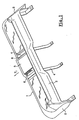
- FIG. 1 represents the underlying structure of a rear seat of a vehicle which comprises a front cross member 1, two lateral branches 2 and an anti-submarining sheet 3 parallel to the front cross member 1, the structure having substantially a rectangular shape .
- the front cross member 1 has a direction transverse to the vehicle while the branches 2 have a longitudinal direction.
- the structure also comprises two intermediate branches 4 which connect the front cross member 1 and the anti-submarine sheet 3.
- the front cross member 1 comprises between the two intermediate branches 4 a rectangular opening 11.
- a box 5 containing electronic equipment, for example a DVD player, is placed between the two intermediate branches so that its front face is flush with the front cross member 1 at the opening 11.
- the housing support 5 is fixed on the intermediate branches 4 by two plates 6.
- a plate 6, fixed on an intermediate branch 4 by means not shown, comprises a groove 61 cut in the longitudinal direction of the vehicle and opening in the direction of the arrow F1 towards the front of the vehicle.
- the plate 6 also comprises two levers 62 near the ends of the groove 61 in the direction substantially parallel to the groove 61 and a free end has a lug 63 projecting into the groove 61.
- the lug 63 has a first face 64 and a second face 65 oblique with respect to the direction of the groove 61, the first face 64 being directed towards the opening 11, the second face 65 being directed towards the anti-submarining sheet 3.
- the housing 5 has on each of the two faces parallel to the intermediate branches 4 two projecting pins and cooperating with the slot groove 61 of the plates 6.
- the first pin 51 is closer to the anti-submarining sheet 3 than the second pin 52.
- the first pin 51 is in contact with the bottom 66 not opening from the groove 61.
- the casing 5 When the casing 5 is put in place, the casing 5 is introduced through the opening 11 so that the pegs 51 are introduced and slide in the grooves 61. During the sliding in the groove 61, the pegs 51 meet the lugs 63 coming into contact with the first face 64. The pin 51 then slides on the first face 64 and the lug 63 is retracted by the bending of the lever 62. After the passage of two lugs by the first pin 51, the one it comes into contact with the bottom 66 of the groove, which blocks the possibility of translation of the housing 5 towards the rear. In this position, the pins 51, 52 are in contact with the lugs by the second faces 65 which, under the action of the lever 62, support the pins 51, 52 towards the bottom 66 of the groove and thus maintain the housing 5 in position.
- the anti-submarining plate In the event of a frontal impact on the vehicle and if a passenger occupies the seat above the housing, the anti-submarining plate is deformed in the direction of the arrow F1 under the action of the passenger's pelvis to a position shown in phantom mixed. During this deformation, the sheet 3 comes into contact with the rear face 53 of the housing 5 and pushes it forward. The movement is transmitted to the pins 51, 52 which push the levers 62 by pressing on the second faces 65. The lugs 63 retract elastically and the housing does not prevent the translation of the anti-submarine sheet.
- the invention is not limited to the mode of which has only been described by way of example.
- the housing can be held by other elastic or energy absorbing means.
- the seat structure may include an anti-tamper bar, possibly hinged on the sleepers in place of the sheet.
Landscapes
- Engineering & Computer Science (AREA)
- Mechanical Engineering (AREA)
- Aviation & Aerospace Engineering (AREA)
- Transportation (AREA)
- Seats For Vehicles (AREA)
Claims (6)
- Struktur eines Kraftfahrzeugsitzes aufweisend ein Gehäuse (5), einen Gehäuseträger (6), welcher das Gehäuse (5) mit der Struktur verbindet, einen Durchtauchverhinderungsquerträger (3), welcher sich gemäß einer vorherbestimmten Bahn im Falle eines Aufpralls auf das Fahrzeug verlagert oder verformt, wobei das Gehäuse (5) auf die vorherbestimmte Bahn gesetzt ist, dadurch gekennzeichnet, dass der Träger (6) des Gehäuses Haltemittel (51, 52, 62, 63) aufweist, welche die Verlagerung des Gehäuses (5) unter der Wirkung der Verlagerung oder der Verformung des Durchtauchverhinderungsquerträgers (3) erlauben.
- Struktur nach Anspruch 1, dadurch gekennzeichnet, dass die Haltemittel mindestens einen Klotz (51, 52) ausweisen, der an dem Gehäuse (5) befestigt ist und dessen Achse im Wesentlichen senkrecht zur vorherbestimmten Bahn ist, eine Platte (6), welche eine Nut (61) einer Richtung im Wesentlichen parallel zur vorherbestimmten Bahn aufweist und in welcher der Klotz (51, 52) gleitet, wobei die Platte (6) einen Finger (62, 63) ausweist, welcher auf den Klotz (51, 52) in einer Richtung entgegengesetzt zu der vorherbestimmten Bahn wirkt, wobei sich der Finger (62, 63) zurückzieht, wenn der Durchtauchverhinderungsquerträger (3) die Verlagerung des Gehäuses (5) bewirkt.
- Struktur nach Anspruch 2, dadurch gekennzeichnet, dass der Finger (62) auf den Klotz (51, 52) auf elastische Art und Weise wirkt.
- Struktur nach Anspruch 2, dadurch gekennzeichnet, dass der Finger (62) in einer schrägen Richtung zur vorherbestimmten Bahn wirkt.
- Struktur nach Anspruch 4, dadurch gekennzeichnet, dass der Finger (62) und die Nut (61) in der Platte (6) ausgestanzt sind, wobei der Finger einen Hebel (62) im Wesentlichen parallel zur Richtung der Nut (61) aufweist und einen Vorsprung (63), der in die Nut (62) vorragt und zwei im Verhältnis zu der Richtung schräge Flächen (64, 65) aufweist.
- Struktur nach Anspruch 1, dadurch gekennzeichnet, dass das Gehäuse (5) ein elektronisches Gerät enthält.
Applications Claiming Priority (2)
| Application Number | Priority Date | Filing Date | Title |
|---|---|---|---|
| FR0111354 | 2001-09-03 | ||
| FR0111354A FR2829076B1 (fr) | 2001-09-03 | 2001-09-03 | Structure de siege de vehicule automobile comportant un boitier |
Publications (2)
| Publication Number | Publication Date |
|---|---|
| EP1291237A1 EP1291237A1 (de) | 2003-03-12 |
| EP1291237B1 true EP1291237B1 (de) | 2006-01-18 |
Family
ID=8866894
Family Applications (1)
| Application Number | Title | Priority Date | Filing Date |
|---|---|---|---|
| EP20020292008 Expired - Lifetime EP1291237B1 (de) | 2001-09-03 | 2002-08-09 | Kraftfahrzeug-Sitzstruktur mit einem Gehäuse |
Country Status (3)
| Country | Link |
|---|---|
| EP (1) | EP1291237B1 (de) |
| DE (1) | DE60208765T2 (de) |
| FR (1) | FR2829076B1 (de) |
Families Citing this family (3)
| Publication number | Priority date | Publication date | Assignee | Title |
|---|---|---|---|---|
| FR2884780B1 (fr) * | 2005-04-25 | 2008-12-12 | Renault Sas | Agencement pour le support dans un vehicule automobile d'un boitier electronique |
| FR2969058A1 (fr) * | 2010-12-17 | 2012-06-22 | Renault Sa | Siege de vehicule automobile dote d'un dispositif anti sous-marinage ameliore |
| FR3089195B1 (fr) * | 2018-12-03 | 2022-03-04 | Psa Automobiles Sa | Vehicule comprenant un boitier electronique implante sous le coussin d’assise d’un siege |
Family Cites Families (2)
| Publication number | Priority date | Publication date | Assignee | Title |
|---|---|---|---|---|
| FR2798629B1 (fr) * | 1999-09-16 | 2001-11-09 | Faure Bertrand Equipements Sa | Assise d'un siege de vehicule automobile comportant une traverse d'anti-sous-marinage |
| JP2001120385A (ja) * | 1999-10-26 | 2001-05-08 | Ikeda Bussan Co Ltd | 車両用シート |
-
2001
- 2001-09-03 FR FR0111354A patent/FR2829076B1/fr not_active Expired - Fee Related
-
2002
- 2002-08-09 DE DE2002608765 patent/DE60208765T2/de not_active Expired - Lifetime
- 2002-08-09 EP EP20020292008 patent/EP1291237B1/de not_active Expired - Lifetime
Also Published As
| Publication number | Publication date |
|---|---|
| DE60208765T2 (de) | 2006-08-03 |
| EP1291237A1 (de) | 2003-03-12 |
| DE60208765D1 (de) | 2006-04-06 |
| FR2829076B1 (fr) | 2003-12-05 |
| FR2829076A1 (fr) | 2003-03-07 |
Similar Documents
| Publication | Publication Date | Title |
|---|---|---|
| EP0515897B1 (de) | Kontaktgeber für Karten mit Schaltkreis | |
| WO2001019641A1 (fr) | Assise d'un siege de vehicule automobile comportant une traverse d'anti-sous-marinage | |
| FR2474871A1 (fr) | Dispositif d'attache pour une ceinture de securite | |
| FR2817812A1 (fr) | Siege de vehicule automobile muni d'un ecran d'affichage video | |
| FR2862918A1 (fr) | Appui-tete pour siege de vehicule automobile avec corps d'appui | |
| CA2726659A1 (fr) | Siege pour vehicule blinde | |
| JP2003243090A (ja) | カード用コネクタ | |
| EP1291237A1 (de) | Kraftfahrzeug-Sitzstruktur mit einem Gehäuse | |
| EP1108450A1 (de) | Vorrichtung zur Halterung eines Schuhs auf einem Gleitbrett | |
| EP3898304B1 (de) | Kraftfahrzeug mit einem motorträger und einem fahrgestell | |
| JP3874260B2 (ja) | 車両用引き出し装置 | |
| EP1687185B1 (de) | Einen unteren teil umfassendes armaturenbrett, der sich bei einem aufprall bewegen kann, und entsprechendes fahrzeug | |
| FR2883525A1 (fr) | Appui-tete avec structure porteuse et corps d'appui | |
| EP2999617A1 (de) | Schnittstelle zur befestigung eines fahrzeugbodens und eines motorträgers aneinander zur abschwächung des gesetzes der entschleunigung während eines frontaufpralls | |
| US20030142610A1 (en) | Collapsible locking mechanism for an optical disk reading device | |
| JP3561831B2 (ja) | 車両用サンシェード装置 | |
| FR2658338A1 (fr) | Connecteur electrique pour carte portant un circuit. | |
| FR2779562A1 (fr) | Agencement pour le blocage d'un support de donnees dans un dispositif d'echange de donnees | |
| US20030161240A1 (en) | Disk guide device of compact disk player for automobile | |
| EP3210822A1 (de) | Vorrichtung zum einhaken eines fahrzeugsitzes ohne drehmoment in der halterung im falle einer kollision | |
| US7490338B2 (en) | Disc device | |
| EP0452464A1 (de) | Sicherheitsgurtverschluss. | |
| FR2659919A1 (fr) | Boucle pour ceinture de securite d'un vehicule. | |
| WO2024013438A1 (fr) | Boîte de rangement pour véhicule automobile comprenant un dispositif de fermeture d'un tiroir | |
| EP0079835A2 (de) | Sicherheitsgurtschnalle, insbesondere für Kraftfahrzeuge |
Legal Events
| Date | Code | Title | Description |
|---|---|---|---|
| PUAI | Public reference made under article 153(3) epc to a published international application that has entered the european phase |
Free format text: ORIGINAL CODE: 0009012 |
|
| AK | Designated contracting states |
Kind code of ref document: A1 Designated state(s): AT BE BG CH CY CZ DE DK EE ES FI FR GB GR IE IT LI LU MC NL PT SE SK TR |
|
| AX | Request for extension of the european patent |
Extension state: AL LT LV MK RO SI |
|
| AKX | Designation fees paid | ||
| REG | Reference to a national code |
Ref country code: DE Ref legal event code: 8566 |
|
| 17P | Request for examination filed |
Effective date: 20030905 |
|
| RBV | Designated contracting states (corrected) |
Designated state(s): BE DE GB |
|
| 17Q | First examination report despatched |
Effective date: 20050310 |
|
| GRAP | Despatch of communication of intention to grant a patent |
Free format text: ORIGINAL CODE: EPIDOSNIGR1 |
|
| RBV | Designated contracting states (corrected) |
Designated state(s): BE DE GB |
|
| GRAS | Grant fee paid |
Free format text: ORIGINAL CODE: EPIDOSNIGR3 |
|
| GRAA | (expected) grant |
Free format text: ORIGINAL CODE: 0009210 |
|
| AK | Designated contracting states |
Kind code of ref document: B1 Designated state(s): BE DE GB |
|
| REG | Reference to a national code |
Ref country code: GB Ref legal event code: FG4D Free format text: NOT ENGLISH |
|
| GBT | Gb: translation of ep patent filed (gb section 77(6)(a)/1977) |
Effective date: 20060223 |
|
| REF | Corresponds to: |
Ref document number: 60208765 Country of ref document: DE Date of ref document: 20060406 Kind code of ref document: P |
|
| PLBE | No opposition filed within time limit |
Free format text: ORIGINAL CODE: 0009261 |
|
| STAA | Information on the status of an ep patent application or granted ep patent |
Free format text: STATUS: NO OPPOSITION FILED WITHIN TIME LIMIT |
|
| 26N | No opposition filed |
Effective date: 20061019 |
|
| PGFP | Annual fee paid to national office [announced via postgrant information from national office to epo] |
Ref country code: DE Payment date: 20110823 Year of fee payment: 10 Ref country code: GB Payment date: 20110819 Year of fee payment: 10 |
|
| PGFP | Annual fee paid to national office [announced via postgrant information from national office to epo] |
Ref country code: BE Payment date: 20110811 Year of fee payment: 10 |
|
| BERE | Be: lapsed |
Owner name: *RENAULT S.A.S. Effective date: 20120831 |
|
| GBPC | Gb: european patent ceased through non-payment of renewal fee |
Effective date: 20120809 |
|
| PG25 | Lapsed in a contracting state [announced via postgrant information from national office to epo] |
Ref country code: BE Free format text: LAPSE BECAUSE OF NON-PAYMENT OF DUE FEES Effective date: 20120831 |
|
| PG25 | Lapsed in a contracting state [announced via postgrant information from national office to epo] |
Ref country code: GB Free format text: LAPSE BECAUSE OF NON-PAYMENT OF DUE FEES Effective date: 20120809 Ref country code: DE Free format text: LAPSE BECAUSE OF NON-PAYMENT OF DUE FEES Effective date: 20130301 |
|
| REG | Reference to a national code |
Ref country code: DE Ref legal event code: R119 Ref document number: 60208765 Country of ref document: DE Effective date: 20130301 |