EP1290754B1 - Antenne für automobile und bauteilesatz für eine solche - Google Patents
Antenne für automobile und bauteilesatz für eine solche Download PDFInfo
- Publication number
- EP1290754B1 EP1290754B1 EP01929580A EP01929580A EP1290754B1 EP 1290754 B1 EP1290754 B1 EP 1290754B1 EP 01929580 A EP01929580 A EP 01929580A EP 01929580 A EP01929580 A EP 01929580A EP 1290754 B1 EP1290754 B1 EP 1290754B1
- Authority
- EP
- European Patent Office
- Prior art keywords
- antenna
- outer conductor
- accordance
- coupler
- circuit
- Prior art date
- Legal status (The legal status is an assumption and is not a legal conclusion. Google has not performed a legal analysis and makes no representation as to the accuracy of the status listed.)
- Expired - Lifetime
Links
- 239000004020 conductor Substances 0.000 claims description 73
- 239000004033 plastic Substances 0.000 claims description 19
- 238000001746 injection moulding Methods 0.000 claims description 3
- 239000000463 material Substances 0.000 claims 1
- 229920000642 polymer Polymers 0.000 description 6
- 238000002347 injection Methods 0.000 description 5
- 239000007924 injection Substances 0.000 description 5
- 241000209035 Ilex Species 0.000 description 3
- 230000015572 biosynthetic process Effects 0.000 description 2
- 238000011161 development Methods 0.000 description 2
- 230000018109 developmental process Effects 0.000 description 2
- 238000004519 manufacturing process Methods 0.000 description 2
- 238000001465 metallisation Methods 0.000 description 2
- 240000003517 Elaeocarpus dentatus Species 0.000 description 1
- 229910000831 Steel Inorganic materials 0.000 description 1
- 230000006978 adaptation Effects 0.000 description 1
- 239000011324 bead Substances 0.000 description 1
- 238000002788 crimping Methods 0.000 description 1
- 238000005516 engineering process Methods 0.000 description 1
- 238000001125 extrusion Methods 0.000 description 1
- 230000002349 favourable effect Effects 0.000 description 1
- 239000002184 metal Substances 0.000 description 1
- 239000002991 molded plastic Substances 0.000 description 1
- 238000000465 moulding Methods 0.000 description 1
- 230000001681 protective effect Effects 0.000 description 1
- 239000000243 solution Substances 0.000 description 1
- 239000010959 steel Substances 0.000 description 1
- 238000009966 trimming Methods 0.000 description 1
Images



Classifications
-
- H—ELECTRICITY
- H01—ELECTRIC ELEMENTS
- H01Q—ANTENNAS, i.e. RADIO AERIALS
- H01Q1/00—Details of, or arrangements associated with, antennas
- H01Q1/12—Supports; Mounting means
- H01Q1/1207—Supports; Mounting means for fastening a rigid aerial element
-
- H—ELECTRICITY
- H01—ELECTRIC ELEMENTS
- H01Q—ANTENNAS, i.e. RADIO AERIALS
- H01Q1/00—Details of, or arrangements associated with, antennas
- H01Q1/12—Supports; Mounting means
-
- H—ELECTRICITY
- H01—ELECTRIC ELEMENTS
- H01Q—ANTENNAS, i.e. RADIO AERIALS
- H01Q1/00—Details of, or arrangements associated with, antennas
- H01Q1/27—Adaptation for use in or on movable bodies
- H01Q1/32—Adaptation for use in or on road or rail vehicles
Definitions
- the invention is based on an antenna with in the preamble of the claim 1 specified characteristics.
- Such an antenna is from EP 0 389 705 A2 known and has a coaxial coupler that has an outer conductor, an inner conductor and a support body defining the inner conductor in the outer conductor from a Plastic. Furthermore, such an antenna has a radiating element, which is electrically connected to the inner conductor of the coupler.
- Antenna is e.g. with the help of a foot part on the body panel of an automobile assembled.
- the antenna can be connected to the connector using a connector and by an antenna cable with a receiver provided in the vehicle get connected. For this purpose there is a hole in the body panel provided, on the edge of which the antenna is fixed with your foot section and a Ground contact to the body panel can be made.
- Antennas of the type mentioned are tuned to the frequency range in which they are to work. For different frequency ranges, eg for mobile phones in the C-network (450-465 MHz), D-network (890-960 MHz), E-network (1780-1920 MHz) or frequencies for navigation systems (G lobal P Positioning System, GPS , 1570 to 1580 MHz), the antennas are designed differently. This requires the production and stocking of different components.
- an antenna which is a radiator element Encapsulating sleeve in which an arrangement of coaxial Outer conductor, inner conductor and coupler is anchored to the radiator element.
- the present invention has for its object to show a way in which antennas of the type mentioned in the introduction can be standardized and easily assembled despite individual adaptation to different frequency ranges.
- the solution to this task is particularly important for cost reasons.
- the object is achieved by an antenna with the antenna in claim 1 specified features solved.
- Advantageous developments of the invention are Subject of the subclaims.
- Antennas according to the invention are primarily intended for high frequencies, in particular for the C-net, for the D-net, for the E-Unit, GPS, and for future UMTS applications (U niversal M obile T etecommunication S ervice), for which is the frequency range from 1990 to 2200 MHz.
- the inner conductor of the coupler and the radiator element can be conventional Be connected to the circuit on the circuit board.
- the inner conductor of the coupler and the radiator element with a hole in the circuit board or riveted caulk.
- a conductor track leads to each of these holes; preferably the holes are plated through, in particular by electrolytic metal deposition copper-plated, the metal layer provided in the bore Connects to the conductor track, which is on one side or on the other Side of the circuit board leads to the hole.
- the contact between the outer conductor of the coupler and the one or more for it provided contact area (s) on the circuit carrier plate is particularly designed simple and reliable if the contact surface is on the edge surface the circuit board.
- the contact between the outer conductor of the coupler and the one or so interacting contact surface (s) of the circuit board is special good and safe if the contact surface (s), as preferably provided, on one or two shoulder (s) formed on the edge of the circuit board is or are located on which the outer conductor with one on its inside proposed projection strikes, softer preferably ring-shaped is so that it is in any rotational angle position of the outer conductor on the support body with the contact surface (s) formed on the edge of the circuit board Can make contact.
- Such a shoulder can be manufactured particularly cheaply by starts from a somewhat wider circuit board, in this a hole in each of the places intended for the formation of the shoulders sets and this in the course of the formation of the conductor structures on the circuit board plated through by means of electrolytic metal deposition. After that the circuit board is trimmed at its edge so that the Separating cut is made through the hole (s) which are used for contacting the outer conductor of the coupler is or are provided.
- the support body is preferably in the direction facing the radiator element
- the outer conductor is preferably above the outer conductor and vice versa in the opposite direction over the support body. This way can be achieved that the outer conductor does not shield the circuit board, partially also does not shield the inner conductor.
- the antenna tapers from its connector end gradually to the tip of the radiator element and can on this Way in a preferably conically tapering plastic sleeve on the outside are encapsulated, giving the antenna a compact and stylish Structure maintains. In the protruding downwards over the support body A coaxial connector can be inserted in a protected manner.
- the support body in this development of the invention is not downwards protruding from the outer conductor are in the support body on its underside, that is the side facing away from the radiator element, preferably recesses for the engagement of a rotary key provided with which the support body of the underside into the outer conductor and the necessary pressure when striking the contact surfaces of the circuit board at the associated stop of the outer conductor can be generated.
- Circuit board with different circuits to customize the antennas are kept in stock at different frequency ranges, should correspond in their dimensions so that the mechanical Conditions when mounting antennas for different frequency ranges do not differentiate.
- FIG. 1 shows an elongated, approximately rectangular circuit carrier plate 1, which is a symbolically represented circuit 2 of conductor tracks and in SMD technology manufactured circuit parts carries.
- A largely lengthways the circuit carrier 1 running conductor connects a hole 3 near the upper end of the circuit board 1 with a Bore 4 near the lower end of the circuit board 1.
- At the Upper bore 3 is a in the longitudinal direction of the circuit board 1st extending radiator element 5 riveted to the circuit carrier plate 1.
- On the lower bore 4 is the inner conductor 6 of a coaxial coupler with the Circuit board 1 riveted.
- the radiator element 5 and the inner conductor 6 are aligned coaxially.
- the radiator element 5 is designed as a socket Inner conductor 6 as a slotted socket.
- the Circuit carrier plate 1 On the two longitudinal edges of the Circuit carrier plate 1, which is parallel to the longitudinal axis 7 of the radiator element 5 and the inner conductor 6, there are two shoulders 8 and 9; she are arranged mirror-symmetrically with respect to the longitudinal axis 7.
- the two Shoulders 8 and 9 are formed on the edge surface 10 of the circuit board 1; shoulders 8 and 9 are the remains of two originally existing, metal-plated holes, of which subsequently by trimming the edge of the circuit board 1 more than half of its circumference was removed.
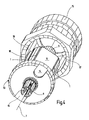
- the assembly shown in Figure 1 is in an injection mold with a Injection molded plastic around the support body shown in Figure 2 and Figure 3 11 to form.
- the circuit board 1 is almost completely in the Plastic embedded, with the exception of their two longitudinal edges, on which the shoulders 8 and 9 are located with their contact surfaces 8a and 9a.
- the circuit carrier plate 1 also the inner conductor 6 and the radiator element 5 embedded a bit in the plastic.
- the support body 11 is essentially an elongated, essentially prismatic Body 12 with an adjoining circular threaded flange 13, on the lateral surface of a screw thread during injection molding was trained. At the bottom of the threaded flange 13 are in diagonal arrangement two recesses 14, in which for mounting the antenna a rotary key can intervene.
- the contour of the The stop surface of the stop 17 is conical with respect to the longitudinal axis 7 trained and designed such that the stop 17 not only a firm contact with the contact surfaces 8a and 9a, but also on one radially somewhat further outward position of the threaded flange a firm Establishes contact with him; this has the advantage that none from below Moisture between the support body 11 and the sleeve of the outer conductor 15 can rise up into the area of the radiator.
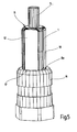
- Figure 5 shows the component shown in Figures 2 and 3 after it is firmly screwed into the sleeve of the outer conductor 15.
- FIG. 6 shows the arrangement shown in FIG. 5 surrounded by a sleeve 18 made of plastic, which on the outside has the shape of a slim cone Has.
- This sleeve 18 is made of plastic and is preferably already before
- the assembly step shown in FIG. 4 by injection molding around the outer conductor 15 splashed around so that it is firmly and waterproof anchored in the sleeve 18.
- the contour of the inside of the sleeve 18 is chosen so that it from the outer conductor 16 protruding portion of the support body 11 surrounds relatively closely and surrounds the radiator element 5 with greater latitude.
- Figure 6 also shows that in this embodiment to the radiator element 5 a further radiator part 5a connects to the intended use of the antenna to achieve a suitable steel length.
- the additional radiator part 5a is preferably around a flexible metallic strand, which is covered with a plastic is encased.
- the sleeve 18 projects beyond the lower edge of the outer conductor 15 and is on provided its lower edge with an inwardly projecting bead 19 with whose help they are snapped onto a foot part of the antenna, not shown can.
- the foot part can in turn be used to attach the antenna to the body panel of an automobile and to pass the inner conductor through a hole serve in the body panel.
Landscapes
- Support Of Aerials (AREA)
- Details Of Aerials (AREA)
Description
- Dadurch, daß die Anpassung der Antenne mittels einer Schaltung erfolgt, weiche sich auf einer zwischen dem Strahlerelement und dem Innenleiter des Kupplers angeordneten Schaltungsträgerplatte befindet und sowohl mit dem Innenleiter des Kupplers als auch mit dem Strahlerelement elektrisch leitend verbunden ist, kann das Strahlerelement für die in Frage kommenden unterschiedlichen Frequenzbereiche übereinstimmend ausgebildet sein. Die Anpassung erfolgt durch die Schaltung auf der Schaltungsträgerplatte, deren äußere Abmessungen für die unterschiedlichen Frequenzbereiche übereinstimmend wählbar sind. Der mechanische Aufbau der Antenne kann deshalb für die unterschiedlichen Frequenzbereiche derselbe sein.
- Dadurch, daß sich die Schaltungsträgerplatte in der Längsrichtung des Strahlerelementes erstreckt, kann die Schaltung mit einer Leiterbahnführung in der Längsrichtung des Strahlerelementes einen Bestandteil des Strahlers bilden, so daß dieser sich mit seiner wirksamen Länge vom Innenleiter des Kupplers über die Schaltungsträgerplatte zum Strahlerelement und vorzugsweise über dieses hinaus in einen abschließenden Strahlerteil erstreckt. Dieser Strahlerteil ist aus Sicherheitsgründen vorzugsweise biegsam ausgebildet. Um den biegsamen Strahlerteil mit dem Strahlerelement verbinden zu können, ist das Strahlerelement zweckmäßigerweise als Buchse ausgebildet, in welche der biegsame Strahlerteil gesteckt werden kann.
- Durch die Anordnung der Schaltungsträgerplatte in der Längsrichtung des Strahlerelementes ist es möglich, die Leiterplatte zusammen mit dem Strahlerelement und mit dem biegsamen Strahlerteil in einer schlanken Schutzhülse unterzubringen. Dadurch läßt sich ein besonders ansprechendes Erscheinungsbild der Antenne erreichen, was für den Einsatz auf Automobilen wichtig ist.
- Dadurch, daß die Schaltungsträgerplatte in das Stützteil eingebettet ist, erhält man einen sehr kompakten Aufbau, spart gesonderte Befestigungsmittel für die Schaltungsträgerplatte und erreicht einen optimalen Schutz für sie.
- Durch das Einbetten der Schaltungsträgerplatte in das Stützteil werden die Anschlüsse der Schaltung zum Innenleiter des Kupplers auf der einen Seite und zum Strahlerelement auf der anderen Seite gesichert und dauerhaft geschützt.
- Durch das Einbetten der Schaltungsträgerplatte in das Stützteil ist die Antenne kompakt und mechanisch sehr stabil.
- Das Einbetten der Schaltungsträgerplatte in den Kunststoff des Stützteils kann so erfolgen, daß eine oder zwei zur Kontaktgabe mit dem Außenleiter des Kupplers bestimmte Kontaktflächen nicht mit eingebettet werden, sondern freiliegen. Die Kontaktgabe zum Außenleiter des Kupplers gestaltet sich besonders einfach, weil dieser ohnehin so ausgebildet und dafür bestimmt ist, das Stützteil des Kupplers fest zu umschließen. Dabei wird die Kontaktgabe zwischen der nicht in dem Kunststoff des Stützteils eingebetteten Kontaktfläche(n) ohne besonderen Aufwand mitgeliefert.
- Die für die Montage der Antenne erforderlichen Schritte sind für Antennen, die auf unterschiedliche Frequenzbereiche abgestimmt sind dieselben.
- Das Einbetten der Schaltungsträgerplatte in das Stützteil kann kostensparend dadurch erfolgen, daß die Schaltungsträgerplatte mit dem Kunststoff des Stützteils umspritzt wird. Dazu nimmt man eine Spritzgießform, welche z.B. so ausgebildet ist, daß die Schaltungsträgerplatte mit dem an ihr bereits befestigten Innenleiter des Kupplers und mit dem an ihr bereits befestigten Strahlerelement in eine Spritzgießform oder in eine Mehrfach-Spritzgießform gelegt wird.
- Das Strahlerelement ist in einer Hülse aus einem Kunststoff gekapselt und vor Witterungseinflüssen geschützt. Die Hülse erstreckt sich auch über den Kuppler und ist auf dessen Außenseite verankert.
- Figur 1
- zeigt in stark vergrößertem Maßstab eine Schaltungsträgerplatte, an welcher ein Strahlerelement und ein Innenleiter eines Kupplers befestigt sind, in einer Schrägansicht,
- Figur 2
- zeigt die Anordnung aus Figur 1, mit einem Stützkörper aus Kunststoff umspritzt, in einer Seitenansicht,
- Figur 3
- zeigt das in Figur 2 dargestellte Bauteil in einer Schrägansicht, schräg von unten gesehen,
- Figur 4
- zeigt das in den Figuren 2 und 3 dargestellte Bauteil beim Einführen in einen als Schraubhülse ausgebildeten Außenleiter in einer Schrägansicht,
- Figur 5
- zeigt das in den Figuren 2 und 3 dargestellte Bauteil eingesetzt in den Außenleiter gemäß Figur 4, und
- Figur 6
- zeigt die Anordnung aus Figur 5, eingefügt in eine Hülse aus Kunststoff.
Claims (11)
- Antenne für Automobile, mit einem koaxialen Kuppler, der einen Außenleiter (15), einen Innenleiter (6) und einen den Innenleiter (6) im Außenleiter (15) festlegenden Stützkörper (11) aus einem Kunststoff hat,
mit einem Strahlerelement (5), welches elektrisch leitend mit dem Innenleiter (6) des Kupplers verbunden ist, und wobei
sich eine Schaltung (2), welche zur Anpassung der Antenne dient, auf einer zwischen dem Strahlerelement (5) und dem Innenleiter (6) des Kupplers angeordneten, sich in der Richtung des Strahlerelementes (5) erstreckenden Schaltungsträgerplatte (1) befindet und sowohl mit dem Innenleiter (6) des Kupplers als auch mit dem Strahlerelement (5) elektrisch leitend verbunden ist,
dadurch gekennzeichnet, daß die Antenne eine das Strahlerelement (5) kapselnden Hülse (18) aus einem Kunststoff, in welcher der Außenleiter (15) des Kupplers verankert ist, aufweist und
daß die Schaltungsträgerplatte (1) in den Stützkörper (11) eingebettet ist und an ihrem Rand eine vom Kunststoff des Stützkörpers (11) nicht bedeckte Kontaktfläche (8a, 9a) hat, welche zur Kontaktgabe mit dem Außenleiter (15) des Kupplers ausgebildet ist. - Antenne nach Anspruch 1, dadurch gekennzeichnet, daß die Schaltungsträgerplatte (1) mit dem Kunststoff des Stützkörpers (11) umspritzt ist.
- Antenne nach Anspruch 1 oder 2, dadurch gekennzeichnet, daß der Innenleiter (6) des Kupplers und das Strahlerelement (5) jeweils mit einer Bohrung (3,4) im Bereich einer Leiterbahn vernietet oder verstemmt sind.
- Antenne nach einem der vorstehenden Ansprüche, dadurch gekennzeichnet, daß sich die zur Kontaktgabe mit dem Außenleiter (15) des Kupplers bestimmte Kontaktfläche (8a, 9a) an der Randfläche (10) der Schaltungsträgerplatte (1) befindet.
- Antenne nach einem der vorstehenden Ansprüche, dadurch gekennzeichnet, daß der Stützkörper (11) einen mit einem Außengewinde versehenen Abschnitt hat und daß der Außenleiter (15) ein Innengewinde (16) hat, mit welchem er auf das Außengewinde des Stützkörpers (11) geschraubt ist.
- Antenne nach Anspruch 4 oder nach Anspruch 4 und Anspruch 5, dadurch gekennzeichnet, daß sich die Kontaktfläche (8a, 9a) an einer am Rand der Schaltungsträgerplatte (1) ausgebildeten Schulter (8, 9) befindet, an welcher der Außenleiter (15) mit einem an seiner Innenseite vorgesehenen Anschlag (17) anschlägt.
- Antenne nach Anspruch 6, dadurch gekennzeichnet, daß die Schulter (8, 9) ein durch Abtrennen eines Teils der Schaltungsträgerplatte (1) entstandener Rest einer durchkontaktierten Bohrung der Schaltungsträgerplatte (1) ist.
- Antenne nach Anspruch 6 oder 7, dadurch gekennzeichnet, daß an den beiden sich in Längsrichtung des Strahlerelementes (5) erstreckenden Rändern der Schaltungsträgerplatte (1) jeweils eine solche Schulter (8, 9) angeordnet ist.
- Antenne nach einem der vorstehenden Ansprüche, dadurch gekennzeichnet, daß der Stützkörper (11) in der zum Strahlerelement (5) weisenden Richtung über den Außenleiter (15) vorsteht und daß der Außenleiter (15) in der Gegenrichtung über den Stützkörper (11) vorsteht.
- Antenne nach einem der vorstehenden Ansprüche in Verbindung mit Anspruch 5, dadurch gekennzeichnet, daß der Stützkörper (11) an seiner dem Strahlerelement (5) abgewandten Seite Ausnehmungen (14) für den Eingriff eines Drehschlüssels hat.
- Bauteilesatz für eine Antenne nach einem der vorstehenden Ansprüche mit mehreren in ihren Abmessungen übereinstimmenden Schaltungsträgerplatten (1), welche unterschiedliche Schaltungen tragen.
Applications Claiming Priority (5)
| Application Number | Priority Date | Filing Date | Title |
|---|---|---|---|
| DE10027687 | 2000-05-28 | ||
| DE10027687 | 2000-05-28 | ||
| DE10036591A DE10036591C2 (de) | 2000-05-28 | 2000-07-27 | Antenne für Automobile und Bauteilesatz für eine solche |
| DE10036591 | 2000-07-27 | ||
| PCT/EP2001/004421 WO2001095428A1 (de) | 2000-05-28 | 2001-04-19 | Antenne für automobile und bauteilesatz für eine solche |
Publications (2)
| Publication Number | Publication Date |
|---|---|
| EP1290754A1 EP1290754A1 (de) | 2003-03-12 |
| EP1290754B1 true EP1290754B1 (de) | 2003-12-03 |
Family
ID=26005958
Family Applications (1)
| Application Number | Title | Priority Date | Filing Date |
|---|---|---|---|
| EP01929580A Expired - Lifetime EP1290754B1 (de) | 2000-05-28 | 2001-04-19 | Antenne für automobile und bauteilesatz für eine solche |
Country Status (2)
| Country | Link |
|---|---|
| EP (1) | EP1290754B1 (de) |
| WO (1) | WO2001095428A1 (de) |
Family Cites Families (3)
| Publication number | Priority date | Publication date | Assignee | Title |
|---|---|---|---|---|
| US4882592A (en) * | 1989-02-03 | 1989-11-21 | Radio Frequency Systems, Inc. | Motor vehicle antenna mount |
| JPH0642607B2 (ja) * | 1989-03-28 | 1994-06-01 | 日本通信電線株式会社 | 移動無線機用空中線 |
| DE4336633A1 (de) * | 1993-10-27 | 1995-05-04 | Rr Elektronische Geraete Gmbh | Koaxialantenne |
-
2001
- 2001-04-19 EP EP01929580A patent/EP1290754B1/de not_active Expired - Lifetime
- 2001-04-19 WO PCT/EP2001/004421 patent/WO2001095428A1/de not_active Ceased
Also Published As
| Publication number | Publication date |
|---|---|
| WO2001095428A1 (de) | 2001-12-13 |
| EP1290754A1 (de) | 2003-03-12 |
Similar Documents
| Publication | Publication Date | Title |
|---|---|---|
| DE19620856B4 (de) | Kuppler für einen koaxialen Steckverbinder | |
| DE3850872T2 (de) | Tragbare Antenne. | |
| DE10207703B4 (de) | Antenne für eine Empfangs- und/oder Sendeeinrichtung insbesondere als Dachantenne für Kraftfahrzeuge | |
| DE102019130860B4 (de) | Schraubbare Fahrzeugantenne | |
| EP1919026A1 (de) | Montagebaugruppe für eine Kraftfahrzeugantenne | |
| EP1751819A2 (de) | Eingebettete planare antenne und dazugehöriges abstimmungverfahren | |
| DE102016114093B4 (de) | Breitbandige omnidirektionale Antenne, insbesondere für Schienenfahrzeuge und ein solches Schienenfahrzeug | |
| EP1318565B1 (de) | Antenne, insbesondere Mobilfunkantenne, mit einer Zentrierhilfe bei ihrer Herstellung | |
| WO2015067449A1 (de) | Vorrichtung zum positionsgerechten befestigen einer antennenanordnung an einer fläche | |
| DE10036591C2 (de) | Antenne für Automobile und Bauteilesatz für eine solche | |
| EP3430679B1 (de) | Antennenschutzhaube für fahrzeuge | |
| DE2727230A1 (de) | Funkenstreckenvorrichtung fuer einen kathodenstrahlroehrensockel | |
| EP1698543B1 (de) | Dachmodul mit Antenne | |
| WO2013050440A1 (de) | Krafteinleitungsring für geschäumte radome | |
| DE10327349A1 (de) | Batterieverbinder-Anordnung | |
| EP1290754A1 (de) | Antenne für automobile und bauteilesatz für eine solche | |
| DE20012981U1 (de) | Antenne für Automobile | |
| EP0710998B1 (de) | Antenne für ein Kraftfahrzeug | |
| DE19538725C1 (de) | Klinkenbuchse | |
| EP1797616A1 (de) | Antennengehäuse und verfahren zur herstellung eines antennengehäuses | |
| DE69526059T2 (de) | Leitungselement zum Verbinden und Stützen der Leitfähigkeit zwischen zwei Verbindungselementen | |
| DE19807278C2 (de) | Winkelstecker an einem Koaxialkabel | |
| EP1815554B1 (de) | Kopplungsleitungen f]r einen yig-filter oder yig-oszillator und verfahren zur herstellung der kopplungsleitungen | |
| DE69515281T2 (de) | Kraftfahrzeugantenne und Anpassungsvorrichtung mit aktiver Impedanz für eine solche Antenne | |
| DE102013219377A1 (de) | Antennenanordnung mit antenneneinheit und verbindereinheit |
Legal Events
| Date | Code | Title | Description |
|---|---|---|---|
| PUAI | Public reference made under article 153(3) epc to a published international application that has entered the european phase |
Free format text: ORIGINAL CODE: 0009012 |
|
| 17P | Request for examination filed |
Effective date: 20021213 |
|
| AK | Designated contracting states |
Kind code of ref document: A1 Designated state(s): AT BE CH CY DE DK ES FI FR GB GR IE IT LI LU MC NL PT SE TR |
|
| AX | Request for extension of the european patent |
Extension state: AL LT LV MK RO SI |
|
| GRAH | Despatch of communication of intention to grant a patent |
Free format text: ORIGINAL CODE: EPIDOS IGRA |
|
| GRAS | Grant fee paid |
Free format text: ORIGINAL CODE: EPIDOSNIGR3 |
|
| GRAA | (expected) grant |
Free format text: ORIGINAL CODE: 0009210 |
|
| RAP1 | Party data changed (applicant data changed or rights of an application transferred) |
Owner name: WILHELM SIHN JR. GMBH & CO. KG |
|
| RAP3 | Party data changed (applicant data changed or rights of an application transferred) |
Owner name: WILHELM SIHN JR. GMBH & CO. KG |
|
| AK | Designated contracting states |
Kind code of ref document: B1 Designated state(s): DE FR GB IT SE |
|
| REG | Reference to a national code |
Ref country code: GB Ref legal event code: FG4D Free format text: NOT ENGLISH |
|
| REG | Reference to a national code |
Ref country code: SE Ref legal event code: TRGR |
|
| REG | Reference to a national code |
Ref country code: IE Ref legal event code: FG4D Free format text: GERMAN |
|
| REF | Corresponds to: |
Ref document number: 50101090 Country of ref document: DE Date of ref document: 20040115 Kind code of ref document: P |
|
| GBT | Gb: translation of ep patent filed (gb section 77(6)(a)/1977) |
Effective date: 20040123 |
|
| LTIE | Lt: invalidation of european patent or patent extension |
Effective date: 20031203 |
|
| ET | Fr: translation filed | ||
| REG | Reference to a national code |
Ref country code: IE Ref legal event code: FD4D |
|
| PLBE | No opposition filed within time limit |
Free format text: ORIGINAL CODE: 0009261 |
|
| STAA | Information on the status of an ep patent application or granted ep patent |
Free format text: STATUS: NO OPPOSITION FILED WITHIN TIME LIMIT |
|
| 26N | No opposition filed |
Effective date: 20040906 |
|
| PGFP | Annual fee paid to national office [announced via postgrant information from national office to epo] |
Ref country code: FR Payment date: 20110427 Year of fee payment: 11 Ref country code: SE Payment date: 20110419 Year of fee payment: 11 |
|
| PGFP | Annual fee paid to national office [announced via postgrant information from national office to epo] |
Ref country code: GB Payment date: 20110419 Year of fee payment: 11 |
|
| PGFP | Annual fee paid to national office [announced via postgrant information from national office to epo] |
Ref country code: IT Payment date: 20110422 Year of fee payment: 11 |
|
| REG | Reference to a national code |
Ref country code: SE Ref legal event code: EUG |
|
| GBPC | Gb: european patent ceased through non-payment of renewal fee |
Effective date: 20120419 |
|
| REG | Reference to a national code |
Ref country code: FR Ref legal event code: ST Effective date: 20121228 |
|
| PG25 | Lapsed in a contracting state [announced via postgrant information from national office to epo] |
Ref country code: GB Free format text: LAPSE BECAUSE OF NON-PAYMENT OF DUE FEES Effective date: 20120419 |
|
| PG25 | Lapsed in a contracting state [announced via postgrant information from national office to epo] |
Ref country code: SE Free format text: LAPSE BECAUSE OF NON-PAYMENT OF DUE FEES Effective date: 20120420 Ref country code: FR Free format text: LAPSE BECAUSE OF NON-PAYMENT OF DUE FEES Effective date: 20120430 Ref country code: IT Free format text: LAPSE BECAUSE OF NON-PAYMENT OF DUE FEES Effective date: 20120419 |
|
| PGFP | Annual fee paid to national office [announced via postgrant information from national office to epo] |
Ref country code: DE Payment date: 20180220 Year of fee payment: 18 |
|
| REG | Reference to a national code |
Ref country code: DE Ref legal event code: R119 Ref document number: 50101090 Country of ref document: DE |
|
| PG25 | Lapsed in a contracting state [announced via postgrant information from national office to epo] |
Ref country code: DE Free format text: LAPSE BECAUSE OF NON-PAYMENT OF DUE FEES Effective date: 20191101 |