EP1287327B1 - Automate pour l'analyse biologique - Google Patents
Automate pour l'analyse biologique Download PDFInfo
- Publication number
- EP1287327B1 EP1287327B1 EP01915458A EP01915458A EP1287327B1 EP 1287327 B1 EP1287327 B1 EP 1287327B1 EP 01915458 A EP01915458 A EP 01915458A EP 01915458 A EP01915458 A EP 01915458A EP 1287327 B1 EP1287327 B1 EP 1287327B1
- Authority
- EP
- European Patent Office
- Prior art keywords
- biochip
- processing device
- biological analysis
- reactor
- analysis according
- Prior art date
- Legal status (The legal status is an assumption and is not a legal conclusion. Google has not performed a legal analysis and makes no representation as to the accuracy of the status listed.)
- Expired - Lifetime
Links
Images


Classifications
-
- B—PERFORMING OPERATIONS; TRANSPORTING
- B01—PHYSICAL OR CHEMICAL PROCESSES OR APPARATUS IN GENERAL
- B01L—CHEMICAL OR PHYSICAL LABORATORY APPARATUS FOR GENERAL USE
- B01L3/00—Containers or dishes for laboratory use, e.g. laboratory glassware; Droppers
- B01L3/50—Containers for the purpose of retaining a material to be analysed, e.g. test tubes
- B01L3/508—Containers for the purpose of retaining a material to be analysed, e.g. test tubes rigid containers not provided for above
- B01L3/5085—Containers for the purpose of retaining a material to be analysed, e.g. test tubes rigid containers not provided for above for multiple samples, e.g. microtitration plates
-
- G—PHYSICS
- G01—MEASURING; TESTING
- G01N—INVESTIGATING OR ANALYSING MATERIALS BY DETERMINING THEIR CHEMICAL OR PHYSICAL PROPERTIES
- G01N35/00—Automatic analysis not limited to methods or materials provided for in any single one of groups G01N1/00 - G01N33/00; Handling materials therefor
- G01N35/00029—Automatic analysis not limited to methods or materials provided for in any single one of groups G01N1/00 - G01N33/00; Handling materials therefor provided with flat sample substrates, e.g. slides
-
- G—PHYSICS
- G01—MEASURING; TESTING
- G01N—INVESTIGATING OR ANALYSING MATERIALS BY DETERMINING THEIR CHEMICAL OR PHYSICAL PROPERTIES
- G01N35/00—Automatic analysis not limited to methods or materials provided for in any single one of groups G01N1/00 - G01N33/00; Handling materials therefor
- G01N35/02—Automatic analysis not limited to methods or materials provided for in any single one of groups G01N1/00 - G01N33/00; Handling materials therefor using a plurality of sample containers moved by a conveyor system past one or more treatment or analysis stations
- G01N35/025—Automatic analysis not limited to methods or materials provided for in any single one of groups G01N1/00 - G01N33/00; Handling materials therefor using a plurality of sample containers moved by a conveyor system past one or more treatment or analysis stations having a carousel or turntable for reaction cells or cuvettes
-
- G—PHYSICS
- G01—MEASURING; TESTING
- G01N—INVESTIGATING OR ANALYSING MATERIALS BY DETERMINING THEIR CHEMICAL OR PHYSICAL PROPERTIES
- G01N35/00—Automatic analysis not limited to methods or materials provided for in any single one of groups G01N1/00 - G01N33/00; Handling materials therefor
- G01N35/00029—Automatic analysis not limited to methods or materials provided for in any single one of groups G01N1/00 - G01N33/00; Handling materials therefor provided with flat sample substrates, e.g. slides
- G01N2035/00099—Characterised by type of test elements
- G01N2035/00158—Elements containing microarrays, i.e. "biochip"
-
- G—PHYSICS
- G01—MEASURING; TESTING
- G01N—INVESTIGATING OR ANALYSING MATERIALS BY DETERMINING THEIR CHEMICAL OR PHYSICAL PROPERTIES
- G01N35/00—Automatic analysis not limited to methods or materials provided for in any single one of groups G01N1/00 - G01N33/00; Handling materials therefor
- G01N2035/00465—Separating and mixing arrangements
- G01N2035/00514—Stationary mixing elements
-
- Y—GENERAL TAGGING OF NEW TECHNOLOGICAL DEVELOPMENTS; GENERAL TAGGING OF CROSS-SECTIONAL TECHNOLOGIES SPANNING OVER SEVERAL SECTIONS OF THE IPC; TECHNICAL SUBJECTS COVERED BY FORMER USPC CROSS-REFERENCE ART COLLECTIONS [XRACs] AND DIGESTS
- Y10—TECHNICAL SUBJECTS COVERED BY FORMER USPC
- Y10T—TECHNICAL SUBJECTS COVERED BY FORMER US CLASSIFICATION
- Y10T436/00—Chemistry: analytical and immunological testing
- Y10T436/11—Automated chemical analysis
- Y10T436/111666—Utilizing a centrifuge or compartmented rotor
-
- Y—GENERAL TAGGING OF NEW TECHNOLOGICAL DEVELOPMENTS; GENERAL TAGGING OF CROSS-SECTIONAL TECHNOLOGIES SPANNING OVER SEVERAL SECTIONS OF THE IPC; TECHNICAL SUBJECTS COVERED BY FORMER USPC CROSS-REFERENCE ART COLLECTIONS [XRACs] AND DIGESTS
- Y10—TECHNICAL SUBJECTS COVERED BY FORMER USPC
- Y10T—TECHNICAL SUBJECTS COVERED BY FORMER US CLASSIFICATION
- Y10T436/00—Chemistry: analytical and immunological testing
- Y10T436/25—Chemistry: analytical and immunological testing including sample preparation
- Y10T436/2575—Volumetric liquid transfer
Definitions
- Biochips can analyze in parallel a very large number of molecules. It is essentially nucleic acids and proteins.
- the basic principle is the recognition and pairing of two molecules, which have affinities.
- One of the collections of molecules is fixed, in the form of mini or micro-deposits, on a solid support, fabric, glass slide, silicon chip ...
- the other molecule which is marked, generally in solution, is brought into contact with the samples deposited on the solid support. After an incubation time, the excess of labeled molecule is removed and the support is thoroughly washed. It is then a question of detecting and quantifying the signal emitted by the molecules retained on the deposits. In some cases, the molecule retained may be "unhooked" from the deposits and a new molecule may be tested with the same solid support.
- the labeled molecule is a rare and / or expensive element.
- the necessary volume must be minimized.
- the other reagents, and in particular the washing products, are inexpensive and the reduction in the volumes used is much less important.
- EP947819 discloses a biochip processing automaton for biological analysis consisting of a centrifuge comprising a rotor supporting a reactor. The spreading takes place by centrifugal movement of the liquid deposited on a horizontal biochip.
- Other centrifugal machines such as US5589400 or US4853188 deposit liquids on the surface of microscope slides placed vertically at the end of the spokes of a rotor.
- the use of a mobile slide for spreading a liquid on a slide for biological analysis is known, for example by EP047189.
- automaton as defined by claims 1 to 13 capable of performing without human intervention the processing of biochips and the acquisition of signals for their analysis.
- the automaton makes it possible to treat a large number of biochips. Its simplicity makes it a relatively inexpensive piece of equipment.
- the heart of the device is a low speed centrifuge whose angular position of the rotor can be fixed precisely, thanks to an encoder for example.
- the rotor removable or not, consists of a hub on which are fixed spokes. Each ray carries at its end a reactor which will be described later.
- the lid of the centrifuge has different elements:
- a number of regularly spaced fixed nozzles equal to the number of rotor reactors and located on a circumference whose radius is equal to that of the center of the reactors, so as to dispense liquid therein.
- These nozzles are connected by calibrated catheters to the lid of a hermetic enclosure which comprises a number of tubes containing the labeled molecules.
- This chamber can be put under pressure, given for a given time, thanks to a gas cylinder, for example, which has the effect of discharging through the catheters to the reactors a same volume of liquids contained in the tubes.
- This chamber can be cooled by any method to ensure good conservation of the labeled molecules.
- a mechanical device for translation on a spoke makes it possible to pull at the periphery, then to bring back to its initial position a sliding piece carrying biochips of each reactor or in other cases the reactors themselves, successively.
- This device may consist of a guided rack, driven by a pinion integral with a fixed electric motor shaft.
- a finger placed at the portion closest to the center of the movable member can go down into the centrifuge and back through a cam, for example. This finger allows the translation device to hang the sliding part or the reactor.
- the casing of the centrifuge comprises a slot which can be closed by a part integral with the mechanical translation device and which passes the slide door biochip or the reactor. These are thus placed in the field of the signal acquisition system.
- the envelope of the centrifuge may be provided with one or more horizontal telescopic nozzles for either injecting reagent into each reactor or aspirate the reagents it contains.
- the shape of the bottom of the chamber of the centrifuge is designed to allow the complete evacuation of the reagents used.
- the temperature inside the centrifuge is regulated.
- the very low speed rotation of the reactors improves the uniformity of the temperature. If necessary, the hygrometry of the air in the chamber can be controlled.
- the bottom of the centrifuge and / or the inside of the lid may be provided with a circular element of suitable shape to cause movements of reactor parts.
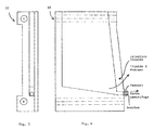
- the reactors (1) illustrated in FIGS. 1 to 3, fixed at the end of the spokes (7) of the rotor (8) of the centrifuge (9) illustrated in FIG. 4, are inclined relative to the vertical passing through the radius, in a plane passing through this radius.
- the body (3) of the reactor which is traversed by the radius (7) of the rotor (8). It has on one of its two large faces a guide. It can, at the lower part of the outer face, comprise an orifice closed by a heavy plug applied by means of a spring and which thanks to the centripetal force deviates from the surface and releases the orifice. It can also on the same face have another orifice closed by a cap from the inside, maintained in support by a spring. By applying a telescopic nozzle on this orifice, it is possible to inject a liquid under pressure into the reactor.
- a slide (4) biochip holder (2) which when it is provided with the biochip and engaged fund in its guidance, closes one of the two large faces of the reactor.
- the biochip gate can be moved one or two millimeters in its guide, without affecting the tightness of the reactor, to improve the contact of the deposits with the reagents. It can be moved away from its original position six or seven millimeters outside to open the reactor and allow the flow of its contents. It can finally be removed from its original position by a few centimeters to exit the enclosure of the centrifuge and be placed in the field of the signal acquisition system. It is the mechanical device of translation evoked above which activates the door biochips or in other cases the reactors.
- An agitator (5) composed of a lamella (6) which can either bear on the lower part of the biochip (2) forming a solid angle which retains a small volume of liquid, or from this position come to apply on the biochip "spreading" on its surface and without air bubble the volume of liquid retained, either enter completely into the body of the reactor to allow the sliding of the biochip gate.
- the continuous passage between these three positions causes the washing liquid to be projected onto the active surface of the biochip.
- the rotation of the reactors (1) at low speed causes the accumulation of the liquid contained to the outside. Stopping this rotation cancels this accumulation and creates a reflux of the liquid to the rotor (8). The succession of rotations and stops agitates the liquid and accelerates the washing of biochips.
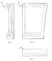
- reactors can be designed, such as for example the three versions of carrier devices (10) shown in FIGS. 5 and 6, 7 to 9 and 10 and 11. They are simpler and less expensive to produce, but do not not allow to approach the active surface of the biochip very closely for the acquisition of the signal. In this case, it is the entire reactor that is pushed outside the chamber of the centrifuge.
Landscapes
- Chemical & Material Sciences (AREA)
- Health & Medical Sciences (AREA)
- Analytical Chemistry (AREA)
- General Health & Medical Sciences (AREA)
- Immunology (AREA)
- Biochemistry (AREA)
- Life Sciences & Earth Sciences (AREA)
- General Physics & Mathematics (AREA)
- Physics & Mathematics (AREA)
- Pathology (AREA)
- Chemical Kinetics & Catalysis (AREA)
- Hematology (AREA)
- Clinical Laboratory Science (AREA)
- Automatic Analysis And Handling Materials Therefor (AREA)
- Centrifugal Separators (AREA)
- Measuring Pulse, Heart Rate, Blood Pressure Or Blood Flow (AREA)
- Apparatus Associated With Microorganisms And Enzymes (AREA)
- Investigating Or Analysing Biological Materials (AREA)
Description
- Les biopuces permettent d'analyser en parallèle un très grand nombre de molécules. Il s'agit essentiellement d'acides nucléiques et de protéines.
- Le principe de base est la reconnaissance et l'appariement de deux molécules, qui présentent des affinités.
- L'une des collections de molécules est fixée, sous forme de mini ou micro-dépôts, sur un support solide, tissu, lame de verre, puce de silicium ... L'autre molécule, qui est marquée, en général en solution, est mise en contact avec les échantillons déposés sur le support solide. Après un temps d'incubation, l'excès de molécule marquée est éliminé et le support est soigneusement lavé. Il s'agit alors de détecter et quantifier le signal émis par les molécules retenues sur les dépôts. Dans certains cas, la molécule retenue peut être « décrochée » des dépôts et une nouvelle molécule peut être testée avec le même support solide.
- D'une façon générale, pour traiter les biopuces, il faut mettre les dépôts en contact avec différents réactifs puis les laver soigneusement. Il faut adapter la température des réactifs et des biopuces. Les marqueurs sont le plus souvent fluorescents, mais d'autres techniques de marquage peuvent être utilisées.
- La molécule marquée est un élément rare et/ou coûteux. Il convient de minimiser le volume nécessaire. Les autres réactifs, et en particulier les produits de lavage, sont peu onéreux et la réduction des volumes utilisés est beaucoup moins importante.
- EP947819 décrit un automate de traitement de biopuces pour l'analyse biologique constitué par une centrifugeuse comportant un rotor supportant un réacteur L' étalement a lieu par mouvement centrifuge du liquide déposé sur une biopuce horizontale. D'autres automates centrifuges tels que US5589400 ou US4853188 déposent des liquides sur la surface de lames de microscopes placées verticalement à l'extrémité des rayons d'un rotor. Par ailleurs l'utilisation d' une lamelle mobile pour étaler un liquide sur une lame pour l'analyse biologique est connue, par exemple par EP047189.
- Il s'agit d'un automate tel qui défini par les revendications 1 à 13 capable de réaliser sans intervention humaine le traitement des biopuces et l'acquisition des signaux en vue de leur analyse. Outre des économies de réactifs, l'automate permet de traiter un grand nombre de biopuces. Sa simplicité en fait un équipement relativement peu coûteux.
- Le coeur de l'appareil est une centrifugeuse basse vitesse dont la position angulaire du rotor peut être fixée de façon précise, grâce à un codeur par exemple.
- Le rotor, amovible ou non, est constitué d'un moyeu sur lequel sont fixés des rayons. Chaque rayon porte à son extrémité un réacteur qui sera décrit plus loin.
- Le couvercle de la centrifugeuse comporte différents éléments :
- Un nombre de buses fixes régulièrement espacées, égales au nombre de réacteurs du rotor et situées sur une circonférence dont le rayon est égal à celui du centre des réacteurs, de façon à dispenser du liquide dans ces derniers. Ces buses sont reliées par des cathéters calibrés au couvercle d'une enceinte hermétique qui comporte un nombre de tubes contenant les molécules marquées. Cette enceinte peut être mise sous une pression, donnée pendant un temps donné, grâce à une bombonne de gaz, par exemple, ce qui a pour effet de refouler par les cathéters vers les réacteurs un même volume des liquides contenus dans les tubes. Cette enceinte peut être refroidie par un procédé quelconque pour assurer une bonne conservation des molécules marquées.
- Un nombre de buses fixées sur le couvercle entre les précédentes, reliées à des flacons sous pression, ou en dépression, ou à des pompes, permet de distribuer successivement dans chaque réacteur les réactifs communs, en grand volume (quelques millilitres). Certaines de ces buses peuvent projeter des liquides pour le nettoyage et la décontamination de l'appareil.
- Un dispositif mécanique de translation sur un rayon permet de tirer à la périphérie, puis de ramener à sa position initiale une pièce coulissante porte biopuces de chaque réacteur ou dans d'autres cas les réacteurs eux-mêmes, successivement. Ce dispositif peut être constitué d'une crémaillère guidée, entraînée par un pignon solidaire d'un arbre de moteur électrique fixe. Un doigt placé à la partie située le plus près du centre de l'élément mobile peut descendre dans la centrifugeuse et remonter grâce à une came, par exemple. Ce doigt permet au dispositif de translation d'accrocher la pièce coulissante ou le réacteur.
- L'enveloppe de la centrifugeuse comporte une fente qui peut être obturée par une pièce solidaire du dispositif mécanique de translation et qui laisse passer la pièce coulissante porte biopuces ou le réacteur. Ces derniers sont ainsi placés dans le champ du système d'acquisition du signal.
- L'enveloppe de la centrifugeuse peut être dotée d'une ou plusieurs buses horizontales télescopiques permettant soit d'injecter du réactif dans chaque réacteur, soit d'aspirer les réactifs qu'il contient.
- La forme du fonds de l'enceinte de la centrifugeuse est étudiée pour permettre l'évacuation complète des réactifs utilisés.
- La température à l'intérieur de la centrifugeuse est régulée. La rotation à très faible vitesse des réacteurs améliore l'uniformisation de la température. Le cas échéant, l'hygrométrie de l'air dans l'enceinte peut être contrôlée.
- Le fonds de la centrifugeuse et/ou l'intérieur du couvercle peuvent être dotés d'un élément circulaire de forme adaptée pour provoquer des mouvements de parties de réacteurs.
- On comprendra mieux l'invention à l'aide de la description, faite ci-après à titre purement explicatif, d'un mode de réalisation de l'invention, en référence aux figures annexées :
- les figures 1, 2 et 3 illustrent respectivement une vue de face, une vue de côté et une vue de dessus du réacteur ;
- la figure 4 illustre une vue de dessus de la centrifugeuse ;
- les figures 5 et 6 illustrent respectivement une vue de côté et une vue de face du dispositif porteur à valve centripète ;
- les figures 7, 8 et 9 illustrent respectivement une vue de côté, une vue de face et une vue de dessus du dispositif porteur à drainage centrifuge ;
- les figures 10 et 11 illustrent respectivement une vue de côté et une vue de face du dispositif porteur capillaire.
- Les réacteurs (1) illustrés figures 1 à 3, fixés à l'extrémité des rayons (7) du rotor (8) de la centrifugeuse (9) illustrée figure 4 sont inclinés par rapport à la verticale passant par le rayon, dans un plan passant par ce rayon.
- Ils sont constitués de trois éléments :
- Le corps (3) du réacteur qui est traversé par le rayon (7) du rotor (8). Il comporte sur l'une de ses deux grandes faces un guidage. Il peut, à la partie inférieure de la face extérieure, comporter un orifice obturé par un bouchon pesant appliqué à l'aide d'un ressort et qui grâce à la force centripète s'écarte de la surface et libère l'orifice. Il peut aussi sur la même face comporter un autre orifice obturé par un bouchon de l'intérieur, maintenu en appui par un ressort. En appliquant une buse télescopique sur cet orifice, il est possible d'injecter un liquide sous pression dans le réacteur.
- Une pièce coulissante (4) porte biopuces (2) qui lorsqu'elle est munie de la biopuce et engagée à fonds dans son guidage, obture l'une des deux grandes faces du réacteur. Le porte biopuces peut être déplacé d'un ou deux millimètres dans son guidage, sans nuire à l'étanchéité du réacteur, pour améliorer le contact des dépôts avec les réactifs. Il peut être éloigné de sa position d'origine vers l'extérieur de six ou sept millimètres pour ouvrir le réacteur et permettre l'écoulement de son contenu. Il peut enfin être éloigné de sa position d'origine de quelques centimètres pour sortir de l'enceinte de la centrifugeuse et se placer dans le champ du système d'acquisition du signal. C'est le dispositif mécanique de translation évoqué plus haut qui actionne les porte biopuces ou dans d'autres cas les réacteurs.
- Un agitateur (5) composé d'une lamelle (6) qui peut soit prendre appui sur la partie inférieure de la biopuce (2) formant un angle solide qui retient un faible volume de liquide, soit à partir de cette position venir s'appliquer sur la biopuce « étalant » sur sa surface et sans bulle d'air le volume de liquide retenu, soit entrer complètement dans le corps du réacteur pour permettre le coulissement du porte biopuces.
- Le passage continu entre ces trois positions provoque la projection du liquide de lavage sur la surface active de la biopuce.
- La rotation des réacteurs (1) à faible vitesse provoque l'accumulation du liquide contenu vers l'extérieur. L'arrêt de cette rotation annule cette accumulation et crée un reflux du liquide vers le rotor (8). La succession de mises en rotation et d'arrêts agite le liquide et accélère le lavage des biopuces.
- D'autres types de réacteurs peuvent être conçus, comme par exemple les trois versions de dispositifs porteurs (10) présentés dans les figures 5 et 6, 7 à 9 et 10 et 11. Ils sont plus simples et moins coûteux à réaliser, mais ne permettent pas d'approcher la surface active de la biopuce de très près pour l'acquisition du signal. Dans ce cas, c'est le réacteur tout entier qui est poussé à l'extérieur de l'enceinte de la centrifugeuse.
Claims (13)
- Automate de traitement de biopuces pour l'analyse biologique constitué par une centrifugeuse (9) comportant un rotor (8) lequel supporte au moins un réacteur (1) présentant un corps (3) et comportant un porte biopuces (2), caractérisé en ce que ledit réacteur (1) comporte en outre un agitateur (5) composé d'une lamelle (6), ladite lamelle pouvant prendre trois positions, une première position consistant à prendre appui sur la partie inférieure de la biopuce (2) formant un angle solide qui retient un faible volume de liquide, une seconde position consistant à venir s'appliquer, depuis la première position, sur la biopuce (2), « étalant » sur sa surface et sans bulle d'air le volume de liquide retenu, et une troisième position consistant à entrer complètement dans le corps du réacteur (1).
- Automate de traitement de biopuces pour l'analyse biologique selon la revendication 1, caractérisé en ce que le passage dudit agitateur entre les trois positions est continu.
- Automate pour l'analyse biologique selon la revendication 1 ou 2, caractérisé en ce que les réacteurs sont fixés à l'extrémité des rayons (7) du rotor (8) de la centrifugeuse (9) et sont inclinés par rapport à la verticale passant par le rayon (7), dans un plan passant par ce rayon (7).
- Automate pour l'analyse biologique selon l'une quelconque des revendications 1 à 3, caractérisé en ce que les réacteurs comportent un corps (3) présentant sur l'une de ses deux grandes faces un guidage, et à sa partie inférieure de la face extérieure, un orifice obturé par un bouchon pesant appliqué à l'aide d'un ressort et qui, grâce à la force centripète, s'écarte de la surface et libère l'orifice.
- Automate pour l'analyse biologique selon la revendication 4, caractérisé en ce que la face munie dudit bouchon comporte un autre orifice obturé par un bouchon de l'intérieur, maintenu en appui par un ressort pour permettre d'injecter un liquide sous pression dans le réacteur.
- Automate pour l'analyse biologique selon la revendication 4 ou 5, caractérisé en ce que le réacteur présente une pièce coulissante (4) porte biopuces (2) qui, lorsqu'elle est munie de la biopuce et engagée à fond dans ledit guidage, obture l'une des deux grandes faces du réacteur.
- Automate pour l'analyse biologique selon l'une quelconque des revendications 1 à 6, caractérisé en ce que le rotor (8) est entraîné selon des cycles alternant la mise en rotation et d'arrêt pour créer un reflux du liquide vers le rotor (8).
- Automate pour l'analyse biologique selon l'une quelconque des revendications 1 à 7, caractérisé en ce qu'il comporte une centrifugeuse munie d'un couvercle muni de buses fixes régulièrement espacées, égales au nombre de réacteurs (1) du rotor (8) et situées sur une circonférence dont le rayon est égal à celui du centre des réacteurs (1).
- Automate pour l'analyse biologique selon la revendication 8, caractérisé en ce que les buses sont reliées par des cathéters calibrés au couvercle d'une enceinte hermétique qui comporte un nombre de tubes contenant les molécules marquées et des moyens de mise sous pression.
- Automate pour l'analyse biologique selon la revendication 8 ou 9, caractérisé en ce que le couvercle comporte en outre des buses reliées à des flacons pour la distribution dans chaque réacteur des réactifs.
- Automate pour l'analyse biologique selon l'une quelconque des revendications 8 à 10, caractérisé en ce que le couvercle comporte en outre des buses reliées à des flacons pour la projection de liquides pour le nettoyage et la décontamination de l'appareil.
- Automate pour l'analyse biologique selon la revendication 6, caractérisé en ce qu'il comporte en outre un dispositif mécanique de translation permettant de tirer à la périphérie puis de ramener à sa position initiale ladite pièce coulissante (4) porte biopuces (2).
- Automate pour l'analyse biologique selon la revendication 6 ou la revendication 12, caractérisé en ce qu'il comporte en outre un dispositif mécanique de translation permettant de tirer à la périphérie puis de ramener à sa position initiale ledit réacteur (1).
Applications Claiming Priority (3)
| Application Number | Priority Date | Filing Date | Title |
|---|---|---|---|
| FR0003137 | 2000-03-09 | ||
| FR0003137A FR2806165B1 (fr) | 2000-03-09 | 2000-03-09 | Automate pour l'analyse biologique |
| PCT/FR2001/000714 WO2001067112A2 (fr) | 2000-03-09 | 2001-03-09 | Automate pour l'analyse biologique |
Publications (2)
| Publication Number | Publication Date |
|---|---|
| EP1287327A2 EP1287327A2 (fr) | 2003-03-05 |
| EP1287327B1 true EP1287327B1 (fr) | 2006-10-18 |
Family
ID=8847983
Family Applications (1)
| Application Number | Title | Priority Date | Filing Date |
|---|---|---|---|
| EP01915458A Expired - Lifetime EP1287327B1 (fr) | 2000-03-09 | 2001-03-09 | Automate pour l'analyse biologique |
Country Status (8)
| Country | Link |
|---|---|
| US (1) | US7285244B2 (fr) |
| EP (1) | EP1287327B1 (fr) |
| JP (1) | JP2003529057A (fr) |
| AT (1) | ATE343122T1 (fr) |
| AU (1) | AU2001242552A1 (fr) |
| DE (1) | DE60123948T2 (fr) |
| FR (1) | FR2806165B1 (fr) |
| WO (1) | WO2001067112A2 (fr) |
Families Citing this family (5)
| Publication number | Priority date | Publication date | Assignee | Title |
|---|---|---|---|---|
| FR2806166B1 (fr) * | 2000-03-09 | 2002-11-15 | Genomic Sa | Automate pour traitement, acquisition de signal et analyse de biopuces |
| EP1623762A3 (fr) * | 2000-12-28 | 2014-05-21 | F.Hoffmann-La Roche Ag | Cartouche pour traiter un échantillon d'acide nucléique |
| US7442342B2 (en) * | 2002-06-26 | 2008-10-28 | Ge Healthcare Bio-Sciences Ab | Biochip holder and method of collecting fluid |
| CN101203597A (zh) | 2005-04-21 | 2008-06-18 | 塞莱勒斯诊断公司 | 用于自动快速免疫组织化学的芯吸盒方法和设备 |
| TWI513510B (zh) * | 2012-08-09 | 2015-12-21 | Nat Univ Tsing Hua | 離心式粒子分離暨檢測裝置 |
Family Cites Families (21)
| Publication number | Priority date | Publication date | Assignee | Title |
|---|---|---|---|---|
| JPS5298586A (en) * | 1976-02-16 | 1977-08-18 | Hitachi Ltd | Cell smear device |
| US4314523A (en) * | 1980-03-19 | 1982-02-09 | E. I. Du Pont De Nemours And Company | Centrifuge rotor apparatus for preparing particle spreads |
| US4359013A (en) * | 1980-09-08 | 1982-11-16 | Prevo Donald L | Device for spreading monolayered films |
| BR8105715A (pt) * | 1980-09-08 | 1982-05-25 | D Prevo | Dispositivo para formar monocamadas de peliculas |
| FR2496268A1 (fr) * | 1980-12-15 | 1982-06-18 | Guigan Jean | Dispositif autonome d'analyse simultanee et procede de mise en oeuvre |
| JPS5888143U (ja) * | 1981-12-11 | 1983-06-15 | 株式会社千代田製作所 | 遠心塗抹用セル装置 |
| US4468410A (en) * | 1982-08-18 | 1984-08-28 | Immunomed Corp. | Method and apparatus for producing a microscopic specimen slide |
| JPS60237368A (ja) * | 1984-05-11 | 1985-11-26 | Konishiroku Photo Ind Co Ltd | 生化学分析装置 |
| US4853188A (en) * | 1985-11-14 | 1989-08-01 | Kabushiki Kaisha Tiyoda Seisakusho | Cell for placing solid matters on a slide glass under centrifugal force |
| JPH0521004Y2 (fr) * | 1985-11-14 | 1993-05-31 | ||
| US4701157A (en) * | 1986-08-19 | 1987-10-20 | E. I. Du Pont De Nemours And Company | Laminated arm composite centrifuge rotor |
| JPS63194723A (ja) * | 1987-02-05 | 1988-08-11 | Nec Corp | 微量溶液攪拌装置 |
| US5180606A (en) * | 1989-05-09 | 1993-01-19 | Wescor, Inc. | Apparatus for applying a controlled amount of reagent to a microscope slide or the like |
| JPH0360067U (fr) * | 1989-10-16 | 1991-06-13 | ||
| US5304355A (en) * | 1992-09-08 | 1994-04-19 | Quantum Technologies Inc. | Mixer-reactor equipment for treating fine solids with gaseous reagents |
| US5470758A (en) * | 1994-12-14 | 1995-11-28 | Shandon, Inc. | Large cytology sample chamber for distributing material onto a microscope slide |
| US5650332A (en) * | 1995-11-14 | 1997-07-22 | Coulter International Corp. | Method for the preparation of microscope slides |
| US5795061A (en) * | 1996-03-19 | 1998-08-18 | Brandeis University | Vortex mixing implement for sample vessels |
| US6027617A (en) * | 1996-08-14 | 2000-02-22 | Fujitsu Limited | Gas reactor for plasma discharge and catalytic action |
| JP3394181B2 (ja) * | 1998-03-30 | 2003-04-07 | 日立ソフトウエアエンジニアリング株式会社 | 試料添加方法及び試料添加装置 |
| FR2782800B1 (fr) * | 1998-09-01 | 2000-10-20 | Abx Sa | Dispositif pour la preparation automatique d'etalements sanguins sur des lames |
-
2000
- 2000-03-09 FR FR0003137A patent/FR2806165B1/fr not_active Expired - Fee Related
-
2001
- 2001-03-09 WO PCT/FR2001/000714 patent/WO2001067112A2/fr active IP Right Grant
- 2001-03-09 AT AT01915458T patent/ATE343122T1/de not_active IP Right Cessation
- 2001-03-09 DE DE60123948T patent/DE60123948T2/de not_active Expired - Fee Related
- 2001-03-09 EP EP01915458A patent/EP1287327B1/fr not_active Expired - Lifetime
- 2001-03-09 AU AU2001242552A patent/AU2001242552A1/en not_active Abandoned
- 2001-03-09 JP JP2001566034A patent/JP2003529057A/ja active Pending
-
2002
- 2002-09-06 US US10/236,530 patent/US7285244B2/en not_active Expired - Fee Related
Also Published As
| Publication number | Publication date |
|---|---|
| AU2001242552A1 (en) | 2001-09-17 |
| US20030059341A1 (en) | 2003-03-27 |
| DE60123948T2 (de) | 2007-06-14 |
| DE60123948D1 (de) | 2006-11-30 |
| FR2806165B1 (fr) | 2003-01-17 |
| JP2003529057A (ja) | 2003-09-30 |
| WO2001067112A2 (fr) | 2001-09-13 |
| FR2806165A1 (fr) | 2001-09-14 |
| ATE343122T1 (de) | 2006-11-15 |
| US7285244B2 (en) | 2007-10-23 |
| WO2001067112A3 (fr) | 2002-12-19 |
| EP1287327A2 (fr) | 2003-03-05 |
Similar Documents
| Publication | Publication Date | Title |
|---|---|---|
| US4302421A (en) | Method and apparatus for flushing a delivery tube for automatic liquid sample supply apparatus | |
| US5079959A (en) | Analyzing system using sheath flow of sample | |
| US5827744A (en) | Method and apparatus for cleaning a liquid dispensing probe | |
| EP0526370B1 (fr) | Appareil d'analyse automatique d'échantillons | |
| EP0286536B1 (fr) | Transporteur rotatif à avance pas-à-pas et installation de prélèvement d'échantillons liquides comportant un tel transporteur | |
| AU635547B2 (en) | Integrated sampler for closed and open sample containers | |
| GB2211607A (en) | Injection systems for luminometers | |
| US3949771A (en) | Combined washer and aspirator | |
| CN104076023A (zh) | 体液拉曼光谱检测装置 | |
| EP1287327B1 (fr) | Automate pour l'analyse biologique | |
| WO2008057758A2 (fr) | Procede et dispositif de nettoyage de sonde d'aspiration et de distribution de liquide | |
| US11906535B2 (en) | Dispenser nozzle residue mitigation | |
| KR100356382B1 (ko) | 밀폐된플라스크로부터액체를샘플링하는바늘을세척하는장치 | |
| US5728954A (en) | Apparatus and method for integrated sampling from closed and open sample containers | |
| WO2002044740A2 (fr) | Appareil automatique de dosage immunologique | |
| USRE39600E1 (en) | Liquid sample dispensing methods for precisely delivering liquids without crossover | |
| FR2806166A1 (fr) | Automate pour traitement, acquisition de signal et analyse de biopuces | |
| US20190154553A1 (en) | Preprocessing device and analysis system provided with preprocessing device | |
| EP0781417A1 (fr) | Procede d'analyse et son dispositif de mise en uvre | |
| FR2726653A1 (fr) | Dispositif pour la collecte ou la distribution d'echatillons liquides | |
| JPH02269972A (ja) | 自動分析装置 | |
| JPH01272938A (ja) | 液体のサンプリング装置 | |
| JPS5919832A (ja) | 分析装置への試薬注入方法 | |
| CN112578137A (zh) | 清洗模块及具有其的样本分析仪 | |
| JPH02269971A (ja) | 自動分析装置 |
Legal Events
| Date | Code | Title | Description |
|---|---|---|---|
| PUAI | Public reference made under article 153(3) epc to a published international application that has entered the european phase |
Free format text: ORIGINAL CODE: 0009012 |
|
| 17P | Request for examination filed |
Effective date: 20020909 |
|
| AK | Designated contracting states |
Kind code of ref document: A2 Designated state(s): AT BE CH CY DE DK ES FI FR GB GR IE IT LI LU MC NL PT SE TR |
|
| AX | Request for extension of the european patent |
Extension state: AL LT LV MK RO SI |
|
| 17Q | First examination report despatched |
Effective date: 20030613 |
|
| GRAP | Despatch of communication of intention to grant a patent |
Free format text: ORIGINAL CODE: EPIDOSNIGR1 |
|
| GRAS | Grant fee paid |
Free format text: ORIGINAL CODE: EPIDOSNIGR3 |
|
| GRAA | (expected) grant |
Free format text: ORIGINAL CODE: 0009210 |
|
| AK | Designated contracting states |
Kind code of ref document: B1 Designated state(s): AT BE CH CY DE DK ES FI FR GB GR IE IT LI LU MC NL PT SE TR |
|
| PG25 | Lapsed in a contracting state [announced via postgrant information from national office to epo] |
Ref country code: IT Free format text: LAPSE BECAUSE OF FAILURE TO SUBMIT A TRANSLATION OF THE DESCRIPTION OR TO PAY THE FEE WITHIN THE PRESCRIBED TIME-LIMIT;WARNING: LAPSES OF ITALIAN PATENTS WITH EFFECTIVE DATE BEFORE 2007 MAY HAVE OCCURRED AT ANY TIME BEFORE 2007. THE CORRECT EFFECTIVE DATE MAY BE DIFFERENT FROM THE ONE RECORDED. Effective date: 20061018 Ref country code: AT Free format text: LAPSE BECAUSE OF FAILURE TO SUBMIT A TRANSLATION OF THE DESCRIPTION OR TO PAY THE FEE WITHIN THE PRESCRIBED TIME-LIMIT Effective date: 20061018 Ref country code: IE Free format text: LAPSE BECAUSE OF FAILURE TO SUBMIT A TRANSLATION OF THE DESCRIPTION OR TO PAY THE FEE WITHIN THE PRESCRIBED TIME-LIMIT Effective date: 20061018 Ref country code: NL Free format text: LAPSE BECAUSE OF FAILURE TO SUBMIT A TRANSLATION OF THE DESCRIPTION OR TO PAY THE FEE WITHIN THE PRESCRIBED TIME-LIMIT Effective date: 20061018 |
|
| REG | Reference to a national code |
Ref country code: GB Ref legal event code: FG4D Free format text: NOT ENGLISH |
|
| REG | Reference to a national code |
Ref country code: CH Ref legal event code: EP Ref country code: IE Ref legal event code: FG4D Free format text: LANGUAGE OF EP DOCUMENT: FRENCH |
|
| REF | Corresponds to: |
Ref document number: 60123948 Country of ref document: DE Date of ref document: 20061130 Kind code of ref document: P |
|
| PG25 | Lapsed in a contracting state [announced via postgrant information from national office to epo] |
Ref country code: DK Free format text: LAPSE BECAUSE OF FAILURE TO SUBMIT A TRANSLATION OF THE DESCRIPTION OR TO PAY THE FEE WITHIN THE PRESCRIBED TIME-LIMIT Effective date: 20070118 Ref country code: SE Free format text: LAPSE BECAUSE OF FAILURE TO SUBMIT A TRANSLATION OF THE DESCRIPTION OR TO PAY THE FEE WITHIN THE PRESCRIBED TIME-LIMIT Effective date: 20070118 |
|
| PG25 | Lapsed in a contracting state [announced via postgrant information from national office to epo] |
Ref country code: ES Free format text: LAPSE BECAUSE OF FAILURE TO SUBMIT A TRANSLATION OF THE DESCRIPTION OR TO PAY THE FEE WITHIN THE PRESCRIBED TIME-LIMIT Effective date: 20070129 |
|
| REG | Reference to a national code |
Ref country code: CH Ref legal event code: NV Representative=s name: BUGNION S.A. |
|
| GBT | Gb: translation of ep patent filed (gb section 77(6)(a)/1977) |
Effective date: 20070201 |
|
| PG25 | Lapsed in a contracting state [announced via postgrant information from national office to epo] |
Ref country code: PT Free format text: LAPSE BECAUSE OF FAILURE TO SUBMIT A TRANSLATION OF THE DESCRIPTION OR TO PAY THE FEE WITHIN THE PRESCRIBED TIME-LIMIT Effective date: 20070320 |
|
| NLV1 | Nl: lapsed or annulled due to failure to fulfill the requirements of art. 29p and 29m of the patents act | ||
| REG | Reference to a national code |
Ref country code: IE Ref legal event code: FD4D |
|
| PLBE | No opposition filed within time limit |
Free format text: ORIGINAL CODE: 0009261 |
|
| STAA | Information on the status of an ep patent application or granted ep patent |
Free format text: STATUS: NO OPPOSITION FILED WITHIN TIME LIMIT |
|
| 26N | No opposition filed |
Effective date: 20070719 |
|
| PG25 | Lapsed in a contracting state [announced via postgrant information from national office to epo] |
Ref country code: MC Free format text: LAPSE BECAUSE OF NON-PAYMENT OF DUE FEES Effective date: 20070331 |
|
| PG25 | Lapsed in a contracting state [announced via postgrant information from national office to epo] |
Ref country code: GR Free format text: LAPSE BECAUSE OF FAILURE TO SUBMIT A TRANSLATION OF THE DESCRIPTION OR TO PAY THE FEE WITHIN THE PRESCRIBED TIME-LIMIT Effective date: 20070119 |
|
| PGFP | Annual fee paid to national office [announced via postgrant information from national office to epo] |
Ref country code: BE Payment date: 20080701 Year of fee payment: 8 |
|
| PG25 | Lapsed in a contracting state [announced via postgrant information from national office to epo] |
Ref country code: LU Free format text: LAPSE BECAUSE OF NON-PAYMENT OF DUE FEES Effective date: 20070309 Ref country code: CY Free format text: LAPSE BECAUSE OF FAILURE TO SUBMIT A TRANSLATION OF THE DESCRIPTION OR TO PAY THE FEE WITHIN THE PRESCRIBED TIME-LIMIT Effective date: 20061018 |
|
| BERE | Be: lapsed |
Owner name: GENOMIC S.A. Effective date: 20090331 |
|
| PG25 | Lapsed in a contracting state [announced via postgrant information from national office to epo] |
Ref country code: TR Free format text: LAPSE BECAUSE OF FAILURE TO SUBMIT A TRANSLATION OF THE DESCRIPTION OR TO PAY THE FEE WITHIN THE PRESCRIBED TIME-LIMIT Effective date: 20061018 |
|
| PGFP | Annual fee paid to national office [announced via postgrant information from national office to epo] |
Ref country code: CH Payment date: 20090922 Year of fee payment: 9 Ref country code: FI Payment date: 20090922 Year of fee payment: 9 Ref country code: GB Payment date: 20090922 Year of fee payment: 9 |
|
| PGFP | Annual fee paid to national office [announced via postgrant information from national office to epo] |
Ref country code: DE Payment date: 20090929 Year of fee payment: 9 |
|
| PG25 | Lapsed in a contracting state [announced via postgrant information from national office to epo] |
Ref country code: BE Free format text: LAPSE BECAUSE OF NON-PAYMENT OF DUE FEES Effective date: 20090331 |
|
| PGFP | Annual fee paid to national office [announced via postgrant information from national office to epo] |
Ref country code: FR Payment date: 20091016 Year of fee payment: 9 |
|
| REG | Reference to a national code |
Ref country code: CH Ref legal event code: PL |
|
| GBPC | Gb: european patent ceased through non-payment of renewal fee |
Effective date: 20100309 |
|
| PG25 | Lapsed in a contracting state [announced via postgrant information from national office to epo] |
Ref country code: FI Free format text: LAPSE BECAUSE OF NON-PAYMENT OF DUE FEES Effective date: 20100309 |
|
| REG | Reference to a national code |
Ref country code: FR Ref legal event code: ST Effective date: 20101130 |
|
| PG25 | Lapsed in a contracting state [announced via postgrant information from national office to epo] |
Ref country code: FR Free format text: LAPSE BECAUSE OF NON-PAYMENT OF DUE FEES Effective date: 20100331 |
|
| PG25 | Lapsed in a contracting state [announced via postgrant information from national office to epo] |
Ref country code: DE Free format text: LAPSE BECAUSE OF NON-PAYMENT OF DUE FEES Effective date: 20101001 Ref country code: CH Free format text: LAPSE BECAUSE OF NON-PAYMENT OF DUE FEES Effective date: 20100331 Ref country code: LI Free format text: LAPSE BECAUSE OF NON-PAYMENT OF DUE FEES Effective date: 20100331 |
|
| PG25 | Lapsed in a contracting state [announced via postgrant information from national office to epo] |
Ref country code: GB Free format text: LAPSE BECAUSE OF NON-PAYMENT OF DUE FEES Effective date: 20100309 |