US6027617A - Gas reactor for plasma discharge and catalytic action - Google Patents
Gas reactor for plasma discharge and catalytic action Download PDFInfo
- Publication number
- US6027617A US6027617A US08/888,834 US88883497A US6027617A US 6027617 A US6027617 A US 6027617A US 88883497 A US88883497 A US 88883497A US 6027617 A US6027617 A US 6027617A
- Authority
- US
- United States
- Prior art keywords
- gas
- electrode
- conduit
- casing
- dielectric
- Prior art date
- Legal status (The legal status is an assumption and is not a legal conclusion. Google has not performed a legal analysis and makes no representation as to the accuracy of the status listed.)
- Expired - Lifetime
Links
Images


Classifications
-
- B—PERFORMING OPERATIONS; TRANSPORTING
- B01—PHYSICAL OR CHEMICAL PROCESSES OR APPARATUS IN GENERAL
- B01J—CHEMICAL OR PHYSICAL PROCESSES, e.g. CATALYSIS OR COLLOID CHEMISTRY; THEIR RELEVANT APPARATUS
- B01J12/00—Chemical processes in general for reacting gaseous media with gaseous media; Apparatus specially adapted therefor
- B01J12/007—Chemical processes in general for reacting gaseous media with gaseous media; Apparatus specially adapted therefor in the presence of catalytically active bodies, e.g. porous plates
-
- B—PERFORMING OPERATIONS; TRANSPORTING
- B01—PHYSICAL OR CHEMICAL PROCESSES OR APPARATUS IN GENERAL
- B01J—CHEMICAL OR PHYSICAL PROCESSES, e.g. CATALYSIS OR COLLOID CHEMISTRY; THEIR RELEVANT APPARATUS
- B01J19/00—Chemical, physical or physico-chemical processes in general; Their relevant apparatus
- B01J19/08—Processes employing the direct application of electric or wave energy, or particle radiation; Apparatus therefor
- B01J19/087—Processes employing the direct application of electric or wave energy, or particle radiation; Apparatus therefor employing electric or magnetic energy
- B01J19/088—Processes employing the direct application of electric or wave energy, or particle radiation; Apparatus therefor employing electric or magnetic energy giving rise to electric discharges
-
- B—PERFORMING OPERATIONS; TRANSPORTING
- B01—PHYSICAL OR CHEMICAL PROCESSES OR APPARATUS IN GENERAL
- B01J—CHEMICAL OR PHYSICAL PROCESSES, e.g. CATALYSIS OR COLLOID CHEMISTRY; THEIR RELEVANT APPARATUS
- B01J19/00—Chemical, physical or physico-chemical processes in general; Their relevant apparatus
- B01J19/24—Stationary reactors without moving elements inside
- B01J19/2415—Tubular reactors
- B01J19/242—Tubular reactors in series
-
- B—PERFORMING OPERATIONS; TRANSPORTING
- B01—PHYSICAL OR CHEMICAL PROCESSES OR APPARATUS IN GENERAL
- B01J—CHEMICAL OR PHYSICAL PROCESSES, e.g. CATALYSIS OR COLLOID CHEMISTRY; THEIR RELEVANT APPARATUS
- B01J2219/00—Chemical, physical or physico-chemical processes in general; Their relevant apparatus
- B01J2219/08—Processes employing the direct application of electric or wave energy, or particle radiation; Apparatus therefor
- B01J2219/0803—Processes employing the direct application of electric or wave energy, or particle radiation; Apparatus therefor employing electric or magnetic energy
- B01J2219/0805—Processes employing the direct application of electric or wave energy, or particle radiation; Apparatus therefor employing electric or magnetic energy giving rise to electric discharges
- B01J2219/0807—Processes employing the direct application of electric or wave energy, or particle radiation; Apparatus therefor employing electric or magnetic energy giving rise to electric discharges involving electrodes
- B01J2219/0816—Processes employing the direct application of electric or wave energy, or particle radiation; Apparatus therefor employing electric or magnetic energy giving rise to electric discharges involving electrodes involving moving electrodes
- B01J2219/0818—Rotating electrodes
-
- B—PERFORMING OPERATIONS; TRANSPORTING
- B01—PHYSICAL OR CHEMICAL PROCESSES OR APPARATUS IN GENERAL
- B01J—CHEMICAL OR PHYSICAL PROCESSES, e.g. CATALYSIS OR COLLOID CHEMISTRY; THEIR RELEVANT APPARATUS
- B01J2219/00—Chemical, physical or physico-chemical processes in general; Their relevant apparatus
- B01J2219/08—Processes employing the direct application of electric or wave energy, or particle radiation; Apparatus therefor
- B01J2219/0803—Processes employing the direct application of electric or wave energy, or particle radiation; Apparatus therefor employing electric or magnetic energy
- B01J2219/0805—Processes employing the direct application of electric or wave energy, or particle radiation; Apparatus therefor employing electric or magnetic energy giving rise to electric discharges
- B01J2219/0807—Processes employing the direct application of electric or wave energy, or particle radiation; Apparatus therefor employing electric or magnetic energy giving rise to electric discharges involving electrodes
- B01J2219/0824—Details relating to the shape of the electrodes
- B01J2219/0826—Details relating to the shape of the electrodes essentially linear
- B01J2219/083—Details relating to the shape of the electrodes essentially linear cylindrical
-
- B—PERFORMING OPERATIONS; TRANSPORTING
- B01—PHYSICAL OR CHEMICAL PROCESSES OR APPARATUS IN GENERAL
- B01J—CHEMICAL OR PHYSICAL PROCESSES, e.g. CATALYSIS OR COLLOID CHEMISTRY; THEIR RELEVANT APPARATUS
- B01J2219/00—Chemical, physical or physico-chemical processes in general; Their relevant apparatus
- B01J2219/08—Processes employing the direct application of electric or wave energy, or particle radiation; Apparatus therefor
- B01J2219/0803—Processes employing the direct application of electric or wave energy, or particle radiation; Apparatus therefor employing electric or magnetic energy
- B01J2219/0805—Processes employing the direct application of electric or wave energy, or particle radiation; Apparatus therefor employing electric or magnetic energy giving rise to electric discharges
- B01J2219/0845—Details relating to the type of discharge
- B01J2219/0847—Glow discharge
-
- B—PERFORMING OPERATIONS; TRANSPORTING
- B01—PHYSICAL OR CHEMICAL PROCESSES OR APPARATUS IN GENERAL
- B01J—CHEMICAL OR PHYSICAL PROCESSES, e.g. CATALYSIS OR COLLOID CHEMISTRY; THEIR RELEVANT APPARATUS
- B01J2219/00—Chemical, physical or physico-chemical processes in general; Their relevant apparatus
- B01J2219/08—Processes employing the direct application of electric or wave energy, or particle radiation; Apparatus therefor
- B01J2219/0869—Feeding or evacuating the reactor
-
- B—PERFORMING OPERATIONS; TRANSPORTING
- B01—PHYSICAL OR CHEMICAL PROCESSES OR APPARATUS IN GENERAL
- B01J—CHEMICAL OR PHYSICAL PROCESSES, e.g. CATALYSIS OR COLLOID CHEMISTRY; THEIR RELEVANT APPARATUS
- B01J2219/00—Chemical, physical or physico-chemical processes in general; Their relevant apparatus
- B01J2219/08—Processes employing the direct application of electric or wave energy, or particle radiation; Apparatus therefor
- B01J2219/0871—Heating or cooling of the reactor
-
- B—PERFORMING OPERATIONS; TRANSPORTING
- B01—PHYSICAL OR CHEMICAL PROCESSES OR APPARATUS IN GENERAL
- B01J—CHEMICAL OR PHYSICAL PROCESSES, e.g. CATALYSIS OR COLLOID CHEMISTRY; THEIR RELEVANT APPARATUS
- B01J2219/00—Chemical, physical or physico-chemical processes in general; Their relevant apparatus
- B01J2219/08—Processes employing the direct application of electric or wave energy, or particle radiation; Apparatus therefor
- B01J2219/0873—Materials to be treated
- B01J2219/0875—Gas
Definitions
- the present invention generally relates to gas reactors for synthesizing a or decomposing a gas, and particularly relates to a gas reactor for synthesizing a gas or decomposing a gas based on plasma discharge and catalyticaction.
- pollutants pose threats to human health.
- pollutants include pollutant gases such as NO x , CO x , SO x , etc., emitted from automobile engines.
- pollutant gases such as NO x , CO x , SO x , etc.
- These and other pollutant gases need to be decomposed into innocuous gases prior to the release to the atmosphere in order to prevent resulting health problems.
- U.S. Pat. No. 5,474,747 discloses a gas purifier comprising reeds provided with a catalyst such as rhodium. Between the reeds, a glow discharge is generated to create plasma action which decomposes gases synergically with catalytic action.
- 5,492,678 discloses a gas purifier which utilizes the same principle of the synergy effect between the plasma action and the catalytic action but employs a rotating fan configuration to pursue further effective gas purification.
- This fan has blades (or at least one blade) provided with a layer of catalyst, and a glow discharge is generated at a gap between the blades and an inner wall of the housing of the fan.
- the gas purifiers described above are specifically designed for decomposition of gases. However, it has been found that the combination of plasma action and catalytic action can be used for effectively synthesizing a gas from different gases. That is, the synergy effect of plasma action and catalytic action can be used not only for the decomposition of gases but also for the synthesis of gases.
- a gas reactor includes a dielectric casing made of a dielectric material and forming a first conduit for directing a first gas in one direction, a first electrode positioned inside the dielectric casing along a general center thereof and extending in the direction, at least one catalyst layer formed on a surface of the first electrode, and a second electrode surrounding an outer wall of the dielectric casing.
- the gas reactor further includes a power-supply unit applying AC power between the first electrode and the second electrode to generate a glow discharge inside the dielectric casing.
- At least one catalyst layer formed on the surface of the first electrode can include a plurality of different catalysts to facilitate excitation of different gases when the first gas is a mixture of the different gases. Also, at least one catalyst layer can include one or more catalysts for activation of the first gas excited by a synergistic effect between the glow discharge and the catalyst action, and such an activated first gas can be mixed with a second gas to effect a further gas reaction.
- FIG. 1 is an illustrative drawing showing a configuration of a gas reactor according to a first embodiment of the present invention
- FIG. 2 is an expanded view of the gas reactor of FIG. 1;
- FIGS. 3A and 3B are cross-sectional views of the gas reactor of FIG. 1 taken along a plane perpendicular to an extension of a casing at a discharge area;
- FIG. 4 is an illustrative drawing showing a serial connection of gas reactors
- FIG. 5 is an illustrative drawing showing a gas reactor of FIG. 4;
- FIG. 6 is an illustrative drawing showing a parallel connection of the gas reactors of FIG. 5;
- FIG. 7 is an illustrative drawing showing a configuration of a gas reactor according to a second embodiment of the present invention.
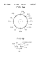
- FIG. 8A is an illustrative drawing of a rotor with the plurality of blades when viewed from a direction of a gas flow in FIG. 7;
- FIG. 8B is an enlarged view of the blade provided on a perimeter of the rotor
- FIGS. 9A and 9B are illustrative drawings showing an alternative configuration of the rotor of the second embodiment
- FIG. 10 is an illustrative drawing showing a configuration of a gas reactor according to a third embodiment of the present invention.
- FIG. 11 is an illustrative drawing showing a variation of a reaction part of the gas reactor shown in FIG. 10;
- FIG. 12 is an illustrative drawing showing a variation of a lower electrode of the gas reactor shown in FIG. 10;
- FIG. 13 is an illustrative drawing showing a variation of a catalyst layer provided on a tip of an upper electrode of the gas reactor shown in FIG. 10;
- FIG. 14 is an illustrative drawing showing a variation of the lower electrode
- FIG. 15 is an illustrative drawing showing a gas reactor according to a fourth embodiment of the present invention.
- FIG. 16 is an illustrative drawing showing a variation of a dielectric container of the gas reactor shown in FIG. 15;
- FIG. 17 is an illustrative drawing showing a variation of a floating electrode of the gas reactor shown in FIG. 15;
- FIG. 18 is an illustrative drawing showing a gas reactor according to a fifth embodiment of the present invention.
- FIG. 19 is an illustrative drawing showing a detailed configuration of blades of FIG. 18;
- FIGS. 20A through 20C are illustrative drawings showing a gas reactor according to a sixth embodiment of the present invention.
- FIG. 21 is an illustrative drawing showing a variation of the gas reactor shown in FIGS. 20A through 20C;
- FIGS. 22 is an illustrative drawing showing a gas reactor according to a seventh embodiment of the present invention.
- FIG. 23 is a chart which demonstrates a favorable effect of coupling with regard to a particular chemical reaction
- FIG. 24 is an illustrative drawing showing a variation of the seventh embodiment of the present invention.
- FIG. 25 is an illustrative drawing showing a gas reactor according to an eighth embodiment of the present invention.
- FIG. 1 is an illustrative drawing showing a configuration of a gas reactor according to the first embodiment of the present invention.
- a gas reactor 10 comprises an inner electrode 11, an outer electrode 12, a casing 13, a first catalyst 14, a second catalyst 15, a third catalyst 16, a gas-injection conduit 20 for conducting gas A, a gas-injection conduit 21 for conducting gas B, a gas-emission conduit 22 for conducting gas C, a window holder 23, a filter 24, and a power supply 30.
- the inner electrode 11 and the outer electrode 12 are made from copper, for example, and the power supply 30 supplies AC power between the inner electrode 11 and the outer electrode 12 to actuate a glow discharge.
- the casing 13 is a circular tube made from a dielectric material such as glass.
- the inner electrode 11 is a rod incorporated in an inner space of the casing 13.
- the outer electrode 12 has a circular tube shape surrounding the casing 13, and is movable in a direction shown by an arrow in FIG. 1.
- Gas A is injected through the gas-injection conduit 20, and is directed to the inner space of the casing 13, where the gas A is subjected to the glow discharge.
- the inner electrode 11 is provided with coating layers of at least two different metal catalysts.
- One of the metal catalysts is used for excitation of the gas A, and the other is used for activation of the gas A. More than one metal catalyst may be provided for the excitation of gas A, and, also, more than one metal catalyst may be provided for activation of gas A.
- two metal catalyst layers for excitation i.e., the first catalyst 14 and the second catalyst 15, are provided on the inner electrode 11, and one metal catalyst layer for activation, i.e., the third catalyst 16, is provided on the inner electrode 11 at one end of the rod.
- the first catalyst 14 and the second catalyst 15 are used for the excitation of different gases.
- gas A may be a mixture of two different gases such as methane and CO 2 .
- Rhodium may be a suitable catalyst for the excitation of methane
- nickel may be a suitable catalyst for the excitation of CO 2 .
- Gas B is injected through the gas-injection conduit 21, and meets with gas A at an intersection where the excited and activated gas A flows into gas B from the inner space defined by the casing 13.
- chemical reaction between gas A and gas B occurs, and a resulting gas C is directed through the gas-emission conduit 22.
- the outer electrode 12 is movable in the direction indicated by the arrow in FIG. 1. This movement is used for an adjustment of a length l shown in FIG. 1.
- the length l is a distance between the end of the discharge area and the intersection where gas A is mixed with gas B.
- the gas A excited in the discharge area has an inherent excitation lifetime, so that the adjustment of length l by the movement of the outer electrode 12 can control the percentage of the excited gas A which reaches the intersection to meet gas B while it is at excited levels.
- the filter 24 is provided beside the intersection where gas A meets gas B, such that the discharge area can be observed through the filter 24.
- the filter 24 is made of KBr, through which near-infrared radiation from the glow discharge is observed by an externally provided device (not shown). Based on a spectrum analysis of the near-infrared radiation, factors such as the lifetime of a particular excited gas can be measured. Such factors are fedback for adjustment of the length l.
- An example of gas reactions effected by the gas reactor 10 according to the first embodiment of the present invention includes the synthesis of methanol from methane and oxygen.
- methane is gas A of FIG. 1
- oxygen is gas B.
- Methane injected to the gas reactor 10 is excited and activated and mixed with oxygen, thereby effecting the synthesis of methanol.
- FIG. 2 is an expanded view of the gas reactor 10.
- the gas-injection conduit 20, the gas-injection conduit 21, and the gas-emission conduit 22 are formed from circular pipes commonly used in the industrial field.
- a joint part 25 is used for connecting the gas-injection conduit 20 with the casing 13 and a joint part 26 is used for connecting the gas-injection conduit 21, the casing 13, and the gas-emission conduit 22.
- FIG. 2 shows a disassembled gas reactor 10 in which the joint part 25 and the joint part 26 are disconnected from the casing 13 in directions shown by arrows.
- the joint part 25 and the joint part 26 are also commonly available in industry.
- the combination of the gas-injection conduit 20, the gas-injection conduit 21, the gas-emission conduit 22, the joint part 25, and the joint part 26 provide enough precision for the gas reactor 10, thereby avoiding gas leakage or the like.
- FIGS. 3A and 3B are cross-sectional views of the gas reactor 10 taken along a plane perpendicular to the extension of the casing 13 in the discharge area.
- the outer electrode 12 is omitted for clarity of the figures.
- the inner electrode 11 may have a circular cross section, and spacers 27 may be provided between the inner electrode 11 and the casing 13 to ensure a uniform gap (discharge area) around the circle.
- the spacers 27 may not be necessary, and the positioning of the inner electrode 11 inside the casing 13 may rely on the precision of the joint part 25 (FIG. 2) supporting the inner electrode 11.
- FIG. 3B shows a variation of the inner electrode 11.
- the inner electrode 11 may have a cross section of a regular-polygon shape, and spacers 28 may be provided on edges of the regular polygon.
- the spacers 28 may not be necessary, and the inner electrode 11 may be mainly supported inside the casing 13 by the joint part 25.
- the gas-injection conduit 21 for injecting gas B may not be necessary.
- the gas reactor 10 when used as a gas reactor for decomposing gases, the gas reactor 10 may be provided only with one gas-injection conduit and one gas-emission conduit. In the following, a serial or parallel connection of such gas reactors will be described.
- FIG. 4 is an illustrative drawing showing a serial connection of gas reactors 10A.
- FIG. 5 is an illustrative drawing showing gas reactor 10A.
- the gas reactor 10A of FIG. 5 differs from the gas reactor 10 of FIG. 1 only in that the gas-injection conduit 20, the gas-injection conduit 21, and the gas-emission conduit 22 are removed, and that a joint part 26A having only a gas-emission hole (or opening) replaces the joint part 26 having a gas-emission hole (or opening) and a gas-injection hole (or opening).
- the gas reactors 10A-1 through 10A-4 are connected in series via a connecting conduit 31, a connecting conduit 32, and another connecting conduit (not shown).
- a gas-injection conduit 20A is connected to the gas reactor 10A-1, and the gas reactor 10A-1 and the gas reactor 10A-2 are connected via the connecting conduit 31.
- the gas reactor 10A-2 and the gas reactor 10A-3 are connected via another connecting conduit, which cannot be seen from the viewpoint of the figure.
- the gas reactor 10A-3 is connected to the gas reactor 10A-4 through the connecting conduit 32, and the gas reactor 10A-4 is provided with a gas-emission conduit 22A.
- Each of the outer electrodes 12 of the gas reactors 10A-1 through 10A-4 is connected to a respective lead 34 provided from a power supply 30A. Also, a common lead 33 extends from the power supply 30A, and is connected to each of the inner electrodes 11 of the gas reactors 10A-1 through 10A-4.
- the power supply 30A provides AC power between the inner electrodes 11 and the outer electrodes 12 to generate a glow discharge.
- Gas injected from the gas-injection conduit 20A flows through the gas reactors 10A-1 through 10A-4 while gas reactions take place therein. Then, synthesized gas or decomposed gas is emitted from the gas-emission conduit 22A.
- gas flows through multiple stages of gas reactions, so that the efficiency of gas decomposition or gas synthesis can be boosted or increased.
- a gas conversion rate in the gas reaction by a single gas reactor 10A is relatively high compared to related-state-of-the-art techniques. As high as it may be, the gas conversion rate of the injected gas is no more than a 20% conversion rate, for example.
- the serial connection of the gas reactor 10A allows a much higher conversion rate by subjecting injected gas to the multiple stages of the gas reactions.
- FIG. 6 is an illustrative drawing showing a parallel connection of the gas reactors 10A.
- a plurality of the gas reactors 10A are connected in parallel between a joint conduit 35 and a joint conduit 36.
- the joint conduit 35 and the joint conduit 36 have a circular shape.
- the joint conduit 36 is connected to the joint parts 25 of the gas reactors 10A such that an inner space of the joint conduit 36 is connected to the inner spaces of the joint parts 25.
- the joint conduit 35 is connected to the joint parts 24 of the gas reactors 10A such that an inner space of the joint conduit 35 is connected to the inner spaces of the joint parts 24.
- the joint conduit 35 and the joint conduit 36 are connected to a gas-emission conduit 37 and a joint conduit 36, respectively.
- Gas injected through the gas-injection conduit 38 is supplied to the gas reactors 10A via the joint conduit 36, and flows through the gas reactors 10A where gas reaction takes place. Resulting gas is led or directed to the joint conduit 35, and emitted from the gas-emission conduit 37.
- FIG. 35 allows a large amount of gas to be subjected to gas reaction without using a gas reactor having a large size.
- the gas reactors 10A can be arranged in various configurations such as a serial or a parallel connection. Since the gas reactor 10A can be connected with other gas reactors 10A in a flexible arrangement, the combined gas reactor can be tailored to various needs for gas reaction processes.
- FIG. 7 is an illustrative drawing showing a configuration of a gas reactor according to a second embodiment of the present invention.
- the second embodiment of the present invention is an improvement over the gas cleaning equipment disclosed in U.S. Pat. No. 5,492,678.
- a gas reactor 100 comprises a casing 101, a rotor 102 housed in the casing 101, a plurality of blades 103 provided on a perimeter of the rotor 102, a catalyst layer 104 on a tip of each blade 103, an outer electrode 105 provided inside the casing 101 to surround the rotor 102, an insulator 106 placed between the outer electrode 105 and an inner wall of the casing 101, a shaft 107, a motor 108, a gas-injection opening 110, and a gas-emission opening 111.
- FIG. 8A is an illustrative drawing of the rotor 102 with the plurality of the blades 103 when viewed from a direction shown by an arrow indicating a flow of gas A in FIG. 7.
- the rotor 102 has a round shape, and is provided with the plurality of blades 103 on the perimeter thereof.
- the rotor 102 rotates in a direction indicated by a curved arrow in FIG. 8A.
- the rotor 102 is made of a conductive material, and is housed in the casing 101.
- the motor 108 uses the shaft 107 to rotate the rotor 102 inside the casing 101. Since the motor 108 is provided outside the casing 101 in this configuration, the gas reactor 100 can be easily used for a liquid-state reaction.
- the outer electrode 105 has a ring shape to surround the rotor 102, such that a gap is provided between the outer electrode 105 and each of the blades 103.
- Each blade 103 is formed from a conductive material such as Cu, and has a catalyst layer 104 on the tip thereof.
- the outer electrode 105 is made of a conductive material such as Pt.
- the gas-injection opening 110 is provided at one face of the casing 101 to provide a path through which the gas A flows into the casing 101.
- the gas-emission opening 111 is provided at an opposite face of the casing 101, so that gas A' generated by gas reaction inside the casing 101 flows out through the gas-emission opening 111.
- FIG. 8B is an enlarged view of a blade 103 provided on the perimeter of the rotor 102.
- FIG. 8B shows only an example of configurations which provide the removability of the blades 103.
- a groove 120 corresponding in shape and size to a base 121 of the blade 103 is formed along the perimeter of the rotor 102.
- the base 121 of the blade 103 is fit in groove 120 so as to be secured in the perimeter of the rotor 102.
- the blade 103 can be removed from the rotor 102 by sliding the blade 103 in a direction perpendicular to the sheet of the figure.
- the base 121 of the blade 103 increases in width towards the bottom. This shape prevents the blade 103 from being detached from the rotor 102 by centrifugal force when the rotor 102 is rotated.
- the removability of the blades 103 allows replacement of a set of the blades 103 with another set of blades 103. This makes it possible to use a different catalyst for different gas reactions. Namely, the same gas reactor 100 can be used for different gas reactions by changing a set of the blades 103 to a different set of blades 103 which is suitable for a desired gas reaction. Also, the removability of the blades 103 allows use of an electroplating process for forming the catalyst layer 104 on the tip of the blade 103. Furthermore, because of the removability of the blades 103, byproducts formed on the catalyst layer 104 and the blades 103 can be easily removed by using a chemical process. Such byproducts can also be readily used for analysis of a gas reaction because of the removability.
- Another advantage of the configuration of the second embodiment over the configuration disclosed in U.S. Pat. No. 5,492,678 is the provision of a plurality of catalyst layers. As shown in FIG. 8A, two different catalyst layers 104a and 104b are provided one each on a tip of a corresponding blade 103. The blades 103 are arranged such that the same catalyst layer is on a tip of every other blade.
- different catalysts can serve for the excitation of different gases in the same manner as in the first embodiment. Namely, when the injected gas A is a mixture of different gases, provision of different catalysts suitable for the excitation of these gases is advantageous. Also, when different catalysts are provided, one catalyst can serve for the excitation of gas and the other catalyst can serve for the activation of the gas.
- Combinations of the catalyst layer 104a and the catalyst layer 104b include a combination of Pt and Al 2 O 3 , Ru and Cu, Pt and Sn, Pt and Re, SiO 2 and Al 2 O 3 , NiO and Al 2 O 3 , etc. For example, the combination of Pt and Al 2 O 3 is useful for dehydrogenation, and the combinations of Ru and Cu, Pt and Sn, or Pt and Re are useful for oligomerization.
- FIGS. 9A and 9B are illustrative drawings showing an alternative configuration of the rotor of the second embodiment.
- FIG. 9A shows a rotor 102A with the blades 103
- FIG. 9B shows an enlarged partial view of the rotor 102A around one of the blades 103.
- the rotor 102A is provided with catalyst layers 122 on the perimeter thereof.
- the catalyst layers 122 are separated from each other by the intervening blades 103, and may be comprised of different catalysts for each interval between the blades 103. In this configuration, it is preferable that the catalyst layers 122 are removable from the blade 103.
- the gas reactor according to the second embodiment of the present invention provides for the blades to be removable from the rotor, so that a different set of the blades can be used for different gas reactions. Also, the removable blades provides for easier formation and elimination of the catalyst layers on the blades.
- FIG. 10 is an illustrative drawing showing a configuration of a gas reactor according to a third embodiment of the present invention.
- a gas reactor 220 includes a micrometer 200 and a reaction part 210.
- the micrometer 200 includes a knob 201, a scale 202, a fitting part 203, an upper electrode 204, and a catalyst layer 205.
- the reaction part 210 includes a gas-injection conduit 211, a gas-emission conduit 212, an upper hole 213, a lower hole 214, a fitting hole 215, and a lower electrode 208.
- the upper electrode 204 is movable in a direction shown by an arrow with respect to the micrometer 200.
- the relative position of the upper electrode 204 in this direction can be adjusted by turning the knob 201 of the micrometer 200.
- the scale 202 provided for the micrometer 200 gives a reading of a distance between the upper electrode 204 of the micrometer 200 and the lower electrode 208 of the reaction part 210.
- the knob 201 and the scale 202 provides a means for measuring the gap between the two electrodes.
- the fitting part 203 is provided at the lower end of the micrometer 200, and screw threads are cut in the surface of the fitting part 203.
- the fitting hole 215 of the reaction part 210 is a tapped hole, so that the fitting part 203 of the micrometer 200 can be fit into the fitting hole 215 of the reaction part 210.
- the upper electrode 204 With the fitting part 203 fit in the fitting hole 215, the upper electrode 204 is positioned inside the upper hole 213 of the reaction part 210.
- the adjustment of the position of the upper electrode 204 is effected by sliding the upper electrode 204 in the fitting hole 215 of the reaction part 210 by rotation of the knob 201.
- the gas-injection conduit 211 and the gas-emission conduit 212 is formed through the reaction part 210. Also, the reaction part 210 has the lower hole 214 to secure the lower electrode 208 inside the lower hole 214.
- the catalyst layer 205 is coated on the tip of the upper electrode 204. Voltage is applied between the upper electrode 204 and the lower electrode 208 to effect a glow discharge between the electrode.
- Gas A is injected from the gas-injection counduit 211, and flows through the gap between the upper electrode 204 and the lower electrode 208. Gas reaction is effected by a synergistic cooperation between the glow discharge and the catalyst action by the catalyst layer 205. A resulting gas A' is emitted from the gas-emission conduit 212.
- the micrometer 200 is removable from the reaction part 210 by detaching the fitting part 203 of the micrometer 200 from the fitting hole 215 of the reaction part 210, the upper electrode 204 and the catalyst layer 205 can be replaced with another electrode and catalyst layer. Therefore, various advantages such as use of an appropriate catalyst for a given gas reaction, analyzing the used electrode and catalyst layer in analysis of the gas reaction, easy formation of the catalyst layer on the electrode, etc. can be obtained.
- the gap between the upper electrode 204 and the lower hole 214 is accurately adjusted by the scale mechanism of the micrometer 200. Therefore, an appropriate adjustment of the gap between the electrode can be easily carried out.
- the third embodiment has been described with a particular example of the micrometer. However, it is obvious that any parts or equipment having a similar scale mechanism to that of the micrometer can be used in the third embodiment.
- FIG. 11 is an illustrative drawing showing a variation of the reaction part 210 of the third embodiment.
- FIG. ll shows a plan view of the reaction part 210 taken along a horizontal plane.
- the reaction part 210 includes a window 216, a filter cap 217, a filter 218, and a non-excitation-gas-injection conduit 219.
- the window 216 is arranged to provide a view of a glow-discharge area at the gap.
- the filter 218 is secured by the filter cap 217 mounted in a fixed manner to the reaction part 210.
- the filter 218 is the same type as the filter 24 used in the first embodiment. Therefore, near-infrared radiation from the glow discharge can be measured by an external device to conduct a spectrum analysis of the gas reaction.
- the non-excitation-gas-injection conduit 219 of the reaction part 210 is used for injecting non-excited gas, which is to be mixed with excited and activated gas. That is, the non-excitation-gas-injection conduit 219 plays the same role as the gas-injection conduit 21 of the first embodiment.
- FIG. 12 is an illustrative drawing showing a variation of the lower electrode 208 of the third embodiment.
- a dielectric layer 209 is coated on the tip of the lower electrode 208.
- an appropriate glow discharge can be effected.
- FIG. 13 is an illustrative drawing showing a variation of the catalyst layer 205 provided on the tip of the upper electrode 204.
- three different catalyst layers 205a through 205c are provided in a concentric manner instead of the single catalyst layer 205.
- An arrangement of the catalyst layers 205a through 205c is not limited to a concentric arrangement, and various arrangements may be used.
- the number of the catalyst layers is not limited to three, but any appropriate number of the catalyst layers may be used.
- more than one catalyst layer is provided. Therefore, different catalysts can serve for the excitation of different gases in the same manner as in the first and second embodiments. Namely, when the injected gas A is a mixture of different gases, it is advantageous to provide different catalysts suitable for the excitation of these gases. Also, when different catalysts are provided, one catalyst can serve for the excitation of gas and the other catalyst can serve for the activation of the gas.
- FIG. 14 is an illustrative drawing showing a variation of the lower electrode 208.
- the lower electrode 208 is divided into three lower electrodes 208a, 208b, and 208c, which are connected to power supplies V1 through V3, respectively.
- Resistances R1 through R3 are serially connected to the power supplies V1 through V3, respectively.
- AC power can be independently applied to each of the lower electrodes 208a through 208c.
- an AC power level and an AC-power waveform applied to each of the lower electrodes 208a through 208c can be different.
- This configuration facilitates a more complex gas reaction based on multiple glow discharges independently controlled by independent power supply systems.
- FIG. 15 is an illustrative drawing showing a gas reactor according to a fourth embodiment of the present invention.
- a gas reactor 300 of FIG. 15 includes a dielectric container 301, a float electrode 302, an outer electrode 303, a catalyst layer 304, a center electrode 305, a gas-ejection hole 306, an upper cap 307, a gas-emission conduit 308, a lower cap 309, a gas-injection conduit 310, and a power supply 311.
- the dielectric container 301 is made of a dielectric material such as glass, and has a tube shape with a circular horizontal cross section.
- the upper cap 307 is mounted in a fixed manner.
- the lower cap 309 is mounted in a fixed manner at the bottom of the dielectric container 301.
- the gas reactor 300 is positioned vertically such that the bottom of the dielectric container 301 is directed toward the ground.
- the center electrode 305 is secured between the upper cap 307 and the lower cap 309, and has screw threads cut on the surface thereof.
- the center electrode 305 is a hollow pipe serving as a conduit for gas B, which is injected from the bottom of the center electrode 305 and ejected from the gas-ejection hole 306.
- the float electrode 302 has a tapped hole 302a at a center thereof, and the center electrode 305 extends through the tapped hole 302a.
- the float electrode 302 moves upward or downward in a direction shown by an arrow A-B along the center electrode 305 by rotating around the center electrode 305. Since the gas reactor 300 is positioned vertically, the float electrode 302 is constantly subjected to gravitational forces applied in direction A.
- the lower cap 309 has the gas-injection conduit 310 through which gas A is injected.
- Gas A flows upward inside the dielectric container 301, and is emitted from the gas-emission conduit 308 provided at the upper cap 307. Since gas A flows in direction B, the float electrode 302 is subjected to an upwardly directed force of the gas flow.
- the outer electrode 303 made of a conductive material such as Cu is provided to surround the dielectric container 301.
- the power supply 311 applies AC power between the outer electrode 303 and the center electrode 305.
- the float electrode 302 is electrically connected to the center electrode 305, and is made of an electrically conductive material. Also, the float electrode 302 has the catalyst layer 304 formed on the side surface thereof. Thus, when AC power is applied between the center electrode 305 and the outer electrode 303, a glow discharge is generated between the catalyst layer 304 and the outer electrode 303 via the dielectric container 301.
- the glow discharge and the catalyst action together effect a gas reaction of the injected gas A.
- gas B injected into the center electrode 305 is ejected from the gas-ejection hole 306 to be mixed with the excited and activated gas A.
- gas C is created to be emitted from the gas-emission conduit 308.
- the gas-ejection hole 306 does not have to be necessarily provided in the gas reactor 300. If the gas-ejection hole 306 is not provided, the gas reactor 300 serves as a gas reactor only for gas A injected through the gas injection conduit 310.
- a size of the gap between the float electrode 302 (catalyst layer 304) and the dielectric container 301 varies depending on a position of the dielectric container 301. Namely, the gap size is D1 when the float electrode 302 is positioned at position P1, and is D2 when the float electrode 302 is positioned at position P2. Finally, it becomes D3 when the float electrode 302 is positioned at position P3. In this manner, the gap becomes larger toward the top of the dielectric container 301. That is, the gap becomes larger as the gas quantity per unit time is increased.
- the AC power applied by the power supply 311 is assumed to be constant.
- the magnitude of the electric field is reciprocal to the gap size, so that this magnitude becomes weaker as the gas quantity per unit time is increased. That is, this configuration allows an adjustment of the magnitude of the electric field despite the constant AC power applied by the power supply 311.
- a suitable magnitude of the electric field for the gas reaction of C, CH, CH 2 , CH 3 , or CH 4 becomes weaker in this order (i.e., the weakest for gas reactions of CH 4 ).
- FIG. 16 is an illustrative drawing showing a variation of the dielectric container 301 of the fourth embodiment.
- a configuration of FIG. 16 is the same as the configuration of FIG. 15 except for the shape of the dielectric container 301.
- FIG. 16 only necessary elements for explaining the differences between FIG. 15 and FIG. 16 are shown in FIG. 16, and the other elements that are same as those of FIG. 15 are omitted.
- a dielectric container 301a replaces the dielectric container 301 of FIG. 15.
- the dielectric container 301a differs from the dielectric container 301 only in the shape thereof.
- the dielectric container 301 had a uniform thickness from the top to the bottom thereof.
- the dielectric container 301a of FIG. 16 has a thickness which is thicker toward the bottom thereof.
- the magnitude of the electric field at a given vertical position is determined by the thickness of the dielectric container 301a as well as the gap size D between the inner wall of the dielectric container 301a and the float electrode 302.
- the electric field can be provided with a desired magnitude distribution in the vertical direction by adjusting the thickness of the dielectric material.
- the glow discharge generated by such electric-field distributions may be useful for facilitating the gas reactions.
- the float electrode 302 may have a regular cylinder shape with a constant diameter from the bottom to the top. Even in this case, use of the dielectric container 301a may provide uniform distribution of the magnitude of the electric field between the float electrode 302 and the inner wall of the dielectric container 301a if the thickness of the dielectric container 301a is so adjusted. In this manner, there are many variations in the shape of the float electrode 302 and the shape of the dielectric container 301. The particular examples described here are not intended to limit the scope of the present invention in this regard.
- FIG. 17 is an illustrative drawing showing a variation of the float electrode of the fourth embodiment.
- a float electrode 302b has a stair-stepped shape as shown in FIG. 17.
- a catalyst layer 304a and a catalyst layer 304b are each provided for each of the stair steps.
- catalyst layer 304a may be used for the excitation of gas A
- catalyst layer 304b may be used for the activation of excited gas A. Because of the stair-stepped shape of the float electrode 302b, the electric-field magnitude created at the position of the catalyst layer 304a is different from that created at the catalyst layer 304b. Thus, different magnitudes of the electric field respectively suitable for the excitation and the activation of gas A can be used in this configuration. In effect, the absence of glow discharge is desirable for the catalyst layer 304b for the activation of gas A.
- the number of catalyst layers is not limited to two as shown in this example, and, also, the shape of the float electrode 302 is not limited to the stair-stepped shape.
- more than one catalyst layer may be provided on the side surface of the float electrode 302 of FIG. 15 without any change in the shape of the float electrode 302.
- only one catalyst layer may be provided on the side surface of a float electrode having a regular cylindrical shape.
- more than one catalyst layer may be provided on the side surface of such a cylindrical float electrode.
- FIG. 18 is an illustrative drawing showing a gas reactor according to a fifth embodiment of the present invention.
- a gas reactor 400 of FIG. 18 includes a casing 401, an outer electrode 402, a rotational shaft 403, blades 404, sub-blades 404a, a catalyst layer 405a, a catalyst layer 405b, a reaction chamber 409, a gas-injection conduit 410, a gas-emission conduit 411, and a non-excitation-gas injection conduit 412.
- the casing 401 is made of a dielectric material such as glass, and contains the reaction chamber 409 where gas reaction takes place.
- the reaction chamber 409 has a substantially round shape.
- the casing 401 has the gas-injection conduit 410 for leading or directing injected gas A to the reaction chamber 409, and has a gas-emission conduit 411 for leading synthesized gas C from the reaction chamber 409 to the outside of the casing 401.
- the casing 401 has a non-excitation-gas-injection conduit 412 for leading gas B to the reaction chamber 409.
- the outer electrode 402 is attached in a fixed manner to the outside wall of the casing 401 around the reaction chamber 409.
- the rotational shaft 403 made of a conductive material is provided at a general center thereof.
- a plurality of blades 404 made of a conductive material such as Cu are attached to the rotational shaft 403, a plurality of blades 404 made of a conductive material such as Cu are attached.
- the rotational shaft 403 is rotated in a direction shown by a curved arrow by a driving motor (not shown). AC power is also applied between the rotational shaft 403 and the outer electrode 402 to effect a glow discharge between tip edges of blades 404 and the outer electrode 402 via dielectric material of the casing 401.
- FIG. 19 is an illustrative drawing showing a detailed configuration of the blades 404.
- FIG. 19 shows a view of the blades 404 taken from a direction perpendicular to the rotational shaft 403.
- the catalyst layer 405a is provided at the tip edge of the blade 404
- the catalyst layer 405b is provided on a surface of the blade 404 from which the sub-blade 404a extends.
- the catalyst layer 405a is used for the excitation of the gas A
- the catalyst layer 405b is used for the activation of the excited gas A.
- the glow discharge generated at gaps between the blades 404 and the inside wall of the reaction chamber 409 brings about gas reaction of gas A synergistically with the catalytic action.
- Gas A excited by the glow discharge and the catalytic action based on the catalyst layer 405a is activated by catalytic action based on the catalyst layer 405b.
- the exited and activated gas A is mixed with gas B injected into the reaction chamber 409 via the non-excitation-gas-injection conduit 412.
- Gas C resulting from the gas reaction of gas A and gas B is then emitted through the gas-emission conduit 411.
- the thickness of the casing 401 varies around the reaction chamber 409 where the outer electrode 402 is attached. This variation in the thickness of the casing 401 is provided to effect a glow discharge having different magnitudes at different points. Depending on the type of gas reaction, such glow discharge may be useful for facilitating the gas reaction. Alternately, the thickness of the casing 401 may be uniform around the reaction chamber 409 to generate a constant glow discharge.
- the gas reactor 400 of the fifth embodiment can effectively bring about a gas reaction between an excited and activated gas and a non-excited gas.
- the configuration of the gas reactor 400 according to the fifth embodiment of the present invention may be such that the blades 404 are removable from the rotational shaft 403 in the same manner as in the second embodiment. In this case, different catalysts can be used for different gas reactions.
- FIGS. 20A through 20C are illustrative drawings showing a gas reactor according to a sixth embodiment of the present invention.
- a gas reactor 500 of the sixth embodiment includes a dielectric container 501, a float electrode 502, an outer electrode 503, a catalyst layer 504a, a catalyst layer 504b, a center electrode 505, a resistor R, and a power supply V.
- the dielectric container 501 is made of a dielectric material such as glass, and has a tube-like shape forming a conduit for leading or directing gas A. Surrounding the dielectric container 501, the outer electrode 503 is provided on the outer surface of the dielectric container 501. The center electrode 505 is positioned to extend along a general center of the dielectric container 501. The power supply V and the resistor R are serially connected between the outer electrode 503 and the center electrode 505 to apply AC power between these two electrodes.
- the float electrode 502 has a hole formed through a general center thereof, and the center electrode 505 is inserted through this hole.
- the float electrode 502 is movable in a direction shown by an arrow A-B by sliding along the center electrode 505.
- the gas reactor 500 is vertically positioned such that gravitational force is applied to the float electrode 502 in direction A.
- the float electrode 502 is positioned at the bottom of the dielectric container 501 when no gas flows through the dielectric container 501.
- gas A flows through the dielectric container 501 in direction B
- an upwardly directed force by the gas flow is applied to the float electrode 502 to keep the float electrode 502 in a floating position as shown in FIG. 20B or FIG. 20C.
- the float electrode 502 has a lower portion keeping a distance D1 from the inner wall of the dielectric container 501, and has an upper portion tapering toward the top thereof.
- the upper portion of the float electrode 502 keeps a varying distance from the inner wall of the dielectric container 501, and this varying distance increases from D1 at a joint with the lower portion and to D2 at the top of the float electrode 502.
- the catalyst layer 504a is provided on the surface of the upper portion of the float electrode 502.
- the catalyst layer 504b is provided on the surface of the lower portion of the float electrode 502.
- the catalyst layer 504a and the catalyst layer 504b may be formed from different catalysts.
- the float electrode 502 When no gas is injected into the dielectric container 501, the float electrode 502 is positioned at the bottom of the dielectric container 501 as shown in FIG. 20A. In this case, the power supply V is controlled to apply no AC power between the center electrode 505 and the outer electrode 503.
- the float electrode 502 When gas A is injected into the dielectric container 501 from the bottom thereof, the float electrode 502 is floated by the gas flow as shown in FIG. 20B.
- the power supply V applies AC power between the center electrode 505 and the outer electrode 503. Since only the upper portion of the float electrode 502 is positioned within a discharge area 506 surrounded by the outer electrode 503, a glow discharge is generated only between the catalyst layer 504a and the inner wall of the dielectric container 501. In this case, the generated glow discharge is relatively weak because the distance between the catalyst layer 504a and the inner wall of the dielectric container 501 is relatively large.
- the float electrode 502 When a larger amount of gas A per unit time is injected into the dielectric container 501, the float electrode 502 is floated further up by the gas flow as shown in FIG. 20C. Since the lower portion as well as the upper portion of the float electrode 502 are within the discharge area 506, a glow discharge is generated between the catalyst layer 504a and the inner wall of the dielectric container 501 and between the catalyst layer 504b and the inner wall of the dielectric container 501. As previously noted, the distance between a catalyst layer and the inner wall of the dielectric container 501 is larger for the lower portion of the float electrode 502 than for the upper portion of the float electrode 502. Thus, the glow discharge between the catalyst layer 504a and the inner wall of the dielectric container 501 is relatively weak, and the glow discharge between the catalyst layer 504b and the inner wall of the dielectric container 501 is relatively strong.
- FIG. 21 is an illustrative drawing showing a variation of the gas reactor 500 of FIGS. 20A through 20C.
- the same elements as those of FIGS. 20A through 20C are referred to by the same numerals, and a description thereof will be omitted.
- the gas reactor 500A of FIG. 21 includes a non-excitation-gas conduit 510 in addition to all the elements provided in the gas reactor 500.
- Gas B is injected through the non-excitation-gas conduit 510 into the dielectric container 501 to be mixed with the excited and activated gas A.
- Mixing of gas B with gas A takes place downstream with regard to the gas flow compared to the discharge area 506. That is, the mixture occurs at a point higher than the top edge of the outer electrode 503.
- the glow discharge and the catalytic action do not have any influence on gas B itself, and gas B remains non-excited when mixed with gas A.
- gas reaction can be effected between a non-excited gas and an excited and activated gas in the same manner as in the first embodiment.
- FIGS. 22 is an illustrative drawing showing a gas reactor according to a seventh embodiment of the present invention.
- a gas reactor 600 of FIG. 22 includes a Y-shaped casing 601, outer electrodes 602a and 602b, and inner electrodes 603a and 603b.
- the Y-shaped casing 601 is made of a dielectric material such as glass, and may have a circular tube shape to allow gas to flow inside.
- the Y-shaped casing 601 includes a gas-injection conduit 601a, a gas-injection conduit 601b, and a gas-ejection conduit 601c, which are connected with each other at one end to form a Y shape.
- the outer electrode 602a is provided to surround the gas-injection conduit 601a, and the outer electrode 602b envelops the gas-injection conduit 601b.
- the outer electrodes 602a and 602b are made of copper or the like.
- the inner electrodes 603a and 603b are placed inside the gas-injection conduits 601a and 601b, respectively, at a general center of the circular cross section.
- the inner electrodes 603a and 603b may be made of copper or the like with a coated catalyst layer, or may be made of a catalyst.
- AC power is applied between the outer electrode 602a and the inner electrode 603a as well as between the outer electrode 602b and the inner electrode 603b so as to generate glow discharge inside the Y-shaped casing 601.
- the glow discharge excites the gas A and the gas B, and the catalyst helps to activate the excited gas A and gas B.
- the excited and activated gas A and gas B are mixed to effect chemical reaction, thereby producing gas C which is ejected from the gas-ejection conduit 601c.
- the outer electrodes 602a and 602b are movable along the extension of the gas-injection conduits 601a and 601b, respectively.
- the gas A and the gas B can be mixed while plasma action created by the glow discharge is taking place. That is, the plasma action is present where the excited and activated gas A meets with the excited and activated gas B. This condition may further facilitate the chemical reaction.
- this condition is referred to as "coupling".
- whether to establish the coupling condition is dependent on the position of the outer electrodes 602a and 602b along the extension of the gas-injection conduits 601a and 601b, respectively.
- the outer electrodes 602a and 602b may be provided to cover the full extent of the gas-injection conduits 601a and 601b, respectively, and the inner electrodes 603a and 603b may be inserted more or inserted less into the gas injection conduits 601a and 601b, respectively, to adjust the extent of the area where glow discharge is generated.
- FIG. 23 is a chart which demonstrates a favorable effect of coupling with regard to a particular chemical reaction.
- FIG. 23 shows a chemical reaction between CO 2 and H 2 effected by the gas reactor 600 of FIG. 22 when CO 2 and H 2 are injected to the gas-injection conduits 601a and 602a, respectively.
- iron is used as a material for the inner electrodes 603a and 603b.
- AC power applied between the outer electrode 602a and the inner electrode 603a as well as the outer electrode 602b and the inner electrode 603b has a voltage of 9.3 kV and a frequency of 8.2 kHz.
- the Y-shaped casing 601 has a diameter of 10 mm at portions having a straight-tube shape.
- the abscissa shows passage of time, and the ordinate shows density of each gas component measured in mols.
- glow discharge is started only with respect to CO 2 .
- the density of CO 2 decreases as shown in the figure, and, at the same time, CO and H 2 O, obtained as products of the reaction, increase in density.
- the densities of CO 2 , CO, and H 2 O stabilizes at constant levels.
- glow discharge is also started with respect to H 2 , and the coupling condition is installed.
- the glow discharge is stopped, and the outer electrodes 602a and 602b are brought back to their original position. Density of each gas returns to its original level.
- glow discharge is generated with respect to both CO 2 and H 2 , but coupling is not put in place. Density of CO 2 decreases while densities of CO and H 2 O increase. The decrease in CO 2 and the increases in CO and H 2 O are larger than when only CO 2 is subjected to plasma action, but fails to reach levels which are attained by the coupling.
- Table 1 shows another chemical reaction, i.e., a chemical reaction between H 2 and CO.
- the column labeled as CO(%) represents a conversion rate at which injected CO is converted to something else. That is, the conversion rate is the same as the decreased amount of CO represented as a percentage to the total injected amount of CO.
- Columns labeled as H 2 O(%), CO 2 (%), and CH 4 (%) represent selectivities of H 2 O, CO 2 , and CH 4 , respectively.
- Selectivity of H 2 O for example, represents a percentage which H 2 O accounts for in the total amount of output products.
- asterisk “*” means that a gas marked by this symbol is subjected to plasma action.
- the symbol "+” represents simple mixing of H 2 and CO, whereas the symbol "/" represents coupling of H 2 and CO.
- coupling achieves the highest conversion rate of CO and the highest selectivity of H 2 O. That is, when coupling is employed, CO is converted to other products at a rate higher than other cases, and the reaction (1) producing H 2 O is favored over the reaction (2) which generates CO 2 . On the other hand, a non-coupling mixture of plasma CO and plasma H 2 favors the reaction (2) over the reaction (1), thereby producing more CO 2 and less H 2 O than the case of coupling.
- the gas reactor of the seventh embodiment allows both the gas A and the gas B to be subjected to plasma action effected by glow discharge, and mixes the gas A and the gas B to produce gas C. If preferred, the gas reactor of the seventh embodiment can mix the gas A and the gas B while they are involved in the plasma action. It is apparent that the gas reactor of the seventh embodiment can generate glow discharge with respect to only one of the gas A and the gas B. A decision as to which one of the above conditions is to be used may be made in view of an intended chemical reaction.
- FIG. 24 is an illustrative drawing showing a variation of the seventh embodiment of the present invention.
- a gas reactor 610 of FIG. 24 includes a T-shaped casing 611, an outer electrode 612, and an inner electrode 613.
- the T-shaped casing 611 is made of a dielectric material such as glass, and may have a circular tube shape to allow gas to flow inside.
- the T-shaped casing 611 includes a gas-injection conduit 611a, a gas-injection conduit 611b, and a gas-ejection conduit 611c, which are connected with each other at one end to form a T shape.
- the outer electrode 612 is provided to surround the T-shaped casing 611 around an intersection where the gas-injection conduit 611a, the gas-injection conduit 611b, and the gas-ejection conduit 611c meet.
- the outer electrode 612 is made of copper or the like.
- the inner electrode 613 is placed inside the T-shaped casing 611 at a general center of the circular cross-section.
- the inner electrode 613 may be made of copper or the like with a coated catalyst layer, or may be made of a catalyst.
- the glow discharge excites the gas A and the gas B, and the catalyst helps to activate the excited gas A and gas B.
- the excited and activated gas A and gas B are mixed to effect chemical reaction, thereby producing gas C which is ejected from the gas-ejection conduit 611c.
- the gas reactor of a variation of the seventh embodiment allows both the gas A and the gas B to be subjected to plasma action effected by glow discharge, and mixes the gas A and the gas B while they are involved in the plasma action. Because of the plasma action and coupling of both of the gases A and B, a higher conversion rate and a higher selectivity can be achieved with respect to an intended chemical reaction.
- FIG. 25 is an illustrative drawing showing a gas reactor according to an eighth embodiment of the present invention.
- a gas reactor 700 of FIG. 25 includes a casing 701, an outer electrode 702, and an inner electrode 703.
- the casing 701 is made of a dielectric material such as glass, and has a circular tube shape.
- the outer electrode 702 is attached to and wrapped around the casing 701.
- the outer electrode 702 is made of copper or the like.
- the inner electrode 703 may be made of copper or the like with a catalyst layer coated thereon, or may be made of a catalyst.
- the inner electrode 703 has a hollow structure such as that of a circular tube, and one or more holes such as holes 703a through 703c are provided to connect between the inside and outside of the inner electrode 703.
- Gas A is injected into the casing 701, and gas B is injected into the inner electrode 703.
- the gas B comes out of the inner electrode 703 through the holes 703a through 703c.
- Some of the holes 703a through 703c may be provided within the discharge area where glow discharge is effected between the outer electrode 702 and the inner electrode 703. Because of this, both of the gases A and B are subjected to the glow discharge, and are activated by catalyst action with the catalyst. The excited and activated gases A and B are mixed in the discharge area where plasma action is taking place, so that the condition of coupling as previously described is established in the configuration of FIG. 25.
- the number and positions of the holes 703a through 703c may be decided in advance with regard to a particular chemical reaction. Such a decision may be made based on conversion rates and selectivities measured in a test which is conducted under various conditions with regard to numbers and positions of the holes. Depending on circumstances, there may be a case in which only one hole is provided outside the discharge area at such a position as that of the hole 703c.
- the configuration of the eighth embodiment relates to the gas reactor 300 of the fourth embodiment shown in FIG. 15.
- the gas-ejection hole 306 is provided outside the discharge area downstream with regard to the flow of the gas A.
- the gas B ejected through the gas-ejection hole 306 is neither excited nor activated when mixed with the excited and activated gas A.
- the configuration of the gas reactor 300 shown in FIG. 15 may be changed such that the gas-ejection hole 306 is provided in the discharge area. Further, one or more holes similar to the gas-ejection hole 306 may be provided in addition to the gas-ejection hole 306. In such a new configuration, the gas reactor 300 can establish the coupling of the gas A and the gas B to achieve a higher conversion rate and a selectivity for an intended chemical reaction.
Abstract
Description
              TABLE 1
______________________________________
CONDITION
         V(kV)   I(mA)   CO(%) H.sub.2 O(%)
                                     CO.sub.2 (%)
                                           CH.sub.4 (%)
______________________________________
H.sub.2 * + CO
         1.96    12.1     5.6  9.1   40.9  50.0
  H.sub.2 + CO* 1.96 14.7 16.5 0.0 50.4 49.6
  H.sub.2 * + CO* 1.96 24.5 16.6 7.2 43.0 49.8
  H.sub.2 */CO* 1.96 24.1 18.8 26.6  23.4 50.0
______________________________________
CO+H.sub.2 =CH.sub.4 +H.sub.2 O (1)
2CO+2H.sub.2 =CO.sub.2 +CH.sub.4 (2)
Claims (32)
Priority Applications (2)
| Application Number | Priority Date | Filing Date | Title |
|---|---|---|---|
| US08/888,834 US6027617A (en) | 1996-08-14 | 1997-07-07 | Gas reactor for plasma discharge and catalytic action |
| JP21876397A JP3943664B2 (en) | 1996-08-14 | 1997-08-13 | Gas reactor |
Applications Claiming Priority (2)
| Application Number | Priority Date | Filing Date | Title |
|---|---|---|---|
| US70238696A | 1996-08-14 | 1996-08-14 | |
| US08/888,834 US6027617A (en) | 1996-08-14 | 1997-07-07 | Gas reactor for plasma discharge and catalytic action |
Related Parent Applications (1)
| Application Number | Title | Priority Date | Filing Date |
|---|---|---|---|
| US70238696A Continuation-In-Part | 1996-08-14 | 1996-08-14 |
Publications (1)
| Publication Number | Publication Date |
|---|---|
| US6027617A true US6027617A (en) | 2000-02-22 |
Family
ID=27106956
Family Applications (1)
| Application Number | Title | Priority Date | Filing Date |
|---|---|---|---|
| US08/888,834 Expired - Lifetime US6027617A (en) | 1996-08-14 | 1997-07-07 | Gas reactor for plasma discharge and catalytic action |
Country Status (2)
| Country | Link |
|---|---|
| US (1) | US6027617A (en) |
| JP (1) | JP3943664B2 (en) |
Cited By (12)
| Publication number | Priority date | Publication date | Assignee | Title |
|---|---|---|---|---|
| US6284157B1 (en) * | 1997-12-27 | 2001-09-04 | Abb Research Ltd. | Process for producing an H2-CO gas mixture |
| US20030059341A1 (en) * | 2000-03-09 | 2003-03-27 | Genomic S.A. | Automated device for biological analysis |
| WO2003080504A1 (en) * | 2002-03-27 | 2003-10-02 | Jisouken Co., Ltd. | Device for forming hydrogen using hydrocarbon or oxygen-containing compound as material and discharge electrode for use therein |
| US20030233019A1 (en) * | 2002-03-19 | 2003-12-18 | Sherwood Steven P. | Gas to liquid conversion process |
| US6767434B1 (en) | 1999-09-27 | 2004-07-27 | Ngk Insulators, Ltd. | Method of treating substance and apparatus for carrying out the same |
| US20050288541A1 (en) * | 2002-03-19 | 2005-12-29 | Sherwood Steven P | Gas to liquid conversion process |
| US20060280678A1 (en) * | 2004-12-07 | 2006-12-14 | Lee Hwa U | Apparatus and method for preparing synthesis gas by using barrier discharge reaction |
| US20070059235A1 (en) * | 2005-09-15 | 2007-03-15 | Voecks Gerald E | Rapid activation catalyst systemin a non-thermal plasma catalytic reactor |
| US20090159432A1 (en) * | 2006-08-28 | 2009-06-25 | Mitsubishi Heavy Industries, Ltd. | Thin-film deposition apparatus using discharge electrode and solar cell fabrication method |
| CN101129100B (en) * | 2005-02-04 | 2011-02-02 | 佛兰芒技术研究所有限公司 | Atmospheric-pressure plasma jet |
| US20110139751A1 (en) * | 2008-05-30 | 2011-06-16 | Colorado State Univeristy Research Foundation | Plasma-based chemical source device and method of use thereof |
| WO2012112065A1 (en) * | 2011-02-18 | 2012-08-23 | "Крено Инвест Са" | Method and device for generating synthesis gas |
Families Citing this family (4)
| Publication number | Priority date | Publication date | Assignee | Title |
|---|---|---|---|---|
| JP4555947B2 (en) * | 2000-07-14 | 2010-10-06 | 富士通株式会社 | Chemical reaction apparatus and chemical reaction method |
| KR100479990B1 (en) * | 2002-04-08 | 2005-03-30 | 이동훈 | Plasma reactor |
| JP4727419B2 (en) * | 2003-05-08 | 2011-07-20 | 株式会社事業創造研究所 | Hydrogen generator using hydrocarbon, organic oxygen-containing compound as raw material, and discharge electrode used therefor |
| JP2006248847A (en) * | 2005-03-10 | 2006-09-21 | Nissan Motor Co Ltd | Fuel reformer and fuel reforming apparatus |
Citations (3)
| Publication number | Priority date | Publication date | Assignee | Title |
|---|---|---|---|---|
| DE4220865A1 (en) * | 1991-08-15 | 1993-02-18 | Asea Brown Boveri | Hydrogenation of carbon di:oxide esp. to methane or methanol in plasma - which can operate at low temp. and low pressure, using hydrogen@ or water vapour |
| US5474747A (en) * | 1992-11-27 | 1995-12-12 | Fujitsu Ltd. | Gas purifier using plasma and catalyst |
| US5492678A (en) * | 1993-07-23 | 1996-02-20 | Hokushin Industries, Inc. | Gas-cleaning equipment and its use |
-
1997
- 1997-07-07 US US08/888,834 patent/US6027617A/en not_active Expired - Lifetime
- 1997-08-13 JP JP21876397A patent/JP3943664B2/en not_active Expired - Fee Related
Patent Citations (3)
| Publication number | Priority date | Publication date | Assignee | Title |
|---|---|---|---|---|
| DE4220865A1 (en) * | 1991-08-15 | 1993-02-18 | Asea Brown Boveri | Hydrogenation of carbon di:oxide esp. to methane or methanol in plasma - which can operate at low temp. and low pressure, using hydrogen@ or water vapour |
| US5474747A (en) * | 1992-11-27 | 1995-12-12 | Fujitsu Ltd. | Gas purifier using plasma and catalyst |
| US5492678A (en) * | 1993-07-23 | 1996-02-20 | Hokushin Industries, Inc. | Gas-cleaning equipment and its use |
Cited By (15)
| Publication number | Priority date | Publication date | Assignee | Title |
|---|---|---|---|---|
| US6284157B1 (en) * | 1997-12-27 | 2001-09-04 | Abb Research Ltd. | Process for producing an H2-CO gas mixture |
| US6767434B1 (en) | 1999-09-27 | 2004-07-27 | Ngk Insulators, Ltd. | Method of treating substance and apparatus for carrying out the same |
| US7285244B2 (en) * | 2000-03-09 | 2007-10-23 | Genomic S.A. | Automated device for biological analysis |
| US20030059341A1 (en) * | 2000-03-09 | 2003-03-27 | Genomic S.A. | Automated device for biological analysis |
| US20030233019A1 (en) * | 2002-03-19 | 2003-12-18 | Sherwood Steven P. | Gas to liquid conversion process |
| US20050288541A1 (en) * | 2002-03-19 | 2005-12-29 | Sherwood Steven P | Gas to liquid conversion process |
| WO2003080504A1 (en) * | 2002-03-27 | 2003-10-02 | Jisouken Co., Ltd. | Device for forming hydrogen using hydrocarbon or oxygen-containing compound as material and discharge electrode for use therein |
| US20060280678A1 (en) * | 2004-12-07 | 2006-12-14 | Lee Hwa U | Apparatus and method for preparing synthesis gas by using barrier discharge reaction |
| CN101129100B (en) * | 2005-02-04 | 2011-02-02 | 佛兰芒技术研究所有限公司 | Atmospheric-pressure plasma jet |
| US20070059235A1 (en) * | 2005-09-15 | 2007-03-15 | Voecks Gerald E | Rapid activation catalyst systemin a non-thermal plasma catalytic reactor |
| US7622088B2 (en) | 2005-09-15 | 2009-11-24 | Gm Global Technology Operations, Inc. | Rapid activation catalyst system in a non-thermal plasma catalytic reactor |
| US20090159432A1 (en) * | 2006-08-28 | 2009-06-25 | Mitsubishi Heavy Industries, Ltd. | Thin-film deposition apparatus using discharge electrode and solar cell fabrication method |
| US20110139751A1 (en) * | 2008-05-30 | 2011-06-16 | Colorado State Univeristy Research Foundation | Plasma-based chemical source device and method of use thereof |
| US9288886B2 (en) * | 2008-05-30 | 2016-03-15 | Colorado State University Research Foundation | Plasma-based chemical source device and method of use thereof |
| WO2012112065A1 (en) * | 2011-02-18 | 2012-08-23 | "Крено Инвест Са" | Method and device for generating synthesis gas |
Also Published As
| Publication number | Publication date |
|---|---|
| JP3943664B2 (en) | 2007-07-11 |
| JPH11552A (en) | 1999-01-06 |
Similar Documents
| Publication | Publication Date | Title |
|---|---|---|
| US6027617A (en) | Gas reactor for plasma discharge and catalytic action | |
| JP5252931B2 (en) | Ceramic plasma reactor and plasma reactor | |
| KR20000063014A (en) | Fuel synthesis | |
| Wen et al. | Decomposition of CO2 using pulsed corona discharges combined with catalyst | |
| EP0399833B1 (en) | Novel solid multi-component membranes, electrochemical reactor and use of membranes and reactor for oxidation reactions | |
| Brock et al. | Plasma decomposition of CO2in the presence of metal catalysts | |
| Liu et al. | Nonoxidative methane conversion to acetylene over zeolite in a low temperature plasma | |
| CA2204353C (en) | Ozone generator | |
| JP2006261040A (en) | Plasma reactor | |
| US20060124445A1 (en) | Electrical heating reactor for gas phase reforming | |
| ES2119808T3 (en) | PROCEDURE FOR THE CONVERSION OF METHANE IN SYNTHESIS GAS. | |
| DE19581551B4 (en) | gas reactor | |
| EP3055051B1 (en) | Process for dehydroaromatization of alkanes with in-situ hydrogen removal | |
| Hofstad et al. | Partial oxidation of methane over platinum metal gauze | |
| Gallon et al. | Dry reforming of methane using non-thermal plasma-catalysis | |
| WO2002092499A1 (en) | Method and apparatus for liquid phase reforming of hydrocarbon or oxygen-containing compound | |
| JPWO2005001249A1 (en) | Plasma generating electrode, plasma reactor, and exhaust gas purification device | |
| CN1181717A (en) | Process and device for the conversion of a greenhouse gas | |
| CA2447922C (en) | Method and apparatus for steam reforming of chain hydrocarbon | |
| EP1976345A1 (en) | Electrode device for plasma discharge | |
| JP2005519729A (en) | Chemical processing by non-thermal discharge plasma | |
| US5068485A (en) | Activation of methane by transition metal-substituted aluminophosphate molecular sieves | |
| US6113747A (en) | Method of and apparatus for manufacturing methanol | |
| Baussart et al. | A macroscopic study of Cu/Zn/Al catalyst for carbon dioxide hydrogenation | |
| RU2144844C1 (en) | Catalyst (its versions) and process of synthesis gas production |
Legal Events
| Date | Code | Title | Description |
|---|---|---|---|
| AS | Assignment |
Owner name: UNIVERSITY OF CONNECTICUT, THE, CONNECTICUT Free format text: ASSIGNMENT OF ASSIGNORS INTEREST;ASSIGNORS:HAYASHI, YUJI;SUIB, STEVEN L.;MATSUMOTO, HIROSHIGE;AND OTHERS;REEL/FRAME:009217/0791;SIGNING DATES FROM 19970902 TO 19971016 Owner name: HOKUSHIN CORPORATION, JAPAN Free format text: ASSIGNMENT OF ASSIGNORS INTEREST;ASSIGNORS:HAYASHI, YUJI;SUIB, STEVEN L.;MATSUMOTO, HIROSHIGE;AND OTHERS;REEL/FRAME:009217/0791;SIGNING DATES FROM 19970902 TO 19971016 Owner name: FUJITSU LIMITED, JAPAN Free format text: ASSIGNMENT OF ASSIGNORS INTEREST;ASSIGNORS:HAYASHI, YUJI;SUIB, STEVEN L.;MATSUMOTO, HIROSHIGE;AND OTHERS;REEL/FRAME:009217/0791;SIGNING DATES FROM 19970902 TO 19971016 Owner name: HONDA GIKEN KOGYO KABUSHIKI KAISHA, JAPAN Free format text: ASSIGNMENT OF ASSIGNORS INTEREST;ASSIGNORS:HAYASHI, YUJI;SUIB, STEVEN L.;MATSUMOTO, HIROSHIGE;AND OTHERS;REEL/FRAME:009217/0791;SIGNING DATES FROM 19970902 TO 19971016 |
|
| STCF | Information on status: patent grant |
Free format text: PATENTED CASE |
|
| FEPP | Fee payment procedure |
Free format text: PAYOR NUMBER ASSIGNED (ORIGINAL EVENT CODE: ASPN); ENTITY STATUS OF PATENT OWNER: LARGE ENTITY |
|
| CC | Certificate of correction | ||
| FPAY | Fee payment |
Year of fee payment: 4 |
|
| FPAY | Fee payment |
Year of fee payment: 8 |
|
| AS | Assignment |
Owner name: SYNZTEC CO., LTD., JAPAN Free format text: MERGER;ASSIGNOR:HOKUSHIN CORPORATION;REEL/FRAME:020353/0799 Effective date: 20070402 |
|
| FPAY | Fee payment |
Year of fee payment: 12 |